ADMET Gauge Buster 2 User manual

-2-
Gauge Buster 2 Operations Manual ADMET, Inc.
Table of Contents
FOREWARD ....................................................................................................3
1.0 INTRODUCTION........................................................................................4
1.1 Gauge Buster 2 Features ............................................................................................................................4
1.2 Gauge Buster 2 Options..............................................................................................................................5
1.3 Gauge Buster 2 Reporting Capabilities .......................................................................................................5
1.3.1 GageSafeTM Data Exchange Program....................................................................................................5
1.3.2 USB Flash (Thumb) Drive ........................................................................................................................5
1.3.3 HP compatible USB Printer ......................................................................................................................5
2.0 THE KEYS .................................................................................................6
2.1 The <ZERO/0> Key.....................................................................................................................................6
2.2 The <STORE> Key .....................................................................................................................................6
2.3 The <ENTER> Key......................................................................................................................................6
2.4 The <ESC> Key ..........................................................................................................................................6
2.5 The <UP & DOWN ARROW> Keys.............................................................................................................6
2.6 The <NUMBER> Keys ................................................................................................................................6
3.0 THE MENUS and KEYS ............................................................................8
3.0.1 Test Method Specific Menu Selections .....................................................................................................8
3.0.2 Global Menu Selections ...........................................................................................................................9
3.1 The Setup Menu........................................................................................................................................10
3.2 The Report Opt Menu................................................................................................................................10
3.3 The Utils Menu .......................................................................................................................................... 11
3.5 The Print Menu.......................................................................................................................................... 11
3.4 The ID# Menu............................................................................................................................................ 11
3.6 The Disk (-) Menu......................................................................................................................................12
4.0 OPERATION ............................................................................................13
4.1 How to Setup a Test ..................................................................................................................................13
4.2 How to Perform a Test and Save Results..................................................................................................14
4.2.1 Indicator Live Screen During Test ..........................................................................................................14
4.2.2 Indicator Live Screen End of Test/Ready Mode .....................................................................................15
4.3 Printing Test Reports to a HP compatible USB Printer ..............................................................................15
4.4 Download Test Results to a Remote PC ...................................................................................................15
4.5 Download Test Results to a USB Flash (Thumb) Drive .............................................................................15
5.0 CALIBRATION.........................................................................................16
5.1 How to Calibrate Analog Transducers .......................................................................................................16
5.2 What Occurs During Calibration................................................................................................................17
5.3 Saving Calibration Data.............................................................................................................................17
........................................................................................................................................................................17
6.0 TROUBLESHOOTING.............................................................................18
7.0 ELECTRICAL/MECHANICAL DATA .......................................................20
7.1 User Connections......................................................................................................................................20
7.2 USB Port ..................................................................................................................................................21
7.3 Power (AC) Input.......................................................................................................................................21
7.4 Dimensions ...............................................................................................................................................21
7.5 Password ..................................................................................................................................................22
Index..............................................................................................................23

-3-
Gauge Buster 2 Operations Manual ADMET, Inc.
Gauge Buster 2 has been designed and constructed with great care in every phase of assembly. In order to
insure reliability, both the mechanical and electrical components have been built with the best available
materials. Nevertheless, it has been proven that a thorough understanding of the machine, together with
proper attention, will pay big dividends. The sections of this manual provide description and instruction on the
operation and maintenance of the mechanical, electrical and software components.
You as a customer are our most valued asset. We take pride in our systems and are proud that you have
become an owner. We welcome your comments about our products and wish that you express them. It is
the only way that we can continue to build the best available test systems to satisfy your needs. Thank-you
for your support.
HOW TO USE THIS MANUAL
This manual is intended to educate the customer on the capabilities, operation and maintenance of the
Gauge Buster 2. In addition, it is to be used as a supplement for any information supplied by the load frame
manufacturer. Maintenance procedures specified by the load frame manufacturer should be followed unless
specifically noted herein. Read this manual and become familiar with the operation of your test machine prior
to operating the Gauge Buster 2.
TECHNICAL SUPPORT
If a problem should occur with your testing machine:
1 Consult troubleshooting section on-line and in this manual
2 Check that all external inputs are properly connected.
3 Call the supplier/manufacturer of your test machine.
4 Call ADMET's technical support at (781) 769-0850 (9AM to 5PM EST).
FOREWARD

-4-
Gauge Buster 2 Operations Manual ADMET, Inc.
Gauge Buster 2 is a low cost versatile indicator designed for a variety of materials, product, remote on-site
and force calibration testing applications. Features include anAuto-Test-Reset mode for hands free operation,
bar graph load rate display, permanent storage of test data and easy transfer of results into data base pro-
grams. It's accuracy, which exceeds ASTM E4, ease-of-use and ruggedness results in a system of unrivaled
price/performance.
Gauge Buster 2 is ideal for:
• Tension/Compression Testing
• Beam Testing
• Concrete Cylinder Testing
• Cement Cube Testing
• Force Calibration
• Remote On-Site Testing
• Quality Control
• Product Evaluation
• Proof Testing
• Pre-Stressing Jacks
1.0 INTRODUCTION
Display Live Load, Maximum Load, Live Stress and Maximum Stress numerically.
Indicate Load/Stress Rate numerically or with a bar graph. The bar graph rate pointer moves between limits.
Decreasing the rate moves the pointer left. Increasing the rate moves the pointer right. Adjust the upper and
lower rate limits depending on the testing requirements. Ex: ASTM C39 28-42 psi/sec.
Activate average load rate analysis to calculate and report actual test speeds.
Select between force units of Lb, N, KN, Kg and stress units of psi, MPa, KPa, ksc.
Define specimen geometries as cylinder, cube, beam center point loading, beam-3rd point loading, round and
general area.
Activate/De-Activate Cylinder ASTM C39 correction factor.
Define cylinder break type according to ASTM C39.
Perform beam tests according to ASTM C78 and C293.
Store up to 2,000 test results to permanent memory. Results include Date, Time, Specimen ID#, Maximum
Load, Maximum Stress, Average Load Rate plus a statistical summary of each.
Store up to 6 test methods to permanent memory. Test methods enable the user to define and store cylinder,
beam and cube test procedures to memory. With the press of a key they can be quickly recalled for fast efficient
testing.
Activate Auto-Store to automatically store the results of each test.
Auto-Test-Reset is standard and automatically enables the indicator for the start of the next test without requir-
ing operator interaction.
Define and detect the end of test with the Sample Break Detector.
Digital output activates at sample break or machine overload.
Transmit via the USB communications port results, XY data, test methods and calibration data to a remote
computer running ADMET's GageSafeTM Data Exchange Program. See reverse side for more details.
Store up to 6 load cell calibrations for multiple load cell systems. The load calibration algorithm allows up to 10
calibration points per cell with piecewise linear fit between points. Accuracy exceeds ASTM E4 Standards and
in general is better than 0.5% from 1% of full scale to full scale.
Gauge Buster 2 comes standard with one analog input for measuring force and stress. Optional digital encoder
and analog inputs can be installed to measure displacement or strain. Ideal for measuring modulus or poisson's
ratio according to ASTM C469.
With the servo control option Gauge Buster 2 can be used with ADMET's MegaForce Automatic Loading Sys-
tem to ensure that all tests are performed according toASTM standards. The user specifies the loading rates to
achieve precise closed loop control.
•
•
•
•
•
•
•
•
•
•
•
•
•
•
•
•
•
•
1.1 Gauge Buster 2 Features

-5-
Gauge Buster 2 Operations Manual ADMET, Inc.
•
•
•
•
•
•
•
•
•
•
1.2 Gauge Buster 2 Options
GageSafeTM Data Exchange Software
Connection for USB Flash Drive
Connection HP Compatible USB printer
Bar Code Reader input to scan specimen number into the Gauge Buster.
Concrete Traker Database Program.
Battery Pack for portable applications.
Digital position or analog strain inputs
Servo control output for MegaForce
Shunt Calibration.
Pressure Transducers: 1,000; 2,500; 5,000; 10,000 psi
•
•
•
There are three options for exchanging data with the Gauge Buster 2:
1.3 Gauge Buster 2 Reporting Capabilities
GageSafeTM Data Exchange Software
USB Flash (Thumb) Drive
HP Compatible USB printer
Note that each of these is an option purchased separately from the Gauge Buster 2 digital indicator.
GageSafe is a PC-based program for exchanging data with the Gauge Buster 2. It is a Windows XP/Vista/7
compatible program that is capable of viewing, printing and storing test results uploaded via the USB communi-
cations port or read from a USB flash drive. The Gauge Buster 2 can also upload via the USB communications
port or write to a USB flash drive Test Methods and Calibration Data. GageSafe can read, create, edit and store
Test Methods and Calibration Data. The Test Methods and Calibration Data can then be uploaded back into the
Gauge Buster 2 via the USB Communications Port or USB flash drive. Gauge Buster 2 has six Test Methods
permanently stored in memory. The user can use the six Test Methods to define procedures for testing cylin-
ders, cubes and beams. With the press of a single key, they can quickly switch between methods for fast
efficient testing. GageSafe is sold separately.
1.3.1 GageSafeTM Data Exchange Program
1.3.2 USB Flash (Thumb) Drive
Connect a USB flash (thumb) drive to the Gauge Buster 2 and write Test Results, XY Data, Test Methods and
Calibration Data to its memory. Connect the USB flash drive to the computer running GageSafe and view/ print/
edit the stored data. Plug the USB flash drive back into the Gauge Buster 2 and load the data stored on the flash
drive back into the Gauge Buster 2 (USB flash drive sold separately).
1.3.3 HP compatible USB Printer
Connect an HP compatible USB printer to the Gauge Buster 2 and print a Single Test Report which includes an
XY curve, Test Reports that include tabulated results from multiple tests, test methods and calibration data
(printer sold separately).

-6-
Gauge Buster 2 Operations Manual ADMET, Inc.
2.0 THE KEYS
2.1 The <ZERO/0> Key
The ZERO key performs the following functions.
• Defines a new zero load.
• Places the Indicator Test Status in Ready Mode.
• Clears out the previous test results from the test buffer and initializes the indicator for the
next test. Make sure the previous test was stored prior to pressing ZERO or it will be lost.
• Enters the number zero.
2.2 The <STORE> Key
The STORE key writes the current test result which consists of peak load, date, time and specimen ID# to
permanent memory then increments the specimen ID#. All results stored to memory can be printed or
download to a remote computer.
2.3 The <ENTER> Key
The ENTER key performs the following functions.
• Accepts/assigns the value in a data entry field to that field.
• Turns ON/OFF a menu option.
2.4 The <ESC> Key
The ESC key performs the following functions.
• Returns to the Live Indicating Screen from any menu.
• Clears a data entry mistake by restoring the original number in a data entry field.
2.5 The <UP & DOWN ARROW> Keys
The ARROW keys allow the operator to scroll through menu items.
2.6 The <NUMBER> Keys
The NUMBER keys are used to select a menu option from within a menu or input a numerical value in a data
entry field.
-7-
Gauge Buster 2 Operations Manual ADMET, Inc.
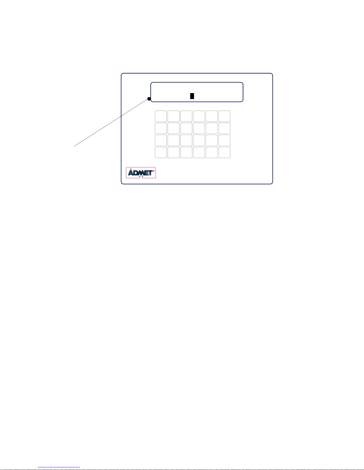
Figure 2.1 - Gauge Buster 2 Keypad and Screen Display.
Control Print 0
Zero (.)
Freeze
1
4
Store
Utils
23
56
ENT
Start
È
Jog Dn
Ç
Jog Up
Method
Test 7
ID# 89
ESC
Stop
Report
Options
Setup
(-)
Disk
Test Rate
136745 LB
M3
Gauge Buster 2 781-769-0850
www.ADMET.com
24 key tactile keypad
Active Test
Method L- - - - - - - - - -- - - - - - -H
2 line x 16 character LCD with 3/8" H characters
Live Load
Display while specimen
under test: Live Load and
Load Rate Pointer shown
between High and Low
Rate Limits.

-8-
Gauge Buster 2 Operations Manual ADMET, Inc.
3.0 THE MENUS and KEYS
3.0.1 Test Method Specific Menu Selections
The Gauge Buster 2 can store up to 6 test methods.
These menu items apply to the current selected test method and need to be set for each test method being
used.
Use the <Setup> key to access the Setup Menu. Use
number keys and Up/Down keys to navigate the menu.
1) Specimen Type - Available Geometries: Cylinder,
Round, Flat, Cube, Beam Ctr, Beam 3rd, X-Area
2) Log Threshold - Start logging data threshold
3) Sample Break
a) Percentage of Peak
b) Arm Sample Break Threshold
4) Engineering Units
1) Force - Lbf, N, kN, kg
2) Stress- psi, kPa, MPa, ksc
3) Length- in, mm, cm
4)Age- Hours, Days
5) Rate Display -Available: Pointer, Force/sec, Force/min,
Stress/sec, Stress/min, Extn/min, Extn/sec, Extn.
6) Auto Store - Results, XY Data, Both
7) Load Cell - Select one of up to 6 calibrated cells.
8) Extn (option)
9) AuxCh (option)
Test Method
Select Test Method (1-6)
Setup Menu
Use the <Report Opt> key to access the Report
Options Menu. Use number keys and Up/Down keys
to navigate the menu. Available test report options
are:
Operator ID
Cylinder Cap Type
Specimen Age
Specimen Weight
Cylinder Break Type
Cylinder Correction Factor
Average Rate
Yield by Halt of the Pointer
ASTM C469 Modulus (option)
ASTM C469 Poisson's (option)
Report Options Menu
NOTE: This menu is only active in units enabled for
operating the MegaForce Automatic Pumping System.
Use the <Control> key to access the Control Menu.
Use number keys and Up/Down keys to navigate the
menu.
1) Test Rate
2) Preload
3) Preload Rate
4) Start Control
a) Start Control Load
b) Start Control Speed
5) Hold Load
6) Control Gains (password protected)
a) Proportional Gain
b) Integral Gain
c) Derivative Gain
d) Gain Shift
e) Shift1 (% FS)
f) Shift2 (% FS)
Control Menu (Option)
Use the <ID#> key to access the ID number Menu.
Follow the prompts to input the following information.
Specimen ID
Specimen Dimensions
Operator ID (if active)
Cylinder Cap Type (if active)
Specimen Age (if active)
Specimen Weight (if active)
ID# Menu

-9-
Gauge Buster 2 Operations Manual ADMET, Inc.
3.0.2 Global Menu Selections
These menu items are not test method specific.
UTILS Menu
Use number keys and Up/Down keys to navigate
the menu.
1) Clear Results
2) Set Date/Time
3) Ck Trans & IO
4) Install Def
5) Supervisor (On/Off)
6) Calibrate
-11-
Print Menu
Use number keys and Up/Down keys to navigate
the menu.
USB Print (option to local USB Printer)
1) Current Test
2) Stored Tests
3) Individual Test
4) Print XY Plot
5) Test Method
6) Calibration
Disk Menu (Option)
Host PC
Use number keys and Up/Down keys to navigate
the menu.
1) XY Data -> Host
2) Results -> Host
3) Test Method -> Host
4) Calibration -> Host
5) Thumb Drive -> Test Method (Loads Test Method
from Thumb Drive)
6) Thumb Drive -> Calibration (Loads Calibration from
Thumb Drive)
Disk Menu (Option)
Flash (Thumb) Drive
Use number keys and Up/Down keys to navigate
the menu.
1) XY Data -> Disk
2) Results -> Disk
3) Test Method -> Disk
4) Calibration -> Disk
5) Disk -> Method (Loads Test Method from Thumb
Drive)
6) Disk -> Cal (Loads Calibration from Thumb
Drive)

-10-
Gauge Buster 2 Operations Manual ADMET, Inc.
Press the <Report Opt> key from the Indicating Screen to enter the Report Options/Analysis Menu. Use the
<ARROW> keys to scroll through the menu. Press the <NUMBER> keys to select the menu item. The
following items are found in the Report Opt Menu.
1.)Report Options. Choose which analyses to activate. Use <Arrow> keys to scroll through items and toggle
the 1) key to activate option. Available options include:
Oper ID: Operator ID.
CylCapType: Cylinder Cap Type
SpecAge: Specimen Age
Spec Wt: Specimen Weight
CylBrkType: Cylinder Break Type
CylCorFact: Cylinder Correction Factor
Statistics: Statistics
Avge Rate: Average Rate Calculation
Yld Halt: Yield by Halt of Force
Avge Rate: Average Rate Calculation
C469 Mod: C469 Modulus of Elasticity
C469 Pois: C469 Poisson's Ratio
2.)ReCalc Results. Recalculates all analyses.
3.2 The Report Opt Menu
Press the <Setup> key from the Indicating Screen to enter the Setup Menu. Use the <ARROW> keys to
scroll through the menu items. Use the <NUMBER> keys to select the menu item. The following functions
are provided in the Setup Menu.
1) Specimen Type. Select the specimen type for the sample to be tested. After selecting the type of
specimen, the appropriate dimensions are requested.
2) Data Logging. Specify the Logging Threshold (Log Thresh) and the Data Logging Rate (Log Rate).
Log Threshold is the force value at which data logging begins.
3) Sample Brk. Select the threshold for arming sample break (Brk Thresh) and sample break percent
age (Sample Break (%)). Sample Break is defined as a percentage of peak load and is used to define
the end of a test. If Break Threshold is 1000lb, Sample Break (%) = 10 percent and Maximum Load
seen during test is 100,000 Lb, then the Gauge Buster 2 will be armed for sample break when load
increases over 1000lbs and test will end (data logging stops, Max Load/Max Stress displayed) when
load drops below 10,000 lbs, which is 10% of the maximum of 100,000lbs.
4) Engineering Units. Used to select between load units of Lb, N, KN, and Kg, Stress units of PSI, Mpa,
Kpa and ksc and rate units on a per second or per minute basis. Length units of in, mm and cm and
Age units of days and hours.
5) Rate Display. a.)Choose type of load rate display with Rate- selection : Select between Load/min,
Load/sec, Stress/min, Stress/sec OR Pointer. Pointer displays the load rate relative to defined lower
and upper limits. The lower limit is marked as an "L" on the rate display line and the upper limit is
marked as an "H" on the rate display line during a test.
b.)Also choose average time period for load rate calculation with AvgTm.
6) Auto Store. If Store is set toAUTO, the results are automatically written to the results buffer and the
specimen ID# is incremented when sample break is detected. If Store is set to MAN, it is necessary to
press the <STORE> at the end of test to save the test results to memory and increment the specimen
ID#.
7) Load Cell-. Use to select load cell. You can select between valid load cell calibrations set up in
the calibration menu.
3.1 The Setup Menu

-11-
Gauge Buster 2 Operations Manual ADMET, Inc.
3.3 The Utils Menu
1)
2)
3)
4)
5)
6)
7)
Press the <Utils> key from the Indicating Screen to enter the Utils Menu. Use the <ARROW> keys to scroll
through the menu. Press the <NUMBER> keys to select the menu item. The following items are found in the
Utils Menu.
Clear Results. Erase all test results stored in the results buffer. Make sure you have printed the data before
erasing memory.
Set Date and Time.
Ck Trans-DOUT and I/0. This function displays Input/Output status as well as the transducer readings in A/D
counts. PossibleA/D values are between -2,200,000,000 and +2,200,000,000.
Install Defaults. Used to put all setup parameters in a known default state. Installing defaults DOES NOT
effect any of the calibration information.
Supervisor. Select Supervisor ON or OFF. This is a password protected field. With Supervisor set to ON,
the user has full access to all menus. With Supervisor set to OFF, the user has access to the ID# field
only.
Stream. Toggle to ON to stream XY data to GageSafe Data Exchange program.
Calibrate. Calibrate a load cell according to ASTM E4 standards. See Section 5.0 for calibration proce-
dures.
Edit Calibration Points. This function allows the calibrator to modify the load value for a given calibration
point.
NOTE: The calibrator can also editA/D counts in the calibration. Select Install Def from the Utility menu. The
screen will read 1)Install; ESC)Exit. Press the "9" key to get into the edit A/D count screens.
Press the <ID#> key from the Indicating Screen to input the Specimen ID number. The Specimen ID number
can be 8 digits long. Input the Specimen ID number and press <ENTER> to accept . Note: The Specimen
ID number will be automatically incremented after the current test result has been printed or stored. You will
then be prompted to enter dimensional information for your selected specimen. Prompts for any items en-
abled in the Report Options menu will follow the specimen dimensions prompt.
3.4 The ID# Menu
3.5 The Print Menu
NOTE: This menu is used to print hard copy printouts to an HP compatible USB printer.
This feature is not included with the standard Gauge Buster 2. The USB printer option and the printer are
purchased separately.
Press the <Print> key from the Indicating Screen to enter the Print Menu. Use the <ARROW> keys to
scroll through the menu. Press the <NUMBER> keys to select the menu item. The following items are
found in the Print Menu:
1) Current Test. Transmits the current test result to the printer.
2) Stored Tests. Transmits stored test results to the printer.
3) Select Test. Transmits one specified test result to the printer.
4) Prn XY Plot. Transmits XY plot to the printer.
5) Test Method. Transmits the current test method to the printer.
6) Calibration. Transmits calibrations to the printer.

-12-
Gauge Buster 2 Operations Manual ADMET, Inc.
3.6 The Disk (-) Menu
The Disk (-) Menu has two sub-menus:
1) Host PC
2.) Thumb Drive
Host PC
The Host PC menu contains options for transmitting data to the GageSafe Data Exchange Program, which is
not included with the Gauge Buster 2 and must be purchased separately.
NOTE: You can upload test methods and calibrations from GageSafe as well. These actions are initiated from
within the GageSafe program and described in the GageSafe manual.
The following items are found in the Host PC menu:
1) XY Data -> Host. Transmit XY data from the current test to GageSafe.
2) Results -> Host. Transmit stored test results to GageSafe.
3) Method -> Host. Transmit Test Methods to GageSafe.
4) Cal -> Host. Transmit calibration to GageSafe.
Thumb Drive
The Thumb Drive menu contains options for exchanging data with a USB Flash (Thumb) Drive.
NOTE: This feature is only enabled if you have the Flash (Thumb) Drive option. It is not included with stan-
dard Gauge Buster 2. The USB flash drive option and the flash drive are purchased separately.
The following items are found in the Thumb Drive menu:
1) XY Data -> Disk. Transmit XY data from the current test to Thumb Drive.
2) Results -> Disk. Transmit stored test results to Thumb Drive.
3) Method -> Disk. Transmit Test Methods to Thumb Drive.
4) Cal -> Disk. Transmit calibration to Thumb Drive.
5) Disk -> Method. Upload test methods from Thumb Drive to Gauge Buster 2.
6) Disk -> Cal. Upload calibrations from Thumb Drive to Gauge Buster 2.

-13-
Gauge Buster 2 Operations Manual ADMET, Inc.
4.0 OPERATION
4.1 How to Setup a Test
You can store up to 6 test methods in the Gauge Buster 2. Test methods can be transferred to and from the
GageSafe Data Exchange software or a USB Flash (Thumb) drive in units that are equipped with these
options.
Section 4.1 describes how to setup for a test. Section 4.2 describes how to perform a test and store the
results to memory. Section 4.3 describes how to generate test reports. Section 4.4 describes how to down-
load the stored test results to a remote PC.
Step 1: Press <SETUP> from the Indicating Screen. From the SETUP Menu select the following and enter
values for each.
Specimen Type. Specimen type to be tested, Cylinder, Cube, Beam Ctr, Beam 3rd, Round or Area.
Data Logging. Set Logging Threshold. When the logging threshold load value is exceeded, data logging
begins and the test starts.
Set the Data Logging rate appropriate to your test.As data logging rate increases, total test
time buffer decreases. The total test time for each data logging rate is displayed in menu i
tem.
Sample Break. Set the Break Threshold to a load value where you want the Gauge Buster 2 to be armed
for sample break .This value needs to be greater than the data logging threshold.
Set Sample Break % to value to where you want to define the end of test.
For example, ff Break Threshold is 1000lb, Sample Break (%) = 10 percent and Maximum
Load seen during test is 100,000 Lb, then the Gauge Buster 2 will be armed for sample
break when load increases over 1000lbs and test will end (data logging stops, Max Load/
Max Stress displayed) when load drops below 10,000 lbs, which is 10% of the maximum of
100,000lbs.
Rate Display Set Rate Display to force/sec; force/min; stress/sec; stress/min or Pointer.
If pointer then set the low rate and the high rate:
Rate-Lo.Enter the lower rate limit, marked as "L" in the rate display.
Rate-Hi. Enter the upper rate limit, marked as "H" in the rate display.
NOTE: If Specimen Type set to Cylinder, then lo and hi rate values automatically set to appropriate value as
specified by ASTM C39.
Engineering Units. Set load units to Lb, N, KN or Kg. Set stress units to psi, kPa, MPa, or ksc. Set length
units to in, mm or cm, Set Age units to Days or Hours
Auto Store Select if you want to automatically store every test result.
Load Cell. Select the load cell number if necessary.
See Section 3.1 for more information.
Step 2: Press <UTILS> from the Indicating Screen. Clear results from memory. Note: If the stored results
are important, print before clearing. See Section 3.3 for more information.
Step 3: Press the <ID#> from the Indicating Screen. Input the specimen ID#. The specimen ID# will auto-
matically increment after the current test is stored. If any Report Options have been turned ON, additional
prompts will follow.

-14-
Gauge Buster 2 Operations Manual ADMET, Inc.
Control Print 0
Zero (.)
Freeze
1
4
Store
Utils
23
56
ENT
Start
È
Jog Dn
Ç
Jog Up
Method
Test 7
ID# 89
ESC
Stop
Report
Options
Setup
(-)
Disk
4.2 How to Perform a Test and Save Results
If the steps in Section 4.1 were followed, you are now ready to perform a test. The current test settings are
saved in permanent memory and will not change unless they are modified by the operator.
Step 1: Insert the specimen in the machine and move the crosshead to the desired starting position. If using
a hydraulic machine, float the piston by moving off it's stop.
Step 2: Press the <ZERO> key to tare any residual load from the readout.
Step 3: Begin loading the specimen. Once the load exceeds the start test threshold value, the lower display
line will change to the specified rate display (load/stress rate or pointer). Once the load exceeds the break
threshold the Sample Break detector is armed.
Step 4: Once sample break is detected the test is complete and the lower display line will show peak load. If
Auto Store is turned ON, the results will be saved to memory. If Auto Store is turned OFF, press <STORE> to
save the current test results. Note: If you do not press <STORE> before pressing <ZERO> or the start of a
new test, the results will be lost.
To continue running tests, repeat Steps 1, 3, 4.
NOTE: The Gauge Buster 2 is designed to operate in a "hands free" mode. This means that once it has
been setup and properly zeroed, the operator should not have to touch the keypad. If a test result is stored,
the specimen ID# will automatically increment.
4.2.1 Indicator Live Screen During Test
READY and TESTING are the two possible Indicator Modes.
Figure 4.2.1 - The Live Indicating Screen Testing.
L- - - - - - - - - -- - - - - - -H
Display while specimen
under test: LiveLoad and
Load Rate Pointer shown
between High and Low
Rate Limits.
136745 LB
M3
Gauge Buster 2 781-769-0850
www.ADMET.com
24 key tactile keypad
2 line x 16 character LCD with 3/8" H characters
Live Load
Test Rate
Active Test
Method

-15-
Gauge Buster 2 Operations Manual ADMET, Inc.
Control Print 0
Zero (.)
Freeze
1
4
Store
Utils
23
56
ENT
Start
È
Jog Dn
Ç
Jog Up
Method
Test 7
ID# 89
ESC
Stop
Report
Options
Setup
(-)
Disk
Control Print 0
Zero (.)
Freeze
1
4
Store
Utils
23
56
ENT
Start
È
Jog Dn
Ç
Jog Up
Method
Test 7
ID# 89
ESC
Stop
Report
Options
Setup
(-)
Disk
Gauge Buster 2
Figure 4.2.2 - The Live Indicating Screen End of Test/Ready Mode.
20 LB
781-769-0850
www.ADMET.com
24 key tactile keypad
Display after specimen
break detected: Live Load
is displayed on the first line
and Peak Load and Peak
Stress toggle automatically
on the second line.
M3
Active Test
Method PEAK 156829 LB
2 line x 16 character LCD with 3/8" H characters
Live Load
Peak Load/
Stress
A data transfer cable and GageSafe Data Exchange Software manufactured by ADMET is required to
download data to a remote PC. Refer to the GageSafe Data Exchange program manual for downloading
data to a computer.
4.3 Printing Test Reports to a HP compatible USB Printer
4.4 Download Test Results to a Remote PC
If the steps in Section 4.2 were followed, a test report containing all of the results stored to memory can be
obtained.
NOTE: This feature is not included with the standard Gauge Buster 2. The USB printer option and the printer
are purchased separately.
Step 1: Press <PRINT> from the Indicating Screen to see available print options.
Print current test, stored tests, one specified stored test, or XY plot to printer
More information in section 3.5
4.5 Download Test Results to a USB Flash (Thumb) Drive
NOTE: This feature is not included with the standard Gauge Buster 2. The USB Flash Drive option AND the
Flash Drive are purchased separately.
Step 1: Press <Disk (-)> from the Indicating Screen to see available Thumb Drive options.
More information in sectiion 3.6.
4.2.2 Indicator Live Screen End of Test/Ready Mode

-16-
Gauge Buster 2 Operations Manual ADMET, Inc.
You can calibrate up to 6 load cells to the Gauge Buster 2. There can be up to 10 points in each calibration.
Step 1: Turn on the system and allow it to run for 10 minutes before calibrating.
Step 2: Select the Engineering Units for calibration from the SETUP Menu. See Section 3.1 for more
information.
Step 3: Select <7> Calibrate from the Utils Menu.
Step 4: Enter the password. Contact ADMET technical support if you have lost the password.
Step 5: Enter the load cell number. Use zero if your system has only one load cell.
Step 6: Input the full scale range or the capacity of the machine. The range should be input in the currently
active engineering units.
Step 7: Input the resolution or minimum load increment.
Step 8: Press <1> Set Cal Points to enter the measure mode or <ESC> to exit.
NOTE: If you decide to exit the Calibration Menu at this time the values entered for Full Scale and Resolution
will be saved.
Required Information Before Continuing Calibration
The program will enter the measurement mode if <1> is pressed in Step 8. During this mode, the technician
can take up to ten calibration point readings (a minimum of 2 points is required).
NOTE: The first calibration point must be at zero load.
It may be beneficial to take a few more calibration readings in areas of greatest inaccuracy. The number
next to "Set PT No" on the display will indicate how many calibration readings have been taken. As the
calibration points are entered, write down the corresponding load value. After all ten calibration points have
been taken, or the <STORE> key is pressed when using less than ten points, the Gauge Buster 2 automati-
cally switches to engineering input mode. Input the load value corresponding to each calibration point reading
stored. The calibration points are stored sequentially. The first point is zero followed by the second, third and
so forth. Once an engineering unit value has been entered for each calibration point stored, the unit will
automatically save the calibration.
NOTE: Display will prompt for Set PT No 0 when setting the first point. The first point in the calibration MUST
be zero load. After all of calibration points have been stored, the first Engineering unit value entered will be 0.
The prompt for this will be PT(1).
Step 9: Unload the machine or place the transducer at its zero point. If calibrating a hydraulic machine, float
the piston before taking any readings. Press <ENTER> to take the zero reading. The left side of the display
will indicate PT1 has been read.
Step 10: Load the machine to a desired load and press <ENTER> to set a calibration point (voltage measure-
ment). The voltage value is NOT displayed but it has been saved to nonvolatile memory. Write down the
corresponding engineering unit value for each calibration point. Repeat this step until all readings are taken.
5.0 CALIBRATION
5.1 How to Calibrate Analog Transducers
Refer to Section 7.1 for details on transducer connections.

-17-
Gauge Buster 2 Operations Manual ADMET, Inc.
Step 13: To verify the calibration, exit out to the Indicating Screen and apply specific loads to the machine
and compare the reading on the indicator with the standard.
Step 14: If you choose to adjust one or some of the calibration points, use the Edit Calibration function from
the Utils menu. This function will allow you to edit load values for one, some or all calibration points without
forcing you to repeat Steps 2-12.
5.2 What Occurs During Calibration
The calibration procedure allows up to ten calibration points to be entered. Each successive pair of points is
connected by a straight line and the slope of each line is the calibration scale factor used for that region. This
results in a piecewise linear function which maximizes accuracy.
Step 11: Press <STORE> to exit the measurement mode if fewer than ten calibration points are used. The
program will automatically proceed from Step 10 to Step 12 after the tenth reading.
Step 12: Input the corresponding engineering unit value for each measurement point. After all values have
been entered, the program will automatically generate the corresponding scale factors and store them to
permanent memory.
DONE! READY TO VERIFY CALIBRATION
5.3 Saving Calibration Data
All calibration data can be transferred to and from the GageSafe Data Exchange software or a USB Flash
(Thumb) drive in units that are equipped with these options.
Calibration data can also be printed to HP compatible USB printer in units that are equipped with this option.

-18-
Gauge Buster 2 Operations Manual ADMET, Inc.
6.0 TROUBLESHOOTING
Gauge Buster 2 Troubleshooting
ProblemDescription Possible Causes Action
Not holding peak load
OR
Not tracking load while
machine actually loading and
breaking sample.
OR
Rate Bar not being
displayed.
Sample break threshold
and sample break %
settings
NOTE: The Gauge Buster 2 digital goes into TESTING
MODE when the actual load exceeds the programmed load
threshold value. When the Gauge Buster 2 Digital is in the
TESTING MODE, tehe live load is displayed on the upper
right and the load rate bar or load rate is displayed in the
bottom of the display. If you do not see the load rate bar or
the numeric load rate in the bottom display then you are NOT
in the testing mode and you need to look at your data logging
threshold value.
Ensure that the Break Threshold (Sample Brk menu item in
the Setup menu) is set to a value that is appropriate for the
test. Break Threshold is the point where the Gauge Buster 2
digital is armed for sample break. If the break threshold is too
low then a load drop in the early part of the test could trigger
the Gauge Buster 2 to detect premature specimen break (end
of test) and stop logging data. For example, if the Break
Threshold is set to 10lbs (much too low) and the sample break
percentage is set to 50% and the load climbed to 20lbs and
then dropped to 10lbs the Gauge Buster 2 would detect
sample break, stop logging data and report a peak load of
20lbs.
Ensure that Sample Break (SETUP, End of Test menu) is set
appropriately. Sample Break is defined as a percentage of
peak load and is used to define the end of a test. If Sample
Break = 10 percent and Peak Load = 100,000 Lb, then the
test will terminate when the load drops below 10,000 Lb.
Setting sample break percentage to 0 disables it so the Gauge
Buster 2 will continue logging data until the test buffer is full. If
the sample break percentage is set too high then end of test
can be triggered early.
Applying Load too quickly
after taring Gauge Buster
PLUS
NOTE: The Gauge Buster 2 is designed for hands-free
operation. You should only need to zero the digital once. It is
not necessary and NOT recommended to zero the digital prior
to each test. Doing so can prevent the digital from going into
Testing Mode and not recording the peak load. If you do not
see the rate bar or load rate display on bottom line of the
display it then the digital is not going into testing mode.
Ensure that you are that you are waiting at least 3 seconds
after zeroing digital before running a test (applying load to your
break machine).

-19-
Gauge Buster 2 Operations Manual ADMET, Inc.
Gauge Buster 2 Troubleshooting (cont'd)
ProblemDescription Possible Causes Action
Load reading wrong
Calibration
Ensure that correct load calibration is selected. The Active
Calibration # is displayed in the upper left of the live screen.
The Gauge Buster 2 can store up to six load cell calibrations.
Analog/Digital Electronics Contact ADMET technical support.
Excitation Voltage bad. Contact ADMET technical support.
Load Transducer Cable Replace/fix transducer cable
NOTE: refer to See Electrical/Mechanical Data section of
this manual for cable wiring information.
Load Transducer Replace load transducer
Stress reading wrong Specimen Information
Stress is a calculated value. It is equal to the load divided by
the programmed specimen cross-sectional area.
Ensure that Specimen Type and specimen dimension
information is correct in the SETUP menu.
Load reading unstable
Calibration
Ensure that there is valid calibration in selected load channel.
A valid calibration has at least two points, the first point
MUST be zero, appropriate full scale and resolution settings,
and a good A/D count span between the points in the
calibration.
Analog/Digital Electronics Contact ADMET technical support.
Excitation Voltage bad. Contact ADMET technical support.
Load Transducer Cable
Ensure that cable gain strap is properly wired for transducer
being used.
Replace/fix transducer cable
NOTE: refer to See Electrical/Mechanical Data section of
this manual for cable wiring information.

-20-
Gauge Buster 2 Operations Manual ADMET, Inc.
7.0 ELECTRICAL/MECHANICAL
DATA
Analog Channel Connections
Analog-Load Input
Analog Excitation:
pins 9 & 10 (+Exc & AGND)
5 Vdc
Analog Inputs: pins 1 & 2 (+/- IN)
Analog Input Range:
up to 2.5 mv/v Tie pin 3 to pin 12
up to 4.5 mv/v Tie pin 4 to pin 12
+/- 5 V No Connection
User definable Tie <25 ppm/C resistor
between pin 11 & pin 12.
Gain = 1 + 50000/Rg.
Connect all shields to chassis.
Transducer Identification (Contact Factory)
9
10
11
12
1
2
3
4
5
AGND
IN+/SHUNT
GS1
GS2
6
7
8
13
14
15
IN-
TR TYPE
ENC 5V
DGND
+Exc
AGND
GS3
GS0
SHUNT
ENC A
ENC B
DB15 Female
Figure 7.1.2 - Analog Transducer Pin Designation.
Figure 7.1.1 - Gauge Buster 2 Rear Connection Panel.
7.1 User Connections
Power
Switch
GaugeSafe Communication Port
Load/Enc Channel
Strain Channel
Not used
Not used
Printer
Port
(Optional))
Flashdrive
Port
(Optional))

-21-
Gauge Buster 2 Operations Manual ADMET, Inc.
7.4 Dimensions
9.25" 3.00"
8.50"
7.2 USB Port
7.3 Power (AC) Input
The USB port is used to transmit exchange data with either an HP compatible USB printer, GageSafe Data
Exchange software, or a Flash (Thumb) drive.
The Gauge Buster 2 Power requirements: 85 to 265 VAC (50 - 60Hz).
Table of contents
Popular Test Equipment manuals by other brands


Redtech
Redtech TRAILERteck T05 user manual

Venmar
Venmar AVS Constructo 1.0 HRV user guide

Test Instrument Solutions
Test Instrument Solutions SafetyPAT operating manual

Hanna Instruments
Hanna Instruments HI 38078 instruction manual

Kistler
Kistler 5495C Series instruction manual

Waygate Technologies
Waygate Technologies DM5E Basic quick start guide

StoneL
StoneL DeviceNet CK464002A manual

Seica
Seica RAPID 220 Site preparation guide

Kingfisher
Kingfisher KI7400 Series Training manual

Kurth Electronic
Kurth Electronic CCTS-03 operating manual

SMART
SMART KANAAD SBT XTREME 3G Series user manual

Agilent Technologies
Agilent Technologies BERT Serial Getting started