Adonis JX-5G User manual

ADONIS
FLEXIBLE JUMBO MOBILE MICROOHONE
JX-5G
INSTRUCTION MANUAL
Space Electric Corporation
OSAKA, JAPAN

SEC
- 2 -
FLEXIBLE MOBILE MICROPHONE JX-5G
INSTRUCTIONS
Thank you very much for your purchase of “ADONIS” Flexible Jumbo Mobile Microphone Model JX-5G.
To enjoy this unit satisfactorily, please read the instructions carefully and we hope you can
enjoy using this microphone for a long time.
FEATURES:
●The Uni-Directional Microphone serves to reduce the background noise.
●The flexible gooseneck is the withstand vibration type.
●Transmitting/Receiving Selector Switch is mountable with the gear-shift lever for safety
driving.
●TX/RX Switch Box is provided with UP/DOWN Switches and LED Transmitting Indicator.
●Variable microphone sensitivity due to Output Level Adjusting volume built-in.
●Provided with Non-Modulation Prevention Circuit with alarm sound.
●Useable with various kinds of Transceiver by connecting with conversion cables optionally
available.
●Useable with microphone cable equipped with power feeding line (“D”series cables).
PART NAMES: (Fig.1)
①Microphone with Flexible Pipe
②Mounting Bracket
③Mic. Cord with RCA(Pin) Plug
④Input/Output Cord
⑤Mic. Input RCA(Pin) Jack
⑥8P Interconnecting Jack
⑦Control Switch Box
⑧UP Switch (Blue)
⑨DOWN Switch (Grey)
⑩Output Adjusting volume
⑪PTT (TX/RX) Switch
⑫LED TX Indicator
⑬Power Feeding Line
⑭Conversion Cable(Optional)
Accessories:
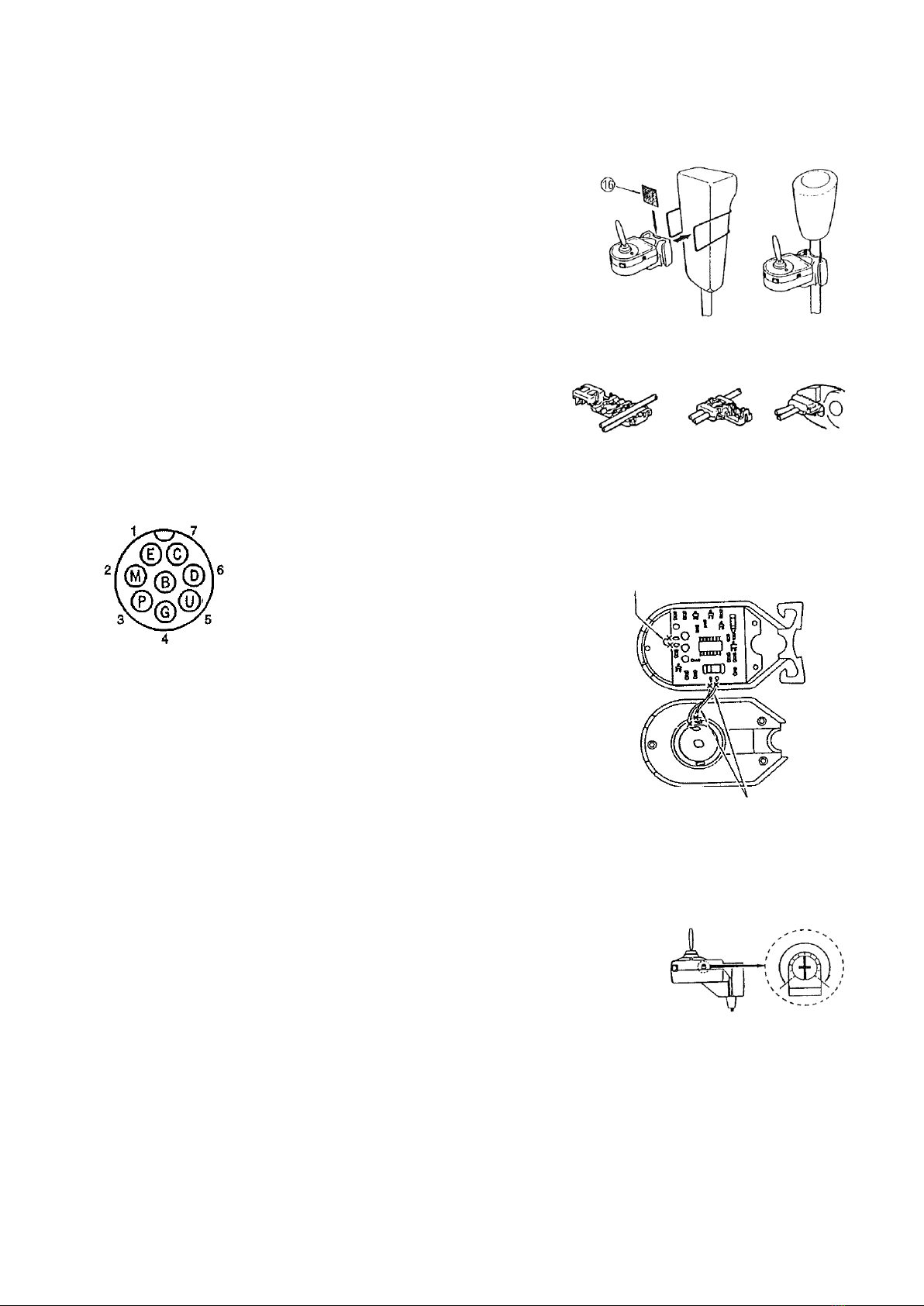
⑮Rubber Bands(φ40, φ60, φ75) ⑯Rubber Plate ⑰Connector for Power Feeding Line
⑱Driver for Output Adjusting volume ⑲Windscreen(Sponge)
HOW TO MOUNT AND CONNECT: (Fig. 5 Example of Mounting)
1. Fasten the Mounting Bracket②to Sun-visor, or, mount
onto convenient place. (See Fig. 5)
2. Mount the Control Switch Box⑦with Rubber Band⑮to
the gear-shift lever. In case of need, place the Rubber
Plate⑯in-between the control box and shift lever.
(See Fig. 2)
3. Plug the Mic. Cord with RCA Plug③into Mic. Input RCA
(Pin ) Jack⑤connected with Input/Output Cord.
4. Connect the suitable conversion cable⑭,optionally
available, to 8P interconnecting Jack⑥connected to
Input/Output Cord④and transceiver correctly.
(The Conversion Cable has the direction for connecting.)
SEC
- 3 -
5. The Power Feeding Line⑬should be connected to the (+)side power source of transceiver
with Power Feeding Connector⑰provided. (See Fig. 3)
HOW TO MOUNT THE Switch Box⑦:(Fig.2)
1. Fix the Switch Box to gear-shift lever with the rubber band
strongly.
2. If not stable, insert the rubber plate⑯in-between switch
box and shift-lever.
HOW TO CONNECT POWER FEEDINNG CONNECTER⑰:(Fig.3)
1. Put the(+) side power of transceiver and Mic. Power cord
⑬on grooves in the connecter.
2. Fix them tentatively.
3. Press the insulation cover down to be locked with
players.
(1) (2) (3)
8P ADONIS TYPE TERMINAL CONNECTION
(8PInterconnecting Jack⑥)(Fig.4)
1. E: Earth(Mic. Signal)Shield
2. M: Mic. Signal Yellow
3. P: PTT(press to talk) Red
4. G: Earth(for PTT) Purple(Blue)
5. U: Up Green
6. D: Down White
7. C: U/D Common Orange
8. B: DC Power Feeding (+) Gray
HOW TO USE:
●Set the PTT switch⑪to “T” for transmitting and to “R”
for receiving. The LED TX indicator⑫will light up when
TX condition.
●The UP switch⑧and the DOWN switch⑨are the same
functions as those of the microphone provided with
transceiver. (Please read the instruction book for
details about this function.)
●Keep the distance of 10cm or less between mouth and microphone.
●The microphone output level is factory-preset to optimum Level.
●But, when you need optimum modulation to your transceiver, please
readjust it. Rotate the adjusting volume⑩to clockwise with screw
driver provided carefully under monitoring by local station. (The
maximum rotation angle is 100°each to the right and left side from
center position. Please make adjustment carefully and slowly.)
NON-MODULATION PREVENTIONCIRCUIT:
In case you set the PTT switch⑪to transmitting mode without any intention. the condition of
Non-Modulation will continue and it may cause trouble for other stations. TO prevent such a
condition, the alarm circuit built-in will activate after 2.5 minutes continuous transmitting
with alarm sound. After 30 seconds sounding, the condition will be reset to receiving mode
automatically. But after changing into receiving mode automatically, the alarm sounds out and
LED Indicator also lights up without stopping and going out. Please refer to the (Fig. 6) for
cancelling the Non-Modulation Prevention Circuit and Alarm sound.
HOW TO CANCEL THE NON-MODULATION
PREVENTIONCIRCUIT (Fig.6)
Remove the 3 screws on the bottom of
switch box and modify it as below.
Cut the jumpering wire for cancelling
the Non-Modulation Prevention
Circuit.
Cut the Yellow Wires for cancelling
the Alarm Circuit.
(Fig7)

SEC
- 4 -
RE FEEDBACK NOISE:
When transmitting with high power, there are possibilities to have abnormal modulation
interference with offensive sound and other noise. In such a case, the bad matching between antenna
and coaxial cable may cause the problems i.e., the Standing Wave effects onto microphone cable.
To get better condition, please do not place the microphone cable in parallel to the antenna
coaxial cable. Also please check the SWR between antenna and transceiver.
CAUTIONS:
●Please do not beat the microphone when adjusting the output level and at QS0.
●Regarding the microphone interconnecting cables (Conversion Cables), please be sure to use
“ADONIS”standard cables, optionally available.
●Please keep this microphone away from high temperature and moisture area.
●The design and specifications are subject to change without advance notice.
SPECIFICATIONS:
●Uni-Directional Condenser Microphone unit :1piece
●The length of Microphone with flexible pipe :59cm
●Microphone Cord length :5m
●In& Output Cord :70cm
(with 8P interconnecting Jack and RCA Jack)
●Matching Output impedance :500Ω~100kΩ
●Output voltage :0~50mV(rms)
●Power voltage (1)Power Feeding Line (Red ) :DC12~15V
●(2)”D”Series Conversion Cable:DC5~9V
●The Size of Switch Box :44(H)×38(W) ×67(D)mm
●Weight :400g
(ACCESSORIES ATTACHED)
●Windscreen(Sponge)Blue :1piece
●Rubber Bands(φ40,φ60,φ75) :each 1piece
●Connector for Power Feeding Line (Red) :1piece
●Rubber Plate :1piece
●Driver for Output Adjusting volume :1piece
Table of contents
Other Adonis Microphone manuals


