●The link cable (SC-GU1-CC02) can be shortened with the
desired length. However, the cable cannot be extended.
HOW TO CHANGE THE LENGTH OF LINK CABLE (SC-GU1-CC02)
7
Procedure
①Use a flathead screwdriver (Blade width: 2mm or less) to push
the operating lever (white) located at the wire inlet on the main
unit side connector of the link cable until it is locked.
②
③
Cut the link cable at the desired length.
Process the core length to 7 to 8mm in accordance with 'STRIP GAUGE' indicated
on the side of the connector, and twist the core
several times.
When using shielded wires, be sure to twist
the wire to a diameter of φ1.2mm or less.
④Insert the wire to the bottom of the wire inlet.
Check that the shielded part of the wire is
properly inserted into the wire inlet as well
as that the core end has passed through
the wire connection area as shown in the
right figure.
STRIP GAUGE
Core length:
7 to 8mm
Connector
Wire
Wire
connection
area
Shielded part
of wire
Wire inlet
Operating lever (white)
Releasing slot
Shielded wire
<Connector pin arrangement>
Core wire
Shielded wire
Not connected
Not connected
⑤Place the head of a flathead screwdriver
underneath the operating lever (white)
through the releasing slot, and lift the
screwdriver head.
If you hear a snap, the operating lever
(white) is returned and the wire is fixed.
⑥
⑦
Slightly pull the wire to ensure that the wire
is not loose.
Also, check that they are not in contact with
each other.
Fit the cover to the connector.
SETTING
8
●Follow the procedure given below for setting.
①
②
③
④
Mount this product and carry out wiring.
Carry out the address setting by using the DIP switch for address setting.
Carry out the communication-related setting by using the DIP switch for
communication setting.
Turn the power on.
Procedure
For communication conditions and commands, refer to 'Product specification'
and 'Communication command specification'.
Note: When the setting is changed after the power was turned on, be sure to press the reset switch.
Note: In case the upper communication error indicator (red) and the lower communication error
indicator (red) are mixed, each indicator blinks alternatively.
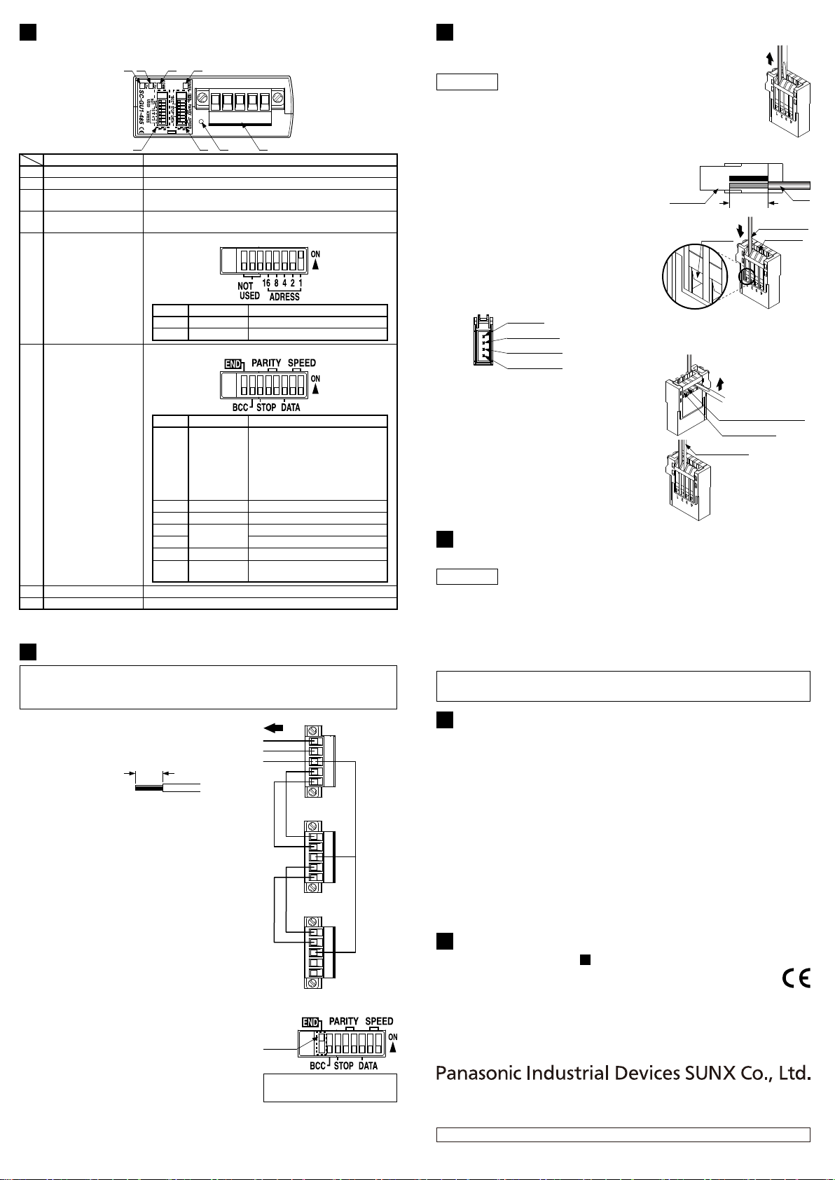
FUNCTIONAL DESCRIPTION
5
●Main unit / SC-GU1-485
①
⑦ ⑧⑥⑤
②③④
This is used when the upper controller or the main unit is mounted.
⑧
Terminal block connector
Makes the setting change valid.⑦Reset switch
⑥
DIP switch for
communication setting
0: Invalid, 1: Valid
0: Even number, 1: Odd number
5
4
8
Be sure to set the DIP switch
on the main unit at the
termination node to ON.
Be sure to set the DIP switch
on the main units other than the
termination node to OFF.
*:
0:
-
, 1: Termination
Termination
change
7 0: Invalid, 1: Valid
BCC check
6 0: 1bit, 1: 2 bitStop bit
Parity check
00: 9.6kbps, 01: 19.2kbps
10: 38.4kbps, 11: 57.6kbps
Communication
speed
2 to 1
3 0: 7 bit, 1: 8 bitData length
Description (0: OFF, 1: ON)Namebit No.
12347 6 58 bit No.
⑤
DIP switch for address
setting
Blinks when communication error between the main unit and
sensor amplifers occur.
④
Lower communication
error indicator (Red) (Note)
Blinks when communication error between PLC (Programmable Logic
Controller) and Master or Master and Slave, or command error occurs.
③
Upper communication
error indicator (Red) (Note)
Lights up during communication.②
Communication indicator (Green)
Lights up when the power is ON.①Power indicator (Green)
Designation Description
They are used for address setting.
Address setting
8 to 6
5 to 1
Not used.
-
DescriptionNamebit No.
12347 6 58 bit No.
CONNECTION WITH UPPER COMMUNICATION CABLE
6
Make sure that the power is off while wiring.
Be sure to use the specified communication cable.
The communication distance should be within the specification.
●
●
●
●
●
When the main units (SC-GU1-485)are
connected to each other, max. 31 nodes can be
connected. Wire them as shown in the right figure.
The wire process length should be 7mm.
●
●
●
●
Do not plate the wire connected to the terminal
block connector with solder etc., since the
connected wire may come off by loosening screws.
The tightening torque of the screws for wire
fixing should be 0.5N・m or less.
The screws of the flange part should be tighten
as well so that the terminal block connector
does not come off from the main body. The
tightening torque should be 0.5N・m or less.
For the communication cable, use a shielded
twist-pair cable. Furthermore, the shield should
be connect to the frame ground (F.G.).
To upper controller
A
B
A
B
F.G.
A
B
A
B
F.G.
A
B
A
B
F.G.
<1st node>
<2nd node>
<Termination node>
7mm
Note: The termination resistance is fit in the main unit.
Be sure that the DIP switch/termination select on the main unit in the termination node is set
to ON side, and the DIP switch/termination select on the main units other than the termination
node is set to OFF side.
●
●
●
Note that the frame ground (F.G.) terminal has
not been connected to inside the unit.
Be sure that the DIP switch/termination select
on the main unit in the termination node is set
to ON side, and the DIP switch/termination
select on the main units other than the
termination node is set to OFF side.
Connect a termination resistance (100Ω) in
the termination node.
<Recommended>
KPEV-S 0.5SQ×1P manufactured by Sumitomo Electric
Industries, Ltd.
Termina-
tion select
<DIP switch for communication setting>
Only the main unit of the
termination node is
ON.
This figure shows the
factory setting.
(
(
This figure shows the
factory setting.
(
(
INTENDED PRODUCTS FOR CE MARKING
10
●
●
The models listed under 'SPECIFICATIONS' come with CE Marking.
As for all other models, please contact our office.
Contact for CE
Panasonic Marketing Europe GmbH Panasonic Testing Center
Winsbergring 15, 22525 Hamburg,Germany
2
CAUTIONS
9
●
●
●
●
●
●
●
●
●
●
●
This product has been developed / produced for industrial use only.
Make sure that the power supply is off while wiring and adding the units.
Take care that wrong wiring will damage the sensor.
Verify that the supply voltage variation is within the rating including the
sensor amplifer.
In case noise generating equipment (switching regulator, inverter motor,
etc.) is used in the vicinity of this product, connect the frame ground (F.G.)
terminal of the equipment to an actual ground.
Do not use during the initial transient time (1 sec.) after the power supply is switched on.
This sensor is suitable for indoor use only.
Do not use this sensor in places having excessive vapor, dust, etc.
Take care that the product does not come in contact with water, oil, grease,
organic solvents, such as, thinner, etc., or strong acid and alkaline.
This sensor cannot be used in an environment containing inflammable or explosive gases.
Never disassemble or modify the sensor.
http://panasonic.net/id/pidsx/global
PRINTED IN JAPAN
Overseas Sales Division (Head Office)
2431-1 Ushiyama-cho, Kasugai-shi, Aichi, 486-0901, Japan
Phone: +81-568-33-7861 FAX: +81-568-33-8591
About our sale network, please visit our website.
© Panasonic Industrial Devices SUNX Co., Ltd. 2014


 User manual")

 User manual")


