ADRF SDR-ICS-43-6 User manual


Advanced RF Technologies, Inc.
ii
Information in this document is subject to change without notice.
Advanced RF Technologies, Inc. 1996-2017.
All rights reserved.
Please send comments to:
E-Mail: [email protected]
Phone: (818) 840-8131
(800) 313-9345
Fax: (818) 840-8138
Address:
Advanced RF Technologies, Inc.
Attention: Technical Publications Department
3116 Vanowen St.
Burbank, CA 91505
USA
www.adrftech.com

Advanced RF Technologies, Inc.
iii
REVISION HISTORY
CHANGE LIST
Version
Change list
Contents
Version
Author
Descriptions
Date
0.1
ADRF
Initial Release
11/07/ 2017
0.2
CK ,CHO
Update
05/14/ 2018
0.21
CK ,CHO
Update, Model name changed
07/10/ 2018
0.22
CK ,CHO
Update
07/18/ 2018
0.23
CK ,CHO
AWS Bandwidth Change
08/31/ 2018
0.25
CK ,CHO
7FN,WCS Band Add
11/29/ 2018
0.26
CK ,CHO
7FN Update
12/10/2018
0.28
CK ,CHO
Regulatory Warning Statement update
01/23/2019
0.28
CK ,CHO
Regulatory Warning Statement update
01/28/2019
0.29
CK ,CHO
600MHz update
11/10/2020

Advanced RF Technologies, Inc.
iv
TABLE OF CONTENTS
1. Introduction........................................................................................................................................................9
1.1 Highlights.....................................................................................................................................................9
1.2 Parts List.....................................................................................................................................................10
1.3 Repeater Quick View .................................................................................................................................11
1.4 Warnings and Hazards...............................................................................................................................12
2. Overview...........................................................................................................................................................16
2.1 LED.............................................................................................................................................................16
2.2 Host/Remote Switch..................................................................................................................................16
2.3 Ethernet Port .............................................................................................................................................16
2.3.1 AC Power ............................................................................................................................................17
2.3.2 Back Up Battery Port ..........................................................................................................................17
2.4 RF Ports......................................................................................................................................................18
3. Alarms...............................................................................................................................................................19
3.1 Message Board Alarms and Notification ...................................................................................................19
3.2 Alarms........................................................................................................................................................20
4. Installation ........................................................................................................................................................21
4.1 Installation Procedures..............................................................................................................................21
4.1.1 Wall Mount Procedure.......................................................................................................................21
4.2 Grounding..................................................................................................................................................21
4.3 Antenna Separation/Isolation....................................................................................................................22
4.4 Line of Sight ...............................................................................................................................................23
5. SDR-ICS-43 Web-GUI Setup ..............................................................................................................................24
5.1 Repeater/PC Connection Using Web-GUI..................................................................................................24
5.2 Status Tab ..................................................................................................................................................25
5.2.1 Band....................................................................................................................................................25
5.2.2 Power & Gain......................................................................................................................................25
5.2.3 Alarm ..................................................................................................................................................26
5.2.4 Message Board...................................................................................................................................26
5.2.5 Install, Power and modem Status.......................................................................................................27
5.2.6 Repeater Info / Repeater Location / Technical Support / Installer Contact Info................................27
5.3 Control Tab ................................................................................................................................................29
5.3.1 General Setting...................................................................................................................................29
5.3.2 System ................................................................................................................................................30
5.3.3 SNMP Trap..........................................................................................................................................30
5.3.4 Gain Control .......................................................................................................................................30
5.3.5 ICS Control..........................................................................................................................................31
5.3.6 Alarm Setting......................................................................................................................................31
5.4 Install Tab...................................................................................................................................................32
5.4.1 Install ..................................................................................................................................................32
5.4.2 SNMP..................................................................................................................................................33
5.4.3 Location..............................................................................................................................................33

Advanced RF Technologies, Inc.
v
5.4.4 Remote Ethernet Settings ..................................................................................................................33
5.4.5 Auto Installation.................................................................................................................................34
5.4.6 Date & Time........................................................................................................................................35
5.4.7 Band Selection....................................................................................................................................36
5.5 System .......................................................................................................................................................36
5.5.1 System: Account.................................................................................................................................36
5.5.1.1 System: Account- Account Management .................................................................................36
5.5.1.2 System: Account- New Account................................................................................................36
5.5.1.3 System: Account- Change Password.........................................................................................37
5.5.2 System- Closeout Package..................................................................................................................38
5.5.3 System- User Log................................................................................................................................38
5.5.4 System: Update ..................................................................................................................................39
5.5.5 System- Backup ..................................................................................................................................39
5.6 Help............................................................................................................................................................40
5.7 Logout........................................................................................................................................................40
6. Maintenance Guide for SDR-ICS-43 Repeater ..................................................................................................40
6.1 Periodic Inspection Checklist.....................................................................................................................40
6.2 Preventive Measures for Optimal Operation ............................................................................................40
6.2.1 Recommendations..............................................................................................................................40
6.2.2 Precautions.........................................................................................................................................40
7. Warranty and Repair Policy ..............................................................................................................................41
7.1 General Warranty ......................................................................................................................................41
7.2 Limitations of Warranty.............................................................................................................................41
7.3 Limitation of Damages...............................................................................................................................41
7.4 No Consequential Damages.......................................................................................................................41
7.5 Additional Limitation on Warranty............................................................................................................41
7.6 Return Material Authorization (RMA) .......................................................................................................41
8. Specifications....................................................................................................................................................42
8.1 Electrical Specifications .............................................................................................................................42
SDR-ICS-43_Sprint Specifications .........................................................................................................................42
SDR-ICS-43_Verizon Specifications.......................................................................................................................43
Mechanical Specifications .................................................................. 오류! 책갈피가 정의되어 있지 않습니다.
Environmental Specifications ............................................................. 오류! 책갈피가 정의되어 있지 않습니다.
Power Specifications .......................................................................... 오류! 책갈피가 정의되어 있지 않습니다.
Other Specifications ........................................................................... 오류! 책갈피가 정의되어 있지 않습니다.
9. Appendix...........................................................................................................................................................47
9.1 Shutdown Retry Logic................................................................................................................................47

Advanced RF Technologies, Inc.
vi
FIGURES
Figure 1-1 SDR-ICS-43 Repeater Parts List...........................................................................................................10
Figure 2-1 LED......................................................................................................................................................16
Figure 2-2 Host/Remote Switch...........................................................................................................................16
Figure 2-3 AC Input Port ......................................................................................................................................17
Figure 2-5 Battery Backup Port............................................................................................................................17
Figure 2-6 RF port................................................................................................................................................18
Figure 4-1 SDR-ICS-43 Wall Mount......................................................................................................................21
Figure 4-2 Ground Cable Connection ..................................................................................................................21
Figure 4-3 RF Repeater Oscillation ......................................................................................................................22
Figure 4-4 Line of Sight to the eNode-B(or BTS)..................................................................................................23
Figure 5-1 Login page ..........................................................................................................................................24
Figure 5-2 Status Tab...........................................................................................................................................25
Figure 5-3 Band Display.......................................................................................................................................25
Figure 5-4 Power & Gain Display.........................................................................................................................26
Figure 5-5 Alarm Display......................................................................................................................................26
Figure 5-6 Message Board...................................................................................................................................27
Figure 5-7 Install, Power and modem Status.......................................................................................................27
Figure 5-8 Repeater Info / Repeater Location / Technical Support / Installer Contact Info................................28
Figure 5-9 Control page.......................................................................................................................................29
Figure 5-10 General Setting...................................................................................................................................29
Figure 5-11 System ................................................................................................................................................30
Figure 5-12 Pop-up message when Reboot button is pressed..............................................................................30
Figure 5-13 Pop-up message when Factory Setting button is pressed..................................................................30
Figure 5-14 SNMP Trap..........................................................................................................................................30
Figure 5-15 Gain Control Setting ...........................................................................................................................31
Figure 5-16 ICS Control Setting..............................................................................................................................31
Figure 5-17 Alarm Threshold Setting.....................................................................................................................31
Figure 5-18 Install page .........................................................................................................................................32
Figure 5-19 SNMP..................................................................................................................................................33
Figure 5-20 Location Setting..................................................................................................................................33
Figure 5-21 Remote Ethernet Settings ..................................................................................................................34
Figure 5-22 Auto Installation.................................................................................................................................34
Figure 5-23 Repeater Location Info / Repeater Installer Info................................................................................35
Figure 5-24 Date & Time Setting ...........................................................................................................................35
Figure 5-25 Band Selection....................................................................................................................................36
Figure 5-26 System: Account- Account Management...........................................................................................36
Figure 5-27 System: Account- New Account .........................................................................................................37
Figure 5-29 System: Account- Change Password ..................................................................................................37
Figure 5-30 System- Closeout Package..................................................................................................................38
Figure 5-31 System- Closeout Package after the file upload.................................................................................38
Figure 5-32 System –User Log ..............................................................................................................................38
Figure 5-33 System –Update ................................................................................................................................39
Figure 5-35 System Backup....................................................................................................................................40
Figure 5-36 Help ....................................................................................................................................................40

Advanced RF Technologies, Inc.
vii
TABLES
Table 1-1 Parts List .............................................................................................................................................10
Table 2-1 RF Module LED Specifications ............................................................................................................16
Table 3-1 Message Board Alarms and Notification ............................................................................................19
Table 3-2 Alarms Threshold................................................................................................................................20
Table 8-1 Electrical Specifications ..........................................................................................................................

Advanced RF Technologies, Inc.
8
Terms and Abbreviations
The following is a list of abbreviations and terms used throughout this document.
Abbreviation/Term
Definition
AGC Automatic Gain Control
ALC Automatic Level Control
AROMS ADRF’ Repeater Operation and Management System
BDA Bi-Directional Amplifier
BTS Base Transceiver Station
CDMA Code Division Multiple Access
CFR Crest Factor Reduction
CP Cyclic Prefix
CW Continuous Wave (un-modulated signal)
DAS Distributed Antenna System
DL Downlink
eNode-B Evolved Node B which is the element in E-UTRA of LTE that is the evolution of the
element Node B in UTRA of UMTS
HPA High Power Amplifier
HW Hardware
ICS Interference Cancellation System
ILC Interference Level Control
IF Intermediate Frequency
LNA Low Noise Amplifier
LTE Long Term Evolution
MS Mobile Station
OFDM Orthogonal Frequency-Division Multiplexing
OFDMA Orthogonal Frequency-Division Multiple Access
PAR (PAPR) Peak to Average Power Ratio (Crest Factor)
PLL Phase Locked Loop
PSU Power Supply Unit
QAM Quadrature Amplitude Modulation
QPSK Quadrature Phase Shit Keying
RB Resource Block
RF Radio Frequency
SC-FDMA Single Carrier-Frequency Division Multiple Access
SQE Signal Quality Estimate
SW Software
eUE LTE User Equipment (LTE Mobile Station)
UL Uplink
VSWR Voltage Standing Wave Ratio

Advanced RF Technologies, Inc.
9
1. INTRODUCTION
The SDR-ICS-43-6 is an over-the-air high power repeater. SDR-ICS-43-6 supports 600, 700, SMR800+Cellular,
PCS, AWS, WCS, BRS-TDLTE band.
1.1 Highlights
Active ICS (Interference Cancellation System)
Band Selectable
Digital filtering with sharp roll-off (>50dBc @ ± 1 MHz from sub-band edge)
Remote monitoring and control capability using our Web-based GUI
95 dB of max gain and 43/30dBm (DL/UL) Composite power
Support optional internal modem box for remote access and alarming
Configurable network setting in order to interface with 3rd party external modem boxes
Adjustable ALC Output Power Level
Supports SNMP v1, v2, v3 (get, set & traps)
Incremental Automatic Shutdown/Resumption Time: SDR-ICS-43-6 gradually increases the time span between
automatic shutdown and resumption before it permanently shuts itself down
Versatility and Usability: SDR-ICS-43-6 gives total control to the user. Most of the control parameters, e.g.,
gain, output power, alarm threshold, etc. can be changed using the Web-GUI so that the user can adjust the
system perfectly to the given RF environment
Web-GUI connectivity via DHCP
Supports DHCP; No 3rd party GUI software required
Automated installation
Remote update support

Advanced RF Technologies, Inc.
10
1.2 Parts List
Table 1-1 Parts List
Label
Quantity
Description
SDR-ICS-43-6
A
1
SDR-ICS-43-6
B
1
Wall Mount Bracket
C
1
Mounting Bracket Template
D
1
AC Power Cable
E
1
Ethernet Cable (Crossover)
F
6
Anchor Bolt
G
1
Ground Cable
H
1
Documentation CD*
Optional SDR-ICS-43-6 Modem Package
I
1
Modem
J
1
Modem Connection Cable
K
1
19inch Chassis
L
1
Ethernet Cable (Crossover)
Figure 1-1 SDR-ICS-43-6 Repeater Parts List
* CD includes: User Manual, Quick-Start Guide, and Troubleshooting Guide
D
E
F
B
G
H
A
I
J
K
C
L

Advanced RF Technologies, Inc.
11
1.3 Repeater Quick View
DONOR
CPL(-20dB)
CPL(-40dB)
SERVICE
SERVER
LAN0
LAN1
BATTERY
AC IN
SDR-ICS-43-X
HOST
REMOTE
MODEM
ANT
DONOR
DUPLEXER
LNA0
LNA1
Server
Duplexer
Modem
CPL-20dB
Backup
Battery Port
AC Input Port
Modem
Antenna Port
LED
Host/Remote
Switch
SERVER
CPL-40dB
SDR-ICS-43-6
Advanced RF Technologies, Inc.
12
1.4 Warnings and Hazards
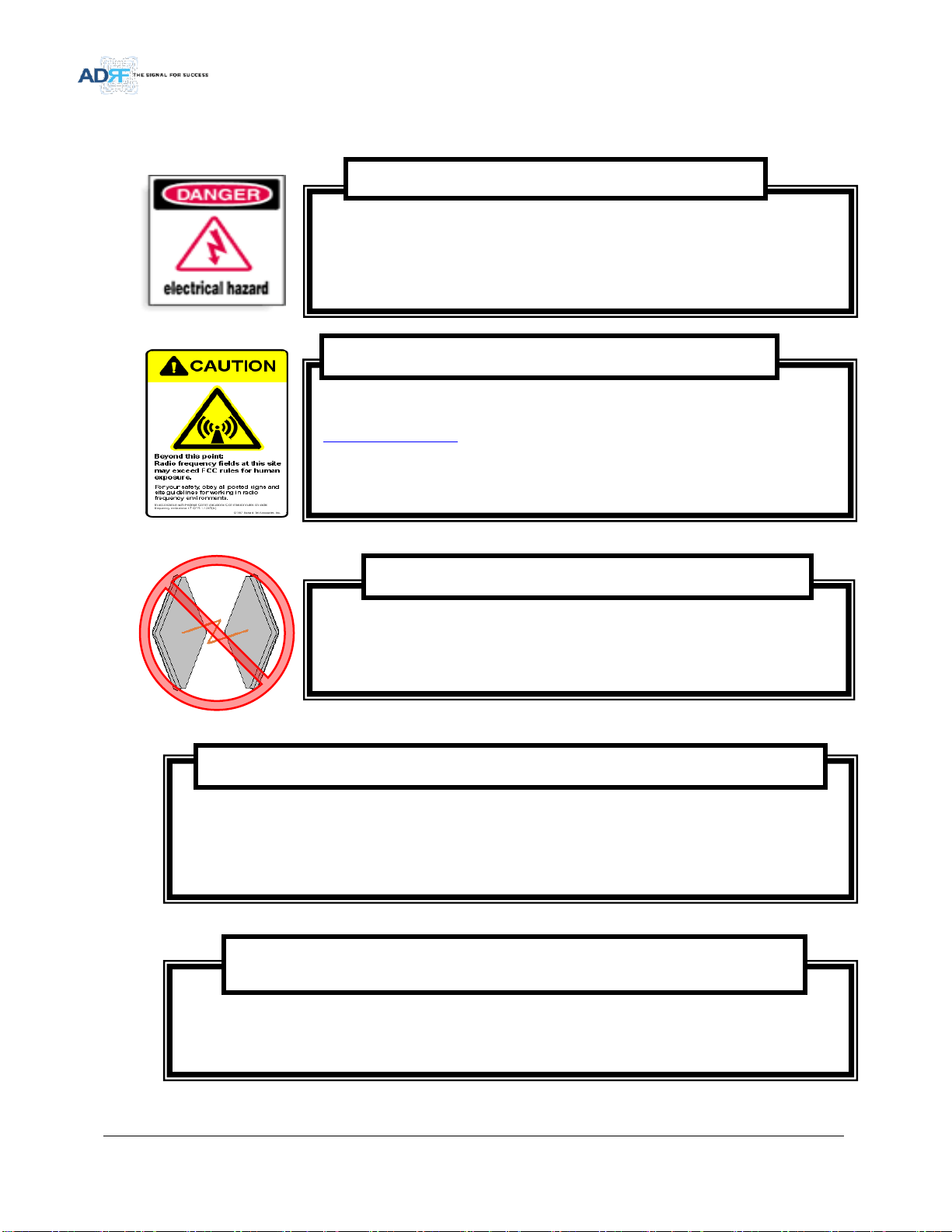
Opening the SDR-ICS-43-6 could result in electric shock and may cause
severe injury.
Working with the repeater while in operation, may expose the technician to RF
electromagnetic fields that exceed FCC rules for human exposure. Visit the FCC website at
www.fcc.gov/oet/rfsafety to learn more about the effects of exposure to RF electromagnetic
fields.
WARNING! EXPOSURE TO RF
Operating the SDR-ICS-43-6 with antennas in very close proximity facing each other could
lead to severe damage to the repeater.
WARNING! DAMAGE TO REPEATER
Actual separation distance is determined upon gain of antenna used.
Please maintain a minimum safe distance of at least UL:35cm, DL:180cm while operating near the donor and the server
antennas. Also, the donor antenna needs to be mounted outdoors on a permanent structure.
Use of unauthorized antennas, cables, and/or coupling devices not conforming with ERP/EIRP and/or indoor‐only
restrictions is prohibited.
RF EXPOSURE & ANTENNA PLACEMENT Guidelines
Opening or tampering the SDR-ICS-43-6 will void all warranties.
Home/ personal use are prohibited
WARRANTY
WARNING! ELECTRIC SHOCK
Advanced RF Technologies, Inc.
13
Lithium Battery: CAUTION. RISK OF EXPLOSION IF BATTERY IS REPLACED BY INCORRECT TYPE.
DISPOSE OF USED BATTERIES ACCORDING TO INSTRUCTIONS.
Ethernet Instructions: This equipment is for indoor use only. All cabling should be limited to inside
the building.
NOTE: This equipment has been tested and found to comply with the limits for a Class A digital
device, pursuant to part 15 of the FCC Rules. These limits are designed to provide reasonable
protection against harmful interference when the equipment is operated in a commercial
environment. This equipment generates, uses, and can radiate radio frequency energy and, if not
installed and used in accordance with the instruction manual, may cause harmful interference to radio
communications. Operation of this equipment in a residential area is likely to cause harmful
interference in which case the user will be required to correct the interference at their own expense.
FCC Part 15 Class A
Double Pole/Neutral Fusing.
CAUTION
Circuit Breaker Installation in the Box for Overcurrent Protection
Must install the circuit breaker between the system and main AC source for separation.
Make sure to install the circuit breaker on the place to operate easily.
Circuit breaker is able to operate up to 20A.
CAUTION
Advanced RF Technologies, Inc.
14
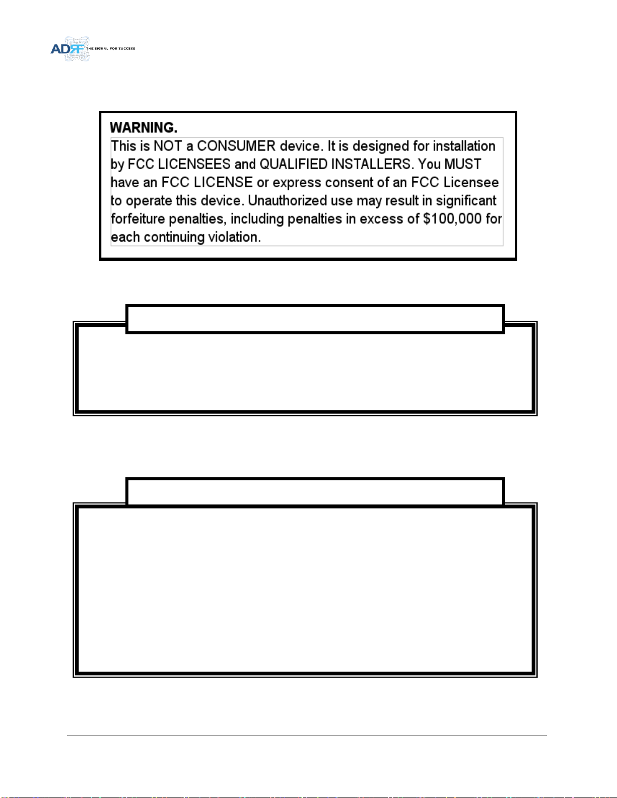
◈LABEL WARNING◈
FCC RF Radiation Exposure Statement:
This equipment complies with FCC RF radiation exposure limits set forth for an uncontrolled
environment. This equipment should be installed and operated with a minimum distance of
UL:35cm, DL:180 cm between the radiator and your body. This transmitter must not be co-located or
operating in conjunction with any other antenna or transmitter.
Regulatory Warning Statement
Under Industry Canada regulations, this radio transmitter may only operate using an antenna of a type and
maximum (or lesser) gain approved for the transmitter by Industry Canada. To reduce potential radio
interference to other users, the antenna type and its gain should be so chosen that the equivalent
isotropically radiated power (e.i.r.p.) is not more than that necessary for successful communication.
Conformément à la réglementation d’Industrie Canada, le présent émetteur radio peut fonctionneravec
une antenne d’un type et d’un gain maximal (ou inférieur) approuvé pour l’émetteur par Industrie Canada.
Dans le but de réduire les risques de brouillage radioélectrique à l’intention desautres utilisateurs, il faut
choisir le type d’antenne et son gain de sorte que la puissance isotroperayonnée quivalente (p.i.r.e.) ne
dépassepas l’intensité nécessaire à l’établissement d’une communication satisfaisante.
RSS-GEN, Sec. 7.1.2 –(transmitters)
Advanced RF Technologies, Inc.
15
This radio transmitter (identify the device by certification number, or model number if Category II)has
been approved by Industry Canada to operate with the antenna types listed below with the maximum
permissible gain and required antenna impedance for each antenna type indicated. Antenna types not
included in this list, having a gain greater than the maximum gain indicated for that type, are strictly
prohibited for use with this device.
Le présent émetteur radio (identifier le dispositif par son numéro de certification ou son numéro de
modèle s’il fait partie du matériel de catégorie I) a été approuvé par Industrie Canada pour fonctionner
avec les types d’antenne énumérés ci-dessous et ayant un gain admissible maximal et l’impédance requise
pour chaque type d’antenne. Les types d’antenne non inclus dans cette liste,ou dont le gain est supérieur
au gain maximal indiqué, sont strictement interdits pour l’exploitation de l’émetteur.
RSS-GEN, Sec. 7.1.2 –(detachable antennas)
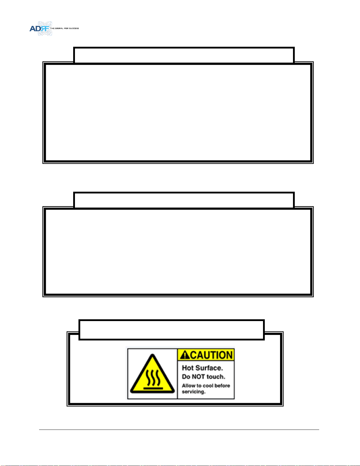
This equipment complies with RF radiation exposure limits set forth for an uncontrolled environment.
This equipment should be installed and operated with a minimum distance of UL: 35 cm, DL:180cm
between the radiator and your body. This transmitter must not be co-located or operating in conjunction
with any other antenna or transmitter. RF exposure will be addressed at time of installation and the use of
higher gain antennas require larger separation distances.
L’antenne (ou les antennes) doit être installée de façon à maintenir à tout instant une distance minimum
de au moins UL: 35 cm, DL:180cm entre la source de radiation (l’antenne) et toute personne physique.
Cet appareil ne doit pas être installé ou utilisé en conjonction avec une autre antenne ou émetteur.
RF Radiation Exposure
WARNING! Hot surface

Advanced RF Technologies, Inc.
16
2. OVERVIEW
2.1 LED
SDR-ICS-43-6 has an LED in the Lower left corner as shown in figure below.
Figure 2-1 LED
Table 2-1 RF Module LED Specifications
LED Indicator
Specifications
Service
Green
System is Normal
Orange
Soft Fail
Red
Hard Fail
2.2 Host/Remote Switch
Figure 2-2 Host/Remote Switch
The Host/Remote Switch allows the user to switch the default Repeater IP, Subnet Mask, and Gateway of the
LOCAL port of the repeater to an alternative setup. These settings can be adjusted by logging into the repeater in
HOST mode and configuring the settings under the Modem Box Setting section on the Install Page(section )
Once the settings are set, Push the switch to the REMOTE position will reboot the repeater with the new alternate
settings. Please note that when the repeater is set to the REMOTE position, DHCP is disabled and the repeater will
not automatically assign an IP address to any device that connects directly to the repeater.
Host IP: 192.168.63.1 (Fixed IP, unable to modify this IP address)
Remote IP: 192.168.63.5 (Default IP, but can be modified in Host mode)
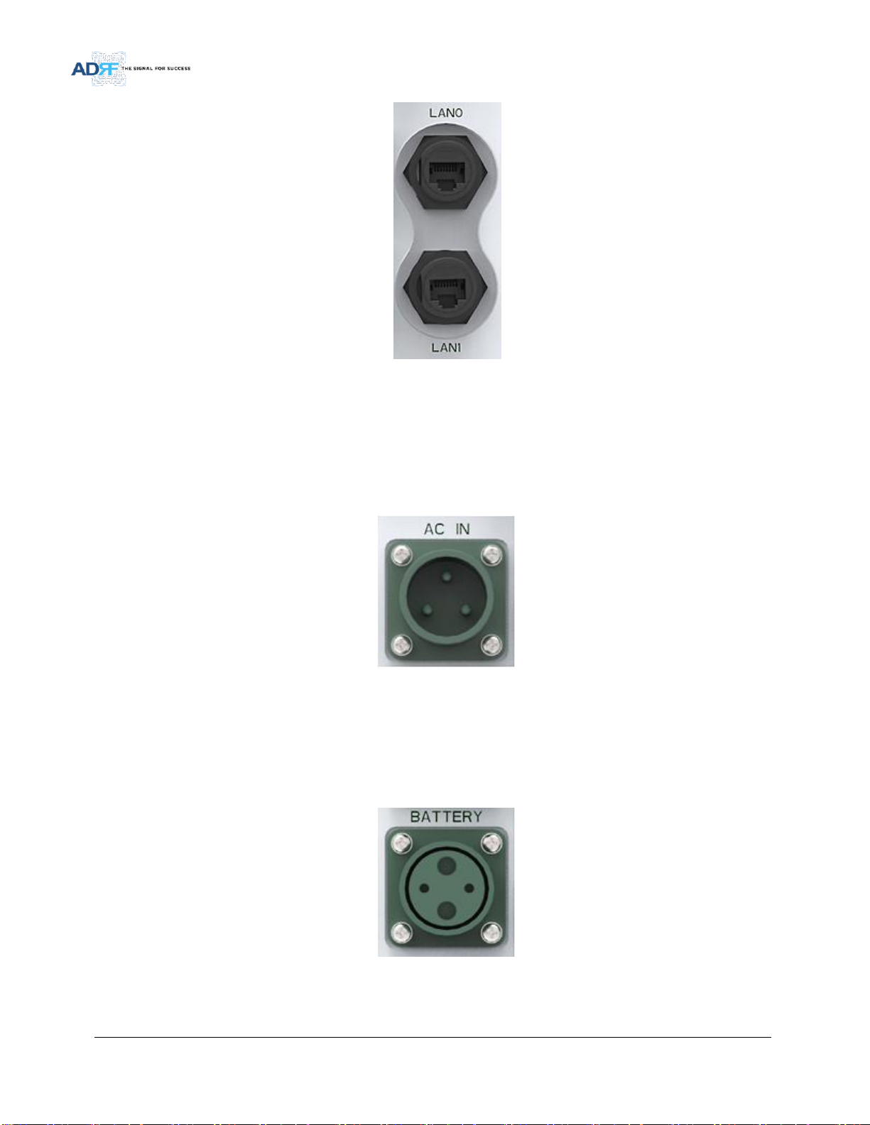
2.3 Ethernet Port
Advanced RF Technologies, Inc.
17
Figure 2-3 Ethernet Port
LAN0 –The Local port can be used to communicate directly with the SDR-ICS-43-6 using a RJ-45 crossover
cable or can also be used to connect the SDR-ICS-43-6 to an external modem box or the optional internal
Digi Transport WR-21.
LAN0 and LAN1 support cascade communication for modem and Web-GUI
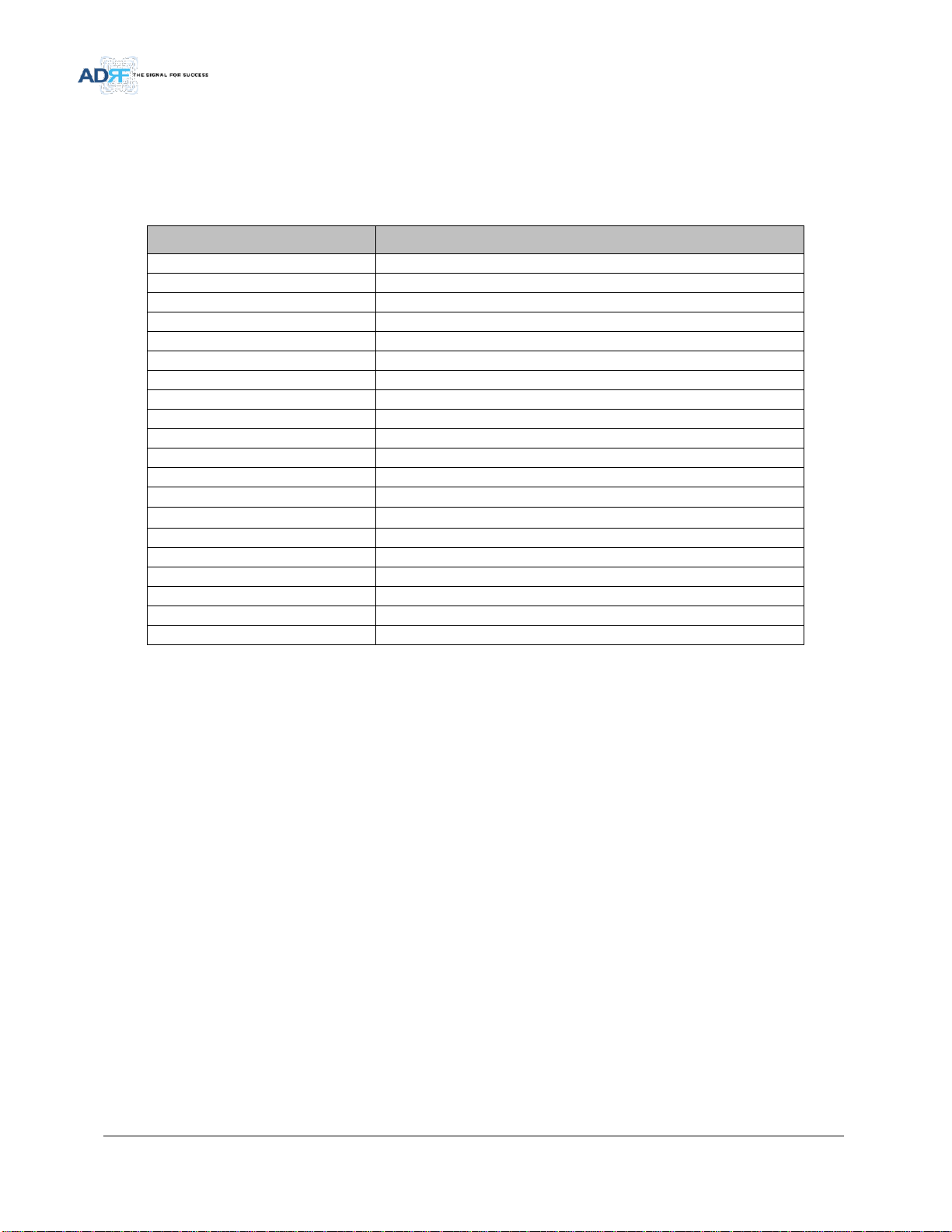
2.3.1 AC Power
Figure 2-3 AC Input Port
The SDR-ICS-43 PSU can operate at 110V AC to 220V AC. The user should verify that the AC input voltage is the
correct voltage before powering on the SDR-ICS-43.
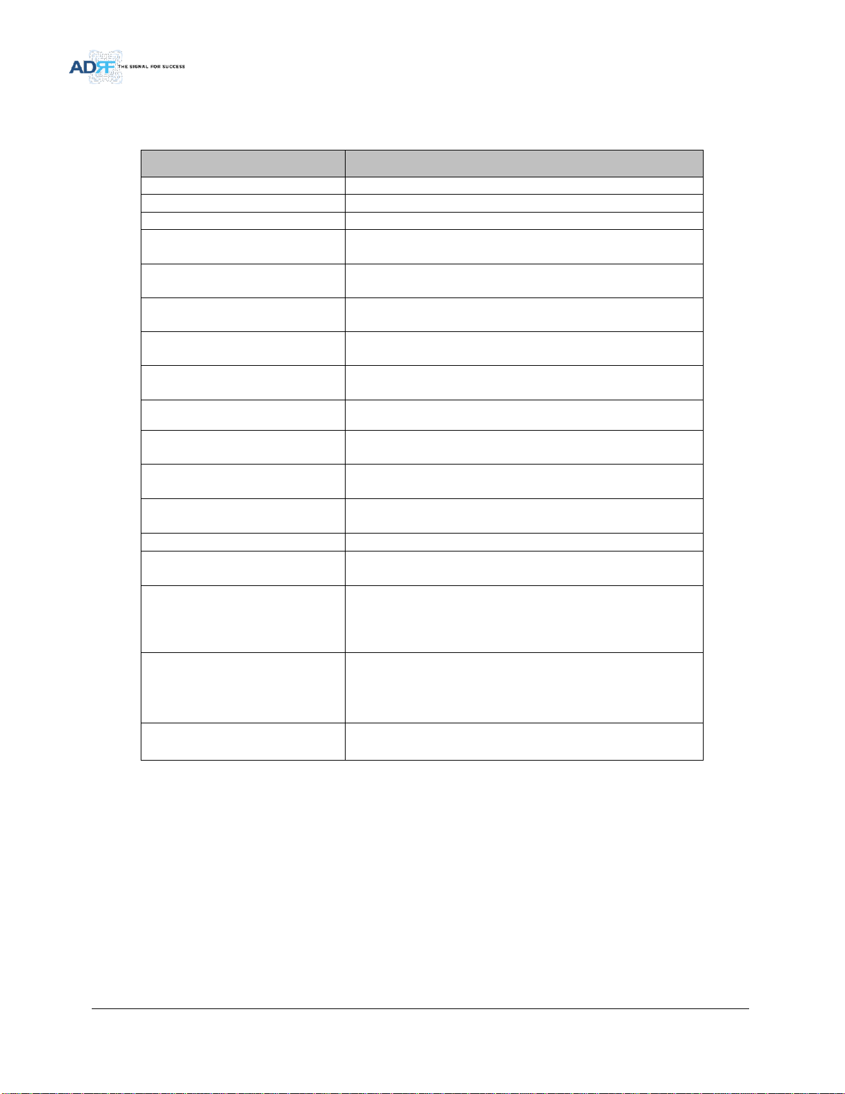
2.3.2 Back Up Battery Port
Figure 2-4 Battery Backup Port

Advanced RF Technologies, Inc.
18
The SDR-ICS-43-6 can be connected to an ADRF-BBU (ADRF Battery Backup) to provide power during a power
failure. If an ADRF-BBU is utilized, connect the ADRF-BBU to the SDR-ICS-43 via the external battery port.
(WARNING: The circuit switch on the ADRF-BBU must be set to OFF before connecting the ADRF-BBU to SDR-ICS-
43-6 to prevent damage to the repeater or the ADRF-BBU and personal injury.)
Note: Please contact ADRF Technical Support for assistance if you are unfamiliar with the installation procedure of
our battery box.
2.4 RF Ports
Figure 2-5 RF port
DONOR –4.3-10 female which is used to connect the donor antenna
DONOR_Modem CPL (20dB) –SMA female 20 dB coupling port which is used to Modem
MODEM_ANT –SMA female port which is used to provide RF signal to the optional external modem box or
connect the DONOR_ CPL port.
SERVER_CPL (30dB) –SMA female 30 dB coupling port which is used to monitor the amplified DL signal
SERVER –4.3-10 female which is used to connect the server antenna
DONOR
CPL(-20dB)
CPL(-40dB)
SERVICE
SERVER
LAN0
LAN1
BATTERY
AC IN
SDR-ICS-43-X
HOST
REMOTE
MODEM
ANT
SDR-ICS-43-6
Advanced RF Technologies, Inc.
19
3. ALARMS
3.1 Message Board Alarms and Notification
Table 3-1 Message Board Alarms and Notification
Parameters
Remark
AC Fail
Power supply is not operating within specs
DC Fail
Power supply is not operating within specs
Fan[1/2] Fail
System has detected an issue with the fan1 and fan2
Temperature
Module is above the normal operating temperature
Current
Power supply is not operating within specs
System Halt
System is in a shutdown state due to a hard fail alarm
DSP Fault
System has detected an issue with the internal DSP chip
OSC
Oscillation detected
DL Signal not detected
DL signal is below the specified level
DL Signal Low
DL signal is below the specified level
Input Overload
Incoming in-band DL or UL signal is too strong
Out of band Overload
Incoming out-band DL or UL signal is too strong
Synthesizer Lock Fail
Issue with internal PLL
DL RF Power
Input + gain does not match the output level (above delta of 6 dB)
Overpower
Output level is above the max output levels
VSWR
Power is being reflected back to the repeater
Heartbeat
Heartbeat
Reboot
Reboot
Factory setting
Factory setting
Sync Fail(SDR-ICS-43-BT only)
Sync Signal Not Detect, Sync Fail
Advanced RF Technologies, Inc.
20
3.2 Alarms
Table 3-2 Alarms Threshold
Parameters
Remark
AC Fail
Power supply is not operating within specs. (4 seconds)
DC Fail
Power supply is not operating within specs. (4 seconds)
Fan1, Fan2 Fail
System has detected an issue with each fan. (4 seconds)
Temperature
Module is above the normal operating temperature. (4 seconds)
Over Temperature [ Soft fail: 80~87 C, Hard fail: Above 87 C]
Current
Power supply is not operating within specs. (4 Second)
Over Current [ Hard fail: Above 20A]
System Halt
System is in a shutdown state due to a hard fail alarm. (10 times)
DSP Fault
System has detected an issue with the internal DSP chip. (Cannot
communication with DSP)
OSC
Oscillation detected. Alarm is only present when one-time
oscillation check is performed.
DL Signal not detected
DL signal is below the specified level. (default: -90dBm, 4 seconds)
DL Signal Low
DL signal is below the specified level. (default: -85dBm, 4 seconds)
Input Overload
Input signal is above the threshold. (4 seconds)
(Soft fail: DL -10dBm/UL -12dBm, Hard fail: DL -8dBm/UL -10dBm)
Out of band Overload
Out of band signal is above the threshold. (4 seconds)
(Soft fail: DL -10dBm/UL -12dBm, Hard fail: DL -8dBm/UL -10dBm)
Synthesizer Lock Fail
Issue with internal PLL(4 seconds)
DL RF Power
Input + gain does not match the output level
(default delta of 6 dB)
Overpower
Output level is above the max output levels
AGC On case(Soft: AGC Level+ 1~2dB, Hard: AGC Level + >2dB)
AGC Off case(Soft: max output level+ 1~2dB, Hard: max output
level + >2dB)
VSWR
Power is being reflected back to the repeater. Threshold = output
power - 8dB. For example, if the repeater is outputting 24dBm,
then if the system detects 16dBm of return power, then the VSWR
will be triggered.(Triggered in case of over +15dBm output power)
Sync(SDR-ICS-43-BT only)
Sync alarm set : Sync Fail
Sync alarm clear : Sync
Table of contents
Other ADRF Repeater manuals

ADRF
ADRF Duo-i6525 User manual

ADRF
ADRF Duo-i6525 User manual

ADRF
ADRF PSR-VU-9537-UB User manual

ADRF
ADRF Epoch-III-P8024 User manual

ADRF
ADRF SDRX-43-BTF User manual

ADRF
ADRF SDR-ICS-43 User manual

ADRF
ADRF SDR-ICS-43-W User manual

ADRF
ADRF Duo-i6515NM User manual

ADRF
ADRF PSR78 User manual

ADRF
ADRF FiRe-78-4 User manual


