ADS Sentry User manual
[Sentry Trailer – Operation, Startup, and Shutdown Procedures]
Sentry Trailer
Operation, Startup, and Shutdown Procedures
Safety Warnings
CAUTION
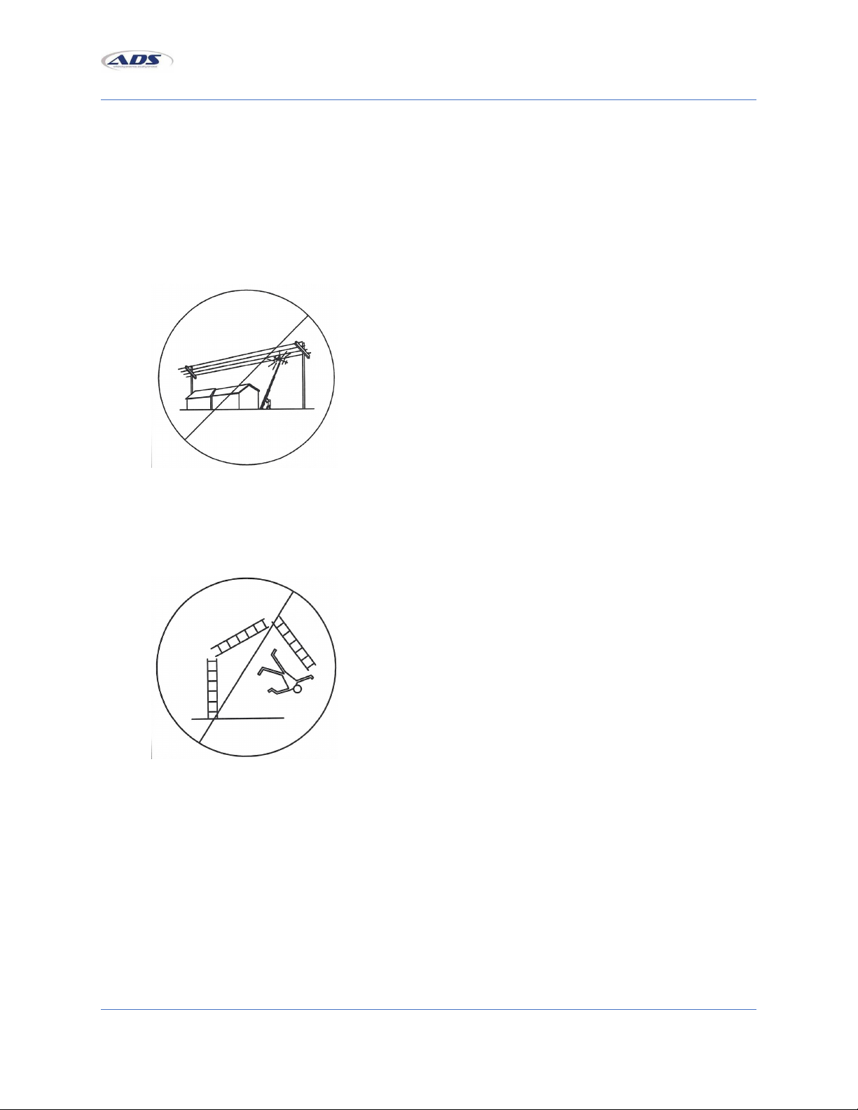
Never set up the tower within 120 feet of a power line.
Never erect the tower during an electrical storm, rainstorm, or when lightning is a possibility.
Never climb the tower for any reason. Always lower the tower completely and access it with a
suitable ladder or platform.
Never overextend the tower height. When at maximum height, the orange rung on the second
tower section from the bottom) rests on the orange safety stop at the top of the base tower
section).
Always tow the trailer in a level position to meet height restrictions. Adjust coupler height as
needed.
1

[Sentry Trailer – Operation, Startup, and Shutdown Procedures]
Always make sure your tow vehicle and hitch capacity are suitable for the trailer you are towing.
These items must be rated according to the GVWR on the V.I.N. decal on the front of your trailer
tower unit.
Always evenly distribute your load to maintain safe handling conditions when towing your trailer
tower unit.
Always maintain the proper tire pressure according to the specification decal located on the
front of your trailer tower unit.
Never tow the trailer with the outrigger jacks in place. Remove them and stow on rear frame, or
in a storage box.
Before transporting the trailer/tower, make sure that the tower hold-down cable and the "Red
Strap" at the rear bottom end of the tower are in place and secure.
When transporting trailer and tower, drive within the speed limits and do not exceed 55MPH.
Always following basic ladder safety guidelines when using the trailer tower accessory ladder s):
oInspect the ladder before each use to verify that it is in satisfactory condition. Never
climb a damaged ladder.
oAlways set up the ladder on a firm, level surface where no slipper conditions are
present, either at the base, or at the top support points.
oOnly one person at a time should climb a ladder.
2

[Sentry Trailer – Operation, Startup, and Shutdown Procedures]
oRead the safety information labels on the ladder. No person is considered qualified to
climb a ladder until he/she is familiar with the information that is specific to that type of
ladder.
oDo not leave tools or materials resting on any rung, step, or platform of an unattended
ladder.
oWhen working in windy conditions do not leave an upright ladder unattended.
Always wear a hard hat and a pair of durable work gloves when deploying the unit or breaking it
down.
When wet, damp, or slick conditions are present, exercise extreme caution when climbing or
maneuvering on the trailer deck or shelter.
Trailer Tower Setup Instructions with Guy Wires
Safety Warnings
CAUTION
NE ER setup the tower within 120 feet of a power line.
NE ER attempt to climb your tower under any circumstances. Always lower tower completely
and access your tower by use of a suitable ladder. The rungs cannot support the weight of a
person.
ALWAYS tow the trailer in a level position to meet height restrictions. Adjust coupler height as
needed.
ALWAYS make sure your tow vehicle and hitch capacity are suitable for the trailer you are
towing. These items must be rated according to the GVWR on the V.I.N. decal on the front of
your trailer tower unit.
NE ER overload your trailer or the tongue of your trailer. The GVWR noted on your V.I.N. decal
is the maximum loaded weight of your trailer tower unit.
ALWAYS evenly distribute your load to maintain safe handling conditions when towing your
trailer tower unit see “Weight Distribution” notice)
ALWAYS maintain the proper tire pressure according to the specification decal located on the
front of your trailer tower unit
NE ER tow the trailer with the outrigger jacks in place. Remove them and stow on rear frame or
in storage box.
BEFORE transporting trailer/tower check to see that both, the tower hold-down cable and the
“Red Strap” at the rear bottom end of the tower are in place and secure.
WHEN transporting trailer and tower, drive within the speed limits and do not exceed 55MPH.
3

[Sentry Trailer – Operation, Startup, and Shutdown Procedures]
Getting Ready to Transport
1. After hooking up the trailer to the tow vehicle, fully retract the front tongue jack and lock it into
the travel position see Fig. 1A or 1B).
2. Attach the hooks on the safety chains to the tow vehicle frame. Be sure to cross the chains
under the coupler and leave enough slack for turning see Fig.2).
3. Hook up the trailer lights by plugging the connector into the receptacle on the tow vehicle.
Check all lights Brake, Stop, and Running) to see that they are functioning properly.
If using electric brakes, check to see that they are properly connected and that the brake
controller is in proper working order.
4. Next, hook up the small wire cable that operates the breakaway brake control see Fig. 3).
Positioning the Trailer/Tower
1. Position the unit in a place that will allow the following radius around the tower:70 foot radius
for the T-100H & T-100UGH towers; 60 foot radius for T-85UGH tower; 55 foot radius for the T-
75H tower; and a 40 foot radius for the T-50H tower.
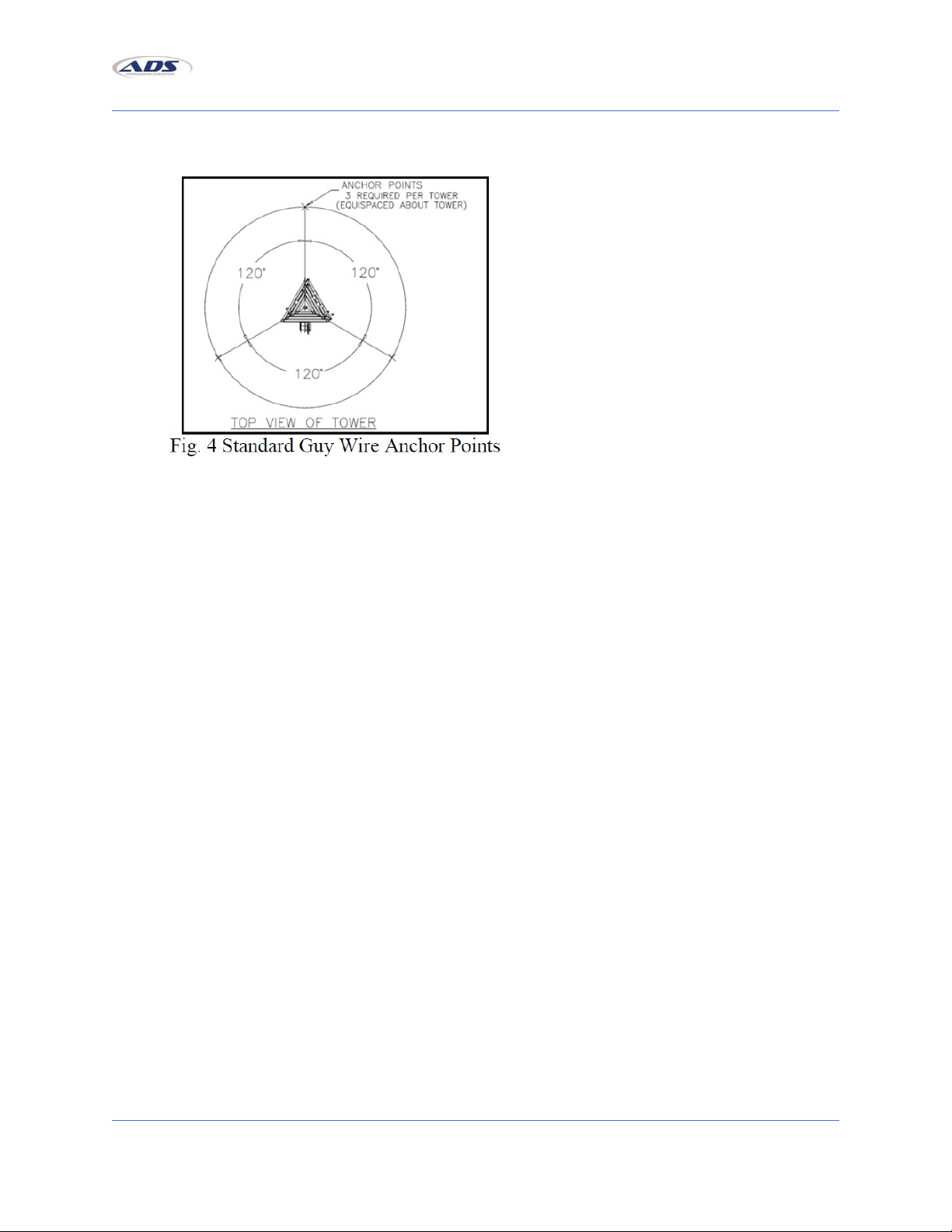
2. Mark the location 120 degrees apart) of each anchor point see Fig. 4). Refer to the enclosed
appropriate guy wire drawing specifications for your specific model.
4
[Sentry Trailer – Operation, Startup, and Shutdown Procedures]
As an alternate, the Model GA-1 or GA-2 helical screw type guy anchors or CGA-1680 concrete
type ground anchors can be used.
3. The tow vehicle must now be uncoupled from the unit.
a. Remove the safety pin and unlatch the coupler. Either swivel and lock the front tongue
jack into the useable position and crank it down so the tow vehicle can be moved away
see Fig. 1A) OR pull the pin on the dropleg jack and allow the leg to drop to its lowest
position.
b. Realign the through holes and reinsert the pin. Crank it down so the tow vehicle can be
moved away see Fig. 1B).
c. Disconnect the safety chains, light connector cable, and breakaway cable from the tow
vehicle.
4. Remove the two hitch pins that hold the rear “outriggers” in the stowed position.
a. Carefully pull them out until the second set of pinholes is visible.
b. Then, reinsert the pins with the outriggers in the extended position see Fig. 5).
c. Repeat for the front “outriggers”.
5

[Sentry Trailer – Operation, Startup, and Shutdown Procedures]
5. Remove jacks from storage box and install two jacks on the front outriggers and two jacks on the
rear outriggers of the trailer.
6. Level the trailer by using the four jacks and the bubble levels as a guide.
On models that include a shelter, the bubble level is located on the rear corner of the shelter
and for units without a shelter, the bubble level is located on the rear upright tower support).
Attaching the Antenna, Coax Ca le, and Guy Wires
1. Remove the thru bolts from the upper and lower mast adaptor plates.
a. Insert the mast through the upper plate mast adaptor.
b. Slide the mast into the lower plate mast adaptor until it is fully seated against plate.
c. Turn the mast to align the bolt thru holes.
d. Reinsert the bolts and fully tighten the nuts.
2. Feed the coax cable through the middle of the smallest section and up through the mast at the
top of the tower.
3. Mount the antenna to the mast per the manufacturer’s specifications and connect the coax.
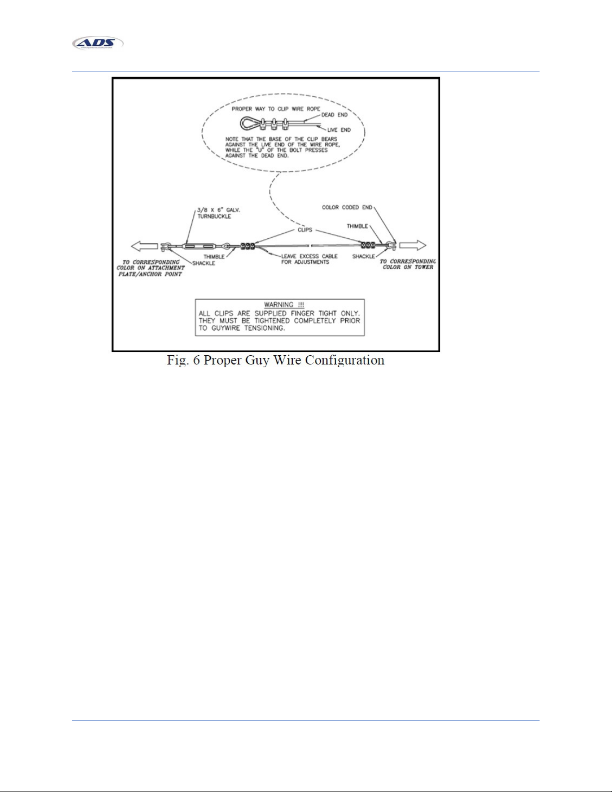
4. Attach the color-coded ends of the guy wires to the corresponding color-coded guy ears at the
top of each section of the tower, using the screw pin shackle see Fig. 6). Be sure to tighten the
screw pin shackle with a wrench.
a. Lay the appropriate sets of three each guy wires in the general direction to which they
will be anchored. see Fig. 4).
b. See below if “Erecting the Tower at Less Than Full Height”.
6
[Sentry Trailer – Operation, Startup, and Shutdown Procedures]
5. IMPORTANT! Check winch cable and make sure the cable is properly seated on each pulley
sheave.
a. Using the winch, apply tension to the winch cable BEFORE tilting to the vertical position.
This will keep the cable properly seated on the sheave and keep the pulleys from being
damaged.
Erecting the Tower at Full Height
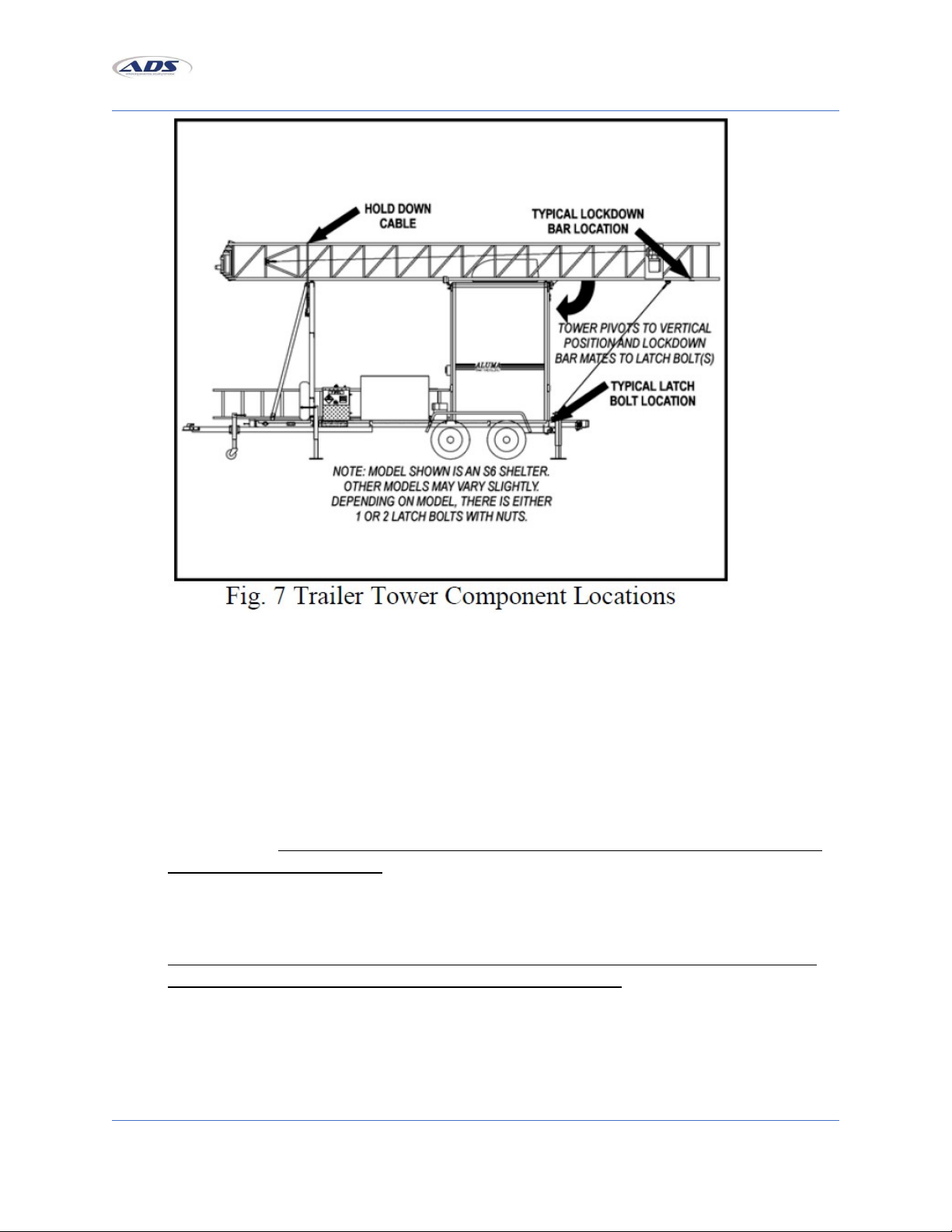
1. While the tower is still in the horizontal position, loosen and remove the hold down restraining
cables that hold the tower in place for transporting. These cables are located on the front
support of the trailer and/or shelter see Fig. 7).
7
[Sentry Trailer – Operation, Startup, and Shutdown Procedures]
NOTE: There may be more than one hold down cable at varying locations, depending on your
specific model.
2. Using the manual brake winch on the rear support, crank the tower from the horizontal to the
vertical position.
a. At the halfway position, undo the nut s) from the latch bolt s) at the bottom rear of the
trailer frame see Fig. 7).
NOTE: Sufficient load must be applied to the cable to overcome internal resistance and operate
brake properly. NEVER CONTINUE TURNING THE HAND E COUNTER-C OCKWISE IF THE CAB E
DOES NOT KEEP MOVING OUT. This will disengage the brake mechanism and create an unsafe or
hazardous condition.
MINIMUM OPERATING LOAD REQUIREMENTS - MODEL 5351 - 75 lbs.
Failure to read and apply the instructions and warnings contained in this manual can result in
sudden failure of equipment, property damage and serious injury.
3. Secure the tower in the vertical position with the tower lockdown bar pivoting over the latch
bolt s) on bottom of rear trailer frame see Fig. 7).
8

[Sentry Trailer – Operation, Startup, and Shutdown Procedures]
a. Tighten the nut s) with wrenches supplied in tool kit TM-TK, which is stored in the #664
or #684 storage box.
b. Drive all three “Duckbill Ground Anchors” into the ground as described in the attached
instructions, AT-418-1.
4. Take the loose end of the three lowest guy wires and attach them to the ground anchors.
Tighten only the lowest set of guy wires. The turnbuckles should be adjusted to the fully
extended position for maximum adjustment.
a. Recheck the bubble levels to be sure the trailer is still level.
b. Also, use the 4-foot level to further check to see that the tower is as level and plumb as
possible. If tower is not level, readjust the jacks on the trailer to re-level trailer.
5. IMPORTANT: Undo the Red Safety strap from the bottom of the tower and remove it from the
inner sections. It is necessary for this strap to be removed. The power winch raising the tower
can damage the tower if this strap is not removed. Please note that this strap is used to keep the
tower from telescoping out on its own when in the transport mode. Additionally, you should pull
the orange safety stop release cord to ensure the safety stop releases properly before raising
the tower.
CAUTION! Do not attempt to raise tower in winds over 10 mph. Even in winds between calm
and 10 mph there MUST BE a person at each of the guy wires to ensure that the wires are kept
taut.
6. Raise the tower to the desired height. The safety stop engages at a rung approximately every 20
inches.
Remember that the electric winch is capable of damaging the tower, so be alert to any unusual
noises or signs that may indicate that you are doing damage to the tower. Do not try to
overextend the tower.
The tower is fully extended when the black and orange tape bands on the vertical legs of the
outer section are aligned with the bands on the inner section. When at maximum height, the
rung marked with orange reflective tape is just above the safety stop mechanism, allowing the
safety stop to rotate under this rung. The safety stop is located at the top of the lowest section.
Allow the tower to lower until the inner section rung, marked with orange reflective tape, rests
on the safety stop. Winch cable will slacken when this occurs. Serious damage will occur if
overextended!
7. Snug the remaining guy wires by starting at the lowest set. Be careful in tightening the wire and
check to be sure the tower remains aligned and level. The lowest set of guy wires can be
tightened securely; the remaining sets should only be snugged loosely.
THE TOWER IS NOW READY FOR USE.
9

[Sentry Trailer – Operation, Startup, and Shutdown Procedures]
Erecting the Tower at Less than Full Height
In some instances, erecting the tower at less than full height may be adequate for communications.
NOTE: All color-coded guy wires WILL NOT be attached to the corresponding color-coded guy ears when
using this method.
1. Attach the blue color-coded ends of the guy wires to the corresponding blue color-coded guy
ears at the top of the bottom section of the tower. Attach the yellow color-coded ends of the
guy wires to the red color-coded guy ears at the top of the top section of the tower, using the
screw pin shackle see Fig. 6). Be sure to tighten the screw pin shackle with a wrench. Lay the
appropriate sets of three each guy wires in the general direction to which they will be anchored.
DO NOT attach guy wires to the middle section of the tower).
2. Continue with directions “Erecting the Tower at Full Height” with one exception; stop raising the
tower when the top guy wires become taut. Do not overextend the tower.
Lowering the Tower
1. Slacken all guy wires except the lowest set.
a. Crank the tower up slightly to allow the safety stop to swing out of the way. The safety
stop is controlled by an orange cord attached to one leg of the tower.
b. After the tower has been cranked up slightly, pull the orange cord until the safety stop
clears the rung above it.
c. Start lowering the tower while keeping tension on the orange cord. The safety stop
must be kept out of the way for the complete lowering of the tower.
2. After the tower has been lowered to the retracted position, be sure to reattach the “Red Safety
Strap” around the inner section s).
3. Remove guy wires from anchors while still in vertical position.
4. Remove the nut from the latch bolt on tower lockdown bar.
a. Be sure to retighten the nut with a wrench so that it will not vibrate loose while
transporting.
b. Push the tower away from the trailer while playing out the cable from the winch.
NOTE: Sufficient load must be applied to the cable to overcome internal resistance and operate
brake properly. NEVER CONTINUE TURNING THE HANDLE COUNTERCLOCKWISE IF THE CABLE
DOES NOT KEEP MOVING OUT. This will disengage the brake mechanism and create an unsafe or
hazardous condition.
MINIMUM OPERATING LOAD REQUIREMENTS - Model 5351 - 75 lbs.
Failure to read and apply the instructions and warnings contained in this manual can result in
sudden failure of equipment, property damage and serious injury.
5. Lower the tower to the horizontal position and secure the tower with the hold down cable.
10
Table of contents


