Thern 5FT40 Series User manual

A27607-A-1120
Thern
Winches &Cranes
Read this Owner’s Manual
thoroughly before operating
the equipment. Keep it with
the equipment at all times.
Replacements are available
from Thern, Inc., PO Box 347,
Winona, MN 55987,
507-454-2996.
www.thern.com
IMPORTANT: Please record
product information on
page 2. This information is
required when calling the
factory for service.
ORIGINAL TEXT
Owner’s Manual
For
5FT40 Series Stationary Davit Cranes

A27607-A-1120
page 2
Owner's Manual for Thern 5FT40 Captain Series Stationary Davit Cranes
Please record the following:
Date Purchased:
Crane Model No.:
Crane Serial No.:
If sold with a winch:
Winch Model No.:
Winch Serial No.:
This information is required when
calling the factory for service.
Two-Year Limited Warranty
Thern, Inc. warrants its products against defects in material or workmanship for two years from the date of purchase
by the original using buyer, or if this date cannot be established, the date the product was sold by Thern, Inc. to the
dealer. To make a claim under this warranty, contact the factory for an RGA number. The product must be returned,
prepaid, directly to Thern, Inc., 5712 Industrial Park Road, Winona, Minnesota 55987. The following information
must accompany the product: the RGA number, the date of purchase, the description of the claimed defect, and a
complete explanation of the circumstances involved. If the product is found to be defective, it will be repaired or
replaced free of charge, and Thern, Inc. will reimburse the shipping cost within the contiguous USA.
This warranty does not cover any damage due to accident, misuse, abuse, or negligence. Any alteration, repair or
modification of the product outside the Thern, Inc. factory shall void this warranty. This warranty does not cover any
costs for removal of our product, downtime, or any other incidental or consequential costs or damages resulting from
the claimed defects. This warranty does not cover brake discs, wire rope or other wear components, as their life is
subject to use conditions which vary between applications.
FACTORY AUTHORIZED REPAIR OR REPLACEMENT AS PROVIDED UNDER THIS WARRANTY IS THE
EXCLUSIVE REMEDY TO THE CONSUMER. THERN, INC. SHALL NOT BE LIABLE FOR ANY
INCIDENTAL OR CONSEQUENTIAL DAMAGES FOR BREACH OF ANY EXPRESS OR IMPLIED
WARRANTY ON THIS PRODUCT. EXCEPT TO THE EXTENT PROHIBITED BY APPLICABLE LAW, ANY
IMPLIED WARRANTY OF MERCHANTABILITY OR FITNESS FOR A PARTICULAR PURPOSE ON THIS
PRODUCT IS LIMITED IN DURATION TO THE DURATION OF THIS WARRANTY.
Some states do not allow the exclusion or limitation of incidental or consequential damages, or allow limitations on how
long an implied warranty lasts, so the above limitation or exclusion may not apply to you. This warranty gives you
specific legal rights, and you may also have other rights which vary from state to state.
Note: Thern, Inc. reserves the right to change the design or discontinue the production of any product without
prior notice.
About This Manual
The Occupational Safety and Health Act of 1970 states that it is the employer’s
responsibility to provide a workplace free of hazard. To this end, all equipment
should be installed, operated, and maintained in compliance with applicable trade,
industrial, federal, state, and local regulations. It is the equipment owner's
responsibility to obtain copies of these regulations and to determine the suitability
of the equipment to its intended use.
This Owner’s Manual, and warning labels attached to the equipment, are to serve
as guidelines for hazard-free installation, operation, and maintenance. They should
not be understood to prepare you for every possible situation.
Theinformationcontained inthis manualis applicableonlytothe Thern Captain
Series Model 5FT40 Stationary Davit Cranes. Do not use this manual as a source
of information for any other equipment.
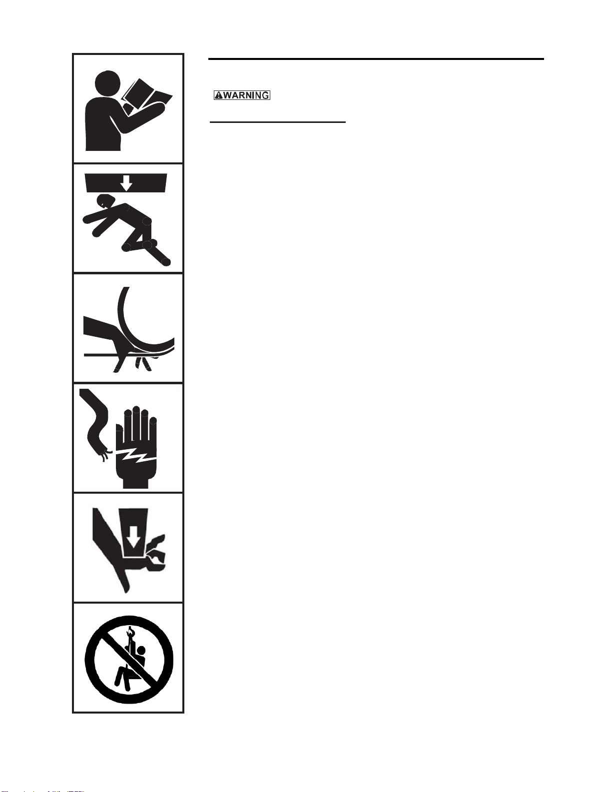
The following symbols are used for emphasis throughout this manual:
Failure to follow ‘WARNING!’ instructions may result in equipment damage,
property damage, and/or serious personal injury.
Failure to follow ‘CAUTION!’ instructions may result in equipment damage,
property damage, and/or minor personal injury.
Important!
Failure to follow ‘important!’ instructions may result in poor performance of
the equipment.

A27607-A-1120
Owner's Manual for Thern 5FT40 Captain Series Stationary Davit Cranes
page 3
Suggestions for Safe Operation
DO the following:
Read and comply with the guidelines set forth in this Owner’s Manual. Keep
this manual, and all labels attached to the crane, readable and with the
equipment at all times. Contact Thern, Inc. for replacements.
Check lubrication before use.
Check for leaks before use.
Install the wire rope securely to the winch drum.
Keep at least 4 wraps of wire rope wound on the drum at all times, to serve as
anchor wraps. With less than 4 wraps on the drum the wire rope could come
loose, causing the load to escape.
Keep hands away from sheaves, gears, wire rope, and other moving parts.
Disconnect any power before servicing the equipment.
Keep all unnecessary personnel away from crane while in operation.
Keep out of the path of the load, and out of the path of a broken wire rope
that might snap back and cause injury.
Ensure that both threaded ends of the ratchet jack are threaded an equal
distance out of the jack when assembled to the crane. If threaded ends are not
equal, the crane boom will not be able to operate in its full range of motion.

A27607-A-1120
page 4
Owner's Manual for Thern 5FT40 Captain Series Stationary Davit Cranes
Suggestions for Safe Operation (cont.)
DO NOT do the following:
Do not lift people, or things over people. Do not walk or work under a load
or in the line of force of any load.
Do not exceed the load rating of the crane or any other component in the
system. To do so could result in failure of the equipment.
Do not use more than one crane to move a load that exceeds the load rating
of a single crane. A shift in load weight could overload the equipment.
Do not use damaged or malfunctioning equipment. To do so could result in
failure of the equipment.
Do not modify the equipment in any way. To do so could cause equipment
failure.
Do not wrap the wire rope around the load. This damages the wire rope and
could cause the load to escape. Use a sling or other approved lifting device.
Do not operate the crane with guards removed or improperly installed.
Do not divert your attention from the operation. Stay alert to the possibility
of accidents, and try to prevent them from happening.
Do not jerk or swing the load. Avoid shock loads by starting and stopping
the load smoothly. Shock loads overload the equipment and may cause
damage.
Do not use the crane and winch components for any use other than for their
original intended function.
Do not use the crane to drag or pull loads. This will create side pulls, which
could damage the equipment or cause the load to tip.
Do not leave a suspended load unattended. Place the load on the ground if it
must be left unattended.
Do not adjust the winch brake with the load suspended.
Do not operate or apply loads without all pins securely in place.
Do not adjust the boom extension while the crane is loaded.
Do not make adjustments to the ratchet jack while the crane is loaded. Todo
so may require the use of excessive force which could cause damage or injury.

A27607-A-1120
Owner's Manual for Thern 5FT40 Captain Series Stationary Davit Cranes
page 5
1.1 Installing the Crane
Do not install the crane in an area defined as hazardous by the National Electric
Code, unless installation in such an area has been thoroughly approved.
Do not install the crane near corrosive chemicals, flammable materials,
explosives, or other elements that may damage the crane or injure the operator.
Adequately protect the crane and the operator from such elements.
Position the crane so the operator can stand clear of the load, and out of the path
of a broken wire rope that could snap back and cause injury.
Attach the crane to a rigid and level foundation that will support the crane and
its load under all load conditions, including shock loading.
1.1.1 CONSULT APPLICABLE CODESAND REGULATIONS for specific
rules on installing the equipment.
1.1.2 LOCATE THE CRANE in an area clear of traffic and obstacles that could
interfere with operation. Make sure the crane is accessible for maintenance
and operation.
1.1.3 INSTALL THE CRANE on a level surface.
1.1.4 FASTEN THE BASE securely to the foundation to withstand applicable
overturning moments and mounting bolt reaction. See Table 1.
a FOR STANDARD PRODUCTS referred to in this manual, use coarse
thread fasteners, grade 5 or better.
Suggested Fastener Torque Values (ft-lbs)
Plain & Dry
Zinc Plated
Lubricated
(eg. Loctite)
3/4 inch grade 5
260
230
200
M20 grade 8.8
320
270
240
Refer to manufacturer's instructions for other fastener types with
specific torque or installation instructions.
b NON-STANDARD PRODUCTS that vary from the original design may
have different fastening requirements. Contact a structural engineer or
Thern, Inc. for this information.
TO COMPLY WITH LOCAL CODES, CONTACT A QUALIFIED
PROFESSIONAL TO OBTAIN PROPER STRUCTURE OR FOUNDATION
SPECIFICATIONS FOR THE MOUNTING OF THERN PRODUCTS.
Table 1 –Crane Reactions
Crane
Model
Mast
Moment
Suggested
Bolt Size
Force per
Bolt (tension)
5FT40
398,100 in-lbs
44,982 N-m
3/4 inch (M20)
6,470 lbs
28,782 N
This information may change without prior notice. It is the responsibility of the installer and/or
end user to ensure the most current information is used.
Important!
•
A qualified professional
should inspect or design the
foundation to insure that it
will provide adequate support.
•
Locate the crane so it will be
visible during the entire
operation.

A27607-A-1120
page 6
Owner's Manual for Thern 5FT40 Captain Series Stationary Davit Cranes
Figure 1 –Cotter Pins
1.2 Assembling the Crane
When installing the support jack, support the end of the boom so the boom does
not fall and the support jack does not swing causing damage or injury.
When installing the boom extension, hold the boom extension securely so it does
not slide abruptly in or out of the boom causing damage or injury.
1.2.1 STUDY PARTSDRAWINGS to understand how the crane is assembled.
See pages 19-20.
1.2.2 LUBRICATE THE ENTIRE CRANE as you assemble it. Refer to the
Lubrication Instructions in Section3.2
1.2.3 INSTALL THE BASE. See Section 1.1 for additional information and crane
overturning moments and mounting bolt reaction forces.
1.2.4 INSTALL THE SUPPORT JACK, ratchet style or hydraulic (if equipped).
a ENSURE THAT BOTH THREADED ENDS of the ratchet jack are anequal
distance out ofthe jack whenassembled to the crane. If threaded ends are not
equal, the crane boomwill not be able to operate in its full range of motion.
b FASTEN ONE END OF THE SUPPORT JACK to the mountingearon the
mast with clevis and cotter pin provided. See Figure 1.
1.2.5 FASTEN THE BOOM to the mast using the clevis and cotter pin provided.
For manual winch models, install a sheave on the boom pin as you
fasten the boom to the mast.
1.2.6 POSITION THE BOOM carefully so the other end of the support jack aligns
with the mounting ear and secure using the clevis and cotter pin provided.
1.2.7 ADJUST THE BOOM with the support jack so the boom is horizontal.
1.2.8 SLIDE THE BOOM EXTENSION into the boom, and secure in place with the
clevis pin and cotter pin provided. Make sure the boom extension is
positioned correctly withauxiliary mounting holestowardthe ground.
1.2.9 FASTEN THE WINCH to the appropriate mounting plate. Manual winches
should be installed on the mast. Power winches should mount on the boom.
1.2.10 INSTALL THE WINCH HANDLE on hand winches, or connect electric
current on power winches. Refer to instructions in the Winch Owner’s Manual.
1.2.11 INSTALL THE WIRE ROPE.
a REMOVE ROPE KEEPER PIN at the sheave to allow rope to be installed.
b PASS THE WIRE ROPE over the sheave and reinstall rope keeper pin to
prevent the rope from escaping the sheave rope groove.
d ANCHOR THE WIRE ROPE to the winch drum and wind 4 wraps ofwire
rope onto the drum to act as anchor wraps. Refer to the instructions in the
Winch Owner’s Manual.
1.2.12 MAKE SURE ALL FASTENERS are tightened with all clevis and cotter
pins in place to prevent components from shifting during use.
1.2.13 INSTALL UPPER TRAVEL LIMIT SWITCH when supplied with power
winchesasdirectedinsupplementalinstructionsprovidedwithlimit switch.
Important!
•Inspect the crane during
assembly according to the
Instructions for Periodic
Inspection. This will give
you a record of the condition
of the crane with which to
compare future inspections.
•Save all boxes and crates
that the crane was shipped
in, use them again if you
need to repackage the crane.
•Contact the factory
immediately ifany parts are
missing or damaged.
•Do not overtighten
fasteners, this may strip
threads or cause damage
to other parts.

A27607-A-1120
Owner's Manual for Thern 5FT40 Captain Series Stationary Davit Cranes
page 7
2.1 General Theory of Operation
2.1.1 THE INTENDED USE of this machinery is to lift and lower loads of its
rated capacity or less. It is not for lifting people or things over people.
2.1.2 THE FORCE REQUIRED to lift the load must not exceed the load rating
of the crane. Consider the total force required to lift the load, not the weight
of the load.
2.1.3 THIS EQUIPMENT CAN develop forces that will exceed the load rating.
It is the responsibility of the equipment user to limit the size of the load.
Inspect the equipment regularly for damage according to the instructions
contained in this manual.
2.1.4 PERFORMANCE RATINGS of the equipment are affected by the
position of the boom, and the amount of wire rope you use. Crane load
ratings decrease as you extend the reach.See the Performance
Characteristics Tables on page 22.
a LOAD RATING represents the maximum force that can be placed on new
equipment. Load ratings are assigned values for specific boom positions
and wire rope lengths.
b LIFT varies with the position of the boom, the length of the wire rope.
c REACH varies with the position of the boom.
2.1.5 DUTY RATINGS refer to the type of use the equipment is subject to.
Consider the following when determining duty rating.
a ENVIRONMENT: harsh environments include hot, cold, dirty, wet,
corrosive, or explosive surroundings. Protect the equipment fromharsh
environments when possible. Operating temperature range with manual
winches is -40ºF to +122ºF. Operating temperature range for standard
power winches is -4ºF to 104ºF.
b MAINTENANCE: poor maintenance, meaning poor cleaning,
lubrication, or inspection, leads to poor operation and possible damage of
the equipment. Minimize poor maintenance by carefully following the
instructions contained in this manual.
C LOADING: severe loading includes shock loading and lifting loads that
exceed the load rating of the equipment. Avoid shock loads, and do not
exceed the load rating of the equipment.
d FREQUENCY OF OPERATION: frequent or lengthy operations increase
wear and shorten the life span of gears, bearings, sheaves, and other
components. Increase maintenance of the equipment if used in
frequent operations.
2.1.6 AIRBORNE NOISE EMISSIONS vary depending on load and the type of
winch being used. Standard configurations do not typically exceed a sound
pressure level of 80 dB(A) at workstations.
2.1.7 VIBRATION LEVELS vary depending on load and type of winch being used.
Standard configurations do not typically exceed vibration levels of 2.5 m/s2.
CONTACT THE FACTORY FOR MORE INFORMATION.
Important!
•Limit non-uniform winding
by keeping tension on the
wire rope.
•It is your responsibility to
detect and account for
different factors affecting the
condition and performance
of the equipment.

A27607-A-1120
page 8
Owner's Manual for Thern 5FT40 Captain Series Stationary Davit Cranes
2.2 Preparing for Operation
Do not make adjustments to the ratchet jack while the crane is loaded. Todo so
may require the use of excessive force which could cause damage or injury.
Do not adjust the boom extension while the crane is loaded.
When adjusting boom length, set the boom angle just above the lowest angle
and hold the boom extension securely so it does not slide abruptly in or out of
the boom causing damage or injury.
2.2.1 CONSIDER THE OPERATION. Do not begin until you are sure you can
perform the entire operation without hazard.
2.2.2 INSPECT ALL COMPONENTS of thesystem.
a INSPECT THE CRANE and other equipment according to the Instructions
for Frequent Inspection.
b INSPECT THE WINCH according to the instructions in the WinchOwner’s
Manual.
c OPERATORS must be in good health, alert, thoroughly trained in operating
the equipment, and properly clothed (hard hat, safety shoes and safety
glasses, no loose clothing).
d THE LOAD must be clear of other objects and free to move. Make sure the
load will not tip, spin, roll away, or in any way move uncontrollably.
2.2.3 KNOW YOUR LOAD and make sure you do not exceed the load rating of
the crane or any other equipment in the system.
2.2.4 POSITION THE BOOM so the load hook is centered over the load. Avoid
side pulls which could damage the crane or cause the load to tip. See
Figure 2.
a ADJUST BOOM LENGTH by moving the boom extension in or out. Do
not make adjustments while the crane is loaded. The load rating
decreases as you increase boom length. See the Performance
Characteristics Tables on page 22.
b ADJUST BOOM ANGLE by operating the support jack to raise or lower
the boom between horizontal and 45 degrees. The lift height below base
level decreases as you raise the boom. See the Performance
Characteristics Tables on page 22.
2.2.5 TO OPERATE HYDAULIC SUPPORT JACK, if equipped, follow these steps:
a MOVE THE LEVER on the control valve to the desired BOOM UP or
BOOM DOWN position. Operate the hand pump handle to extend or
retract the cylinder. See Figure 3.
b WHEN THE DESIRED boom angle has been reached, set the control valve
lever in the NEUTRAL position. This will prevent the accidental lifting or
lower of the boom.
c PUMP PRESSURE RELEASE on the hand pump should be in the closed
position at all times. Opening the pressure release will result in being
unable to lift the boom.
d DO NOT MAKE ADJUSTMENTS to the hydraulic system while the
crane is under load.
Figure 2 –Positioning
the Boom
Important!
•When determining whether
the load will exceed the load
rating, consider the total force
required to move the load.
Figure 3 –Pump
Pressure Release

A27607-A-1120
Owner's Manual for Thern 5FT40 Captain Series Stationary Davit Cranes
page 9
2.3 Attaching the Load
Do not wrap the wire rope around the load. This damages the wire rope and
could cause the load to escape. Use a sling or other approved lifting device.
2.3.1 CLEAR OBJECTS from the path of the load so you can move it freely
and observe it at all times during the operation.
2.3.2 MAKE SURE THE WIRE ROPE is not twisted. A twisted wire rope
could cause the load to spin when it is raised off the ground.
2.3.3 ATTACH THE LOAD using a nylon sling, or other approved lifting
device. Follow the recommendations of the sling manufacturer.
a SEAT THE SLING in the saddle of the hook with the hook latch
completely closed. See Figure 4.
b CENTER THE LOAD on the hook so it will remain balanced and not tip
or rotate to one side.
2.4 Moving the Load
Do not make adjustments to the ratchet jack while the crane is loaded. Todo
so may require the use of excessive force which could cause damage or injury.
2.4.1 MOVE THE LOAD slowly and smoothly, only a small distance at first.
Make sure the load is balanced and securely attached before continuing.
2.4.2 OPERATE THE WINCH to raise or lower the load. Refer to the
instructions in the Winch Owner’s Manual.
2.4.3 OBSERVE THE WIRE ROPE as it winds onto the drum. If it becomes
loose, uneven, or overlapped, stop the operation and rewind the wire rope
before continuing. Continued operation with overlapped or uneven
wire rope can damage the wire rope and shorten its life.
2.4.4 OPERATE THE SUPPORT JACK if necessary, to adjust the angle of the
boom to keep the sheave centered over the load.
2.4.5 ROTATE THE MAST AND BOOM to move the load side-to-side.
a ROTATETHE BOOM slowly and smoothly to avoid swinging the load or
causing shock loads. Do not jam the boom against other objects.
b CLEAR THE PATH of the load so you can move it freely and observe it
at all times during the operation.
c TO MOVE THE LOAD to the right, rotate the slew drive handle counter-
clockwise; to move the load to the left, rotate the slew drive handle
clockwise.
Figure 4 –Attaching Load
Important!
•Obey a stop signal fromanyone.
•Maintain tension on the wire
rope to keep it tightly and
evenly wound on the drum.
•If the crane and load are not
visible during the entire
operation, get help from
anotherperson.
•Appoint a supervisor if
more than one person is
involved in the operation.
This will reduce confusion
and increase safety.
•When lifting a load, use a tag
line to keep the load from
swinging or twisting, while
keeping yourself away from the
load.

A27607-A-1120
page 10
Owner's Manual for Thern 5FT40 Captain Series Stationary Davit Cranes
3.1 Cleaning the Crane
Clean the crane to remove dirt and help prevent rust and corrosion.
3.1.1 CLEAN THE CRANE every six months or whenever it is dirty.
a WIPE ALL EQUIPMENT to remove dirt andgrease.
b LEAVE A LIGHT FILM of oil on all surfaces to protect against rustand
corrosion.
c WIPE OFF excessive amounts of oil to avoid the accumulation of dirt.
3.1.2 REMOVE UNNECESSARY OBJECTS from the area surrounding the
crane.
3.2 Lubricating the Crane
Lubricate the crane properly to help protect it from wear and rust. Read the
following instructions carefully.
3.2.1 LUBRICATE ALL PINS before installation and at least every 3 months.
Use a grease brush to apply a light film of NLGI #2 grease to all pins.
3.2.2 LUBRICATE THE SLEW DRIVE BEARING located at the mast before
installation and at least every 3 months. Use a grease gun to apply NLGI #2
grease to the grease fittings shown in Figure 5.
3.2.3 LUBRICATE THE RATCHET JACK before installation and at least
every 3 months. Use a grease gun to apply NLGI #2 grease to the grease
fittings on the ratchet jack until excess grease can be seen. Wipe away
any excess lubricant.
3.2.4 LUBRICATE THE WINCH. Refer to the Winch Owner’s Manual for
instructions.
3.2.5 LUBRICATE THE WIRE ROPE and other equipment by following the
manufacturer's recommendations.
Important!
Increasethefrequencyof
maintenance procedures if
the craneis:
•Operated for long periods.
•Used to lift heavy loads.
•Operated in wet,
dirty, hot, or cold
surroundings.
Important!
•Make sure lubricant has
a temperature rating
appropriate for the
ambient temperatures
ofthe operation.
Figure 5 –Slew Bearing

A27607-A-1120
Owner's Manual for Thern 5FT40 Captain Series Stationary Davit Cranes
page 11
3.3 Disassembling the Crane
When removing the boom extension, hold the boom extension securely so it
does not slide abruptly in or out of the boom causing damage or injury.
When removing the support jack, support the end of the boom so the boom
does not fall and the jack does not swing causing damage or injury.
3.3.1 STUDY PARTS DRAWINGS to understand how the crane is assembled.
See pages 19-20.
3.3.2 REMOVE ANY ATTACHED LOAD from the wirerope.
3.3.3 REMOVE THE WIRE ROPE.
a REMOVE THE ROPE KEEPER PINS located at the ends of the boom.
b UNWIND THE ROPE from the winch drum and release the anchor.
c REPLACE THE ROPE KEEPER PINS.
3.3.4 REMOVE THE WINCH HANDLE on hand winches, or disconnect power
supply to power winches. Refer to instructions in theWinch Owner’s Manual.
3.3.5 REMOVE THE WINCH from the crane.
3.3.6 REMOVE THE BOOM EXTENSION.
a ADJUST THE BOOM ANGLE using the support jack so the boom is
horizontal.
b SECURE THE BOOM EXTENSION then remove the cotter pin and
clevis pin securing the boom extension to the boom.
c CAREFULLY PULL THE BOOM EXTENSION out of the boom, then
reinstall the clevis pin and cotter pin in the boom.
3.3.7 REMOVE THE SUPPORT JACK.
a SECURE THE BOOM to prevent it from falling when the support jack is
released.
b DISCONNECT THE SUPPORT JACK at the mast by removing the cotter
pin and clevis pin. Be careful that the support jack does not swing and
cause injury.
c REMOVE THE PIN ATTHE BOOM to disconnect the support jack from
the crane. Hold onto the support jack to prevent it from falling away.
d RECONNECT the clevis pins to the boom and mast with the appropriate
cotter pins.
3.3.8 DISCONNECT THE BOOM from the mast.
a SECURE THE BOOM to prevent it from falling away when the pins are
removed.
b REMOVE THE COTTER PIN AND CLEVIS PIN and carefully remove
the boom.
c REPLACE the clevis pin and cotter pin in the mast.

A27607-A-1120
page 12
Owner's Manual for Thern 5FT40 Captain Series Stationary Davit Cranes
3.4 Inspecting the Equipment
Do not use damaged or malfunctioning equipment. Place an “OUT OF ORDER”
sign on the crane. Do not use the crane until the sign is removed by a qualified
person who has completely corrected the problem.
Inspect the crane to detect signs of damage or poor operation before they become
hazardous. See Table 2 Inspection Checklist.
3.4.1 CONSULT APPLICABLE CODESAND REGULATIONS for specific
rules on inspecting the crane and other equipment.
3.4.2 REFER TO THE WINCH OWNER’S MANUAL for information
regarding winch inspection.
3.4.3 Instructions for Frequent Inspection
a VISUALLY INSPECT the entire crane and all other equipment involved
in the operation.
•Check all equipment for cracks, dents, bending, rust, wear, corrosion and
other damage.
•Make sure the wire rope is installed correctly and anchored securely.
•Make sure the entire crane is properly lubricated.
•Make sure all fasteners are tight and secure.
•Make sure mounting fasteners are tightened securely.
•Check the support jack for signs of leakage or damage, and make sure it
operates smoothly to raise and lower the boom.
•Make sure the foundation is in good condition, and capable of supporting
the crane and its load under all load conditions.
b TEST CRANE PERFORMANCE by operating the crane with a load not
exceeding the load rating.
•Listen for unusual noises, and look for signs of damage as you operate the crane.
•Make sure the wire rope winds evenly and tightly onto the drum. If it is
loose or uneven, rewind it before continuing.
•Make sure the load moves smoothly, without hesitation or strain.
•On hand operated models, make sure the winch handle rotates freely in
both directions.
•On power operated models, make sure the winch responds to the control
device. It must rotate as shown on the control labels, and it must turn off
when you release the control.
•Make sure the boom rotates freely when you push the handle, and remains
stationary when you release it.
•Check the winch brake. Raise the load, then lower it and stop it a few feet
off the ground. If the load continues to coast or creep under normal
operating conditions, the brake may be worn and in need of repair or
replacement. Contact the factory.
Completely correct all problems before continuing. Use the Troubleshooting
Chart to help determine the cause of certain problems. See Table 3.
Frequent Wire Rope Inspection:
•
Use ASME B30.7 as a guideline
for rope inspection, replacement
and maintenance.
•
Check the wire rope, end
connections and end fittings for
corrosion, kinking, bending,
crushing, bird caging or other
signs of damage.
•
Check the number, distribution
and type of visible broken wires.
See paragraph3.4.4b and Figure5.
•
Check the wire rope for reduction
of rope diameter from loss of
core support, or wear of outside
wires. See Figure 7.
•
Take extra care when inspecting
sections of rapid deterioration
such as sections in contact with
saddles, sheaves, repetitivepickup
points, crossover points and end
connections.
Perform frequent inspections:
•Before each operation.
•Every 3 hours during operation.
•Whenever you notice signs of
damage or poor operation.
Important!
•Start an inspection program as
soon as you put the crane into use.
•Appoint a qualified person to be
responsible for regularly inspecting
the equipment.
•Keep written records of
inspection. This allows
comparison with comments from
previous inspections so you
can see changes in condition or
performance.

A27607-A-1120
Owner's Manual for Thern 5FT40 Captain Series Stationary Davit Cranes
page 13
Table 2 –Inspection Checklist
checked boxes indicate damage or problem in need of repair
damages problems
general finish weathered, flaking,otherwise damaged equipment not properly lubricated
parts cracked, bent, rusted, worn,otherwise damaged unusual noises, other signs of malfunction
foundation loose, unstable,otherwise damaged not level - boom swerves
fasteners stripped threads, bent, worn, otherwise damaged loose, not tightened to the proper torque
boom assembly holes worn, distorted, orotherwise damaged does not rotate freely
winch assembly gears, bearings, and other parts worn, otherwise damaged winch jerks or hesitates under load brake
corroded, cracked, worn,otherwise damaged brake does not operate properly
sheaves holes worn, distorted, orotherwise damaged does not rotate freely
bearings corroded, worn, seized, or otherwise damaged not properly lubricated
hydraulics rusted, worn, leaking, or otherwise damaged not securely attached
wire rope bent, crushed, otherwise damaged wire rope loosely or unevenly wound
broken wires, see Figure 6
replace if more than 6 wires in one lay, number per strand =
or 3 wires in one strand in one lay,are broken number per lay =
diameter reduced, see Figure 8
replace if diameter is excessively worn diameter =
end connections corroded, rusted, worn, otherwise damaged not securely attached
load hook twisted, bent, worn, otherwise damaged, see Figure 7 hook latch fails to close when released
replace if twist is 10 degrees or more number per strand =
replace if throat width is 15% larger than nominal number per lay =
replace if thickness is 10% less than nominal
labels and plates dirty, illegible, otherwise damaged loosely attached or missing
comments:
authorized signature: date:

A27607-A-1120
page 14
Owner's Manual for Thern 5FT40 Captain Series Stationary Davit Cranes
3.4.4 Instructions for Periodic Inspection
a VISUALLY INSPECT the crane and all other equipment.
•Disassembly may be required in order to properly inspect individual components.
Contact factory for assembly/disassembly instructions. Disassembly of the winch
or crane before contacting Thern, Inc. voids all warranties.
•Check the finish for wear, flaking, or other damage.
•Check all equipment for cracks, dents, bending, rust, wear, corrosion and
other damage. If the equipment was overloaded, or if you notice cracks
and other signs of overloading and damage, promptly remove equipment
from use and have it repaired or replaced. DO NOTCONTINUETO USE
DAMAGED OR OVERLOADED EQUIPMENTOR WIRE ROPE.
•Check all fasteners for stripped threads, wear, bending, and other damage.
•Make sure the entire crane is properly lubricated.
•Check the support jack for signs of leakage or damage, and make sure
it operates smoothly to raise and lower the boom.
•Remove the ratchet jack from the crane assembly. Test the travel limits
of the ratchet jack. Make sure it does not fully un-thread.
•Make sure all labels and plates are readable, firmly attached, freeof
damage and clean. Replacements are available from the factory.
b INSPECT THE WIRE ROPE according to the wire rope manufacturer's
recommendations, or follow accepted industry standards for wire rope
inspection.
•Always wear protective clothing when handling wire rope.
•Check the entire length of wire rope for bent wires, crushed areas, broken
or cut wires, corrosion, and other damage. Carefully inspect areas that
pass over sheaves or through roller guides.
•Note the location and concentration of broken wires. Replace wire rope if
more than 6 wires are broken in one lay, or more than 3 wires are broken
in one strand in one lay. See Figure 6.
•Make sure the load hook or other device is securely attached to the wire
rope, and the wire rope where it is attached is not frayed, corroded,
broken, or otherwise damaged.
•Measure the throat opening, thickness, and twist of the hook. Replace the
hook if it shows signs of damage. See Figure 7.
•Make sure hook latch opens without binding and closes when released.
•Check the anchor holes in the drum and the surrounding area for signs of
wear or distortion.
c PLACE enough weight to keep the wire rope straight and tightly drawn.
•Measure the diameter of the wire rope, especially in areas where wear
is noticeable. Replace the wire rope if the diameter measures below the
minimum diameter at any point. See Figure 8.
d REMOVE THE WINCH and inspect it by following the instructions in the
Winch Owner’s Manual.
e INSPECT THE BASE FOUNDATION for damage.
•Check fasteners for stripped threads, wear, bending, and other damage.
•Check the foundation for cracks, corrosion, and other damage.
The wire rope assembly must be
replaced if the throat opening
is 15% wider than nominal, if
the thickness is 10% less than
nominal, or if the hook is twisted
10° or more.
Figure 7 –Load Hook
Inspection
twist
strand
Wire rope assembly must be
replaced if more than 6 wires are
broken in one lay, or if more than
3 wires are broken in one strand
in one lay.
lay
one
Figure 6 –Broken Wires
wire
Perform periodic inspections:
•Every 6 months.
•Whenever you return the crane to
service from storage.
•Whenever you notice damage
or poor operation in a frequent
inspection.
•Whenever you have, or think you
may have, overloaded or shock
loaded the crane.

A27607-A-1120
Owner's Manual for Thern 5FT40 Captain Series Stationary Davit Cranes
page 15
f TEST CRANE PERFORMANCE by operating the crane with a load equal to
the load rating.
•Listen for unusual noises, and look for signs of damage as you operate the
crane.
•Make sure the wire rope winds evenly and tightly onto the drum. If it is
loose or uneven, rewind it before continuing.
•Make sure the load moves smoothly, without hesitation or strain.
•On hand operated models, make sure the winch handle rotates freely in
both directions.
•On power operated models, make sure the winch responds to the control
device. It must rotate as shown on the control labels, and it must turn off
when you release the control.
•Make sure the boom rotates freely when you rotate the slew drive handle.
•Check the brake. Raise the load, then lower it and stop it a few feet off
the ground. If the load continues to coast or creep under normal operating
conditions, the brake may be worn and in need of repair or replacement.
Contact the factory.
Completely correct all problems before continuing. Use the Troubleshooting
Chart to help determine the cause of certain problems. See Table 3.
Table 3 –Troubleshooting Chart
problem cause correction
overheating • operated too long without rest ..........................allow to cool
•load too heavy..................................................lighten load
•poor lubrication ................................................inspect and lubricate as necessary
•bearing seized up.............................................inspect and replace as necessary
boom bounces up and down • load too heavy..................................................lighten load
•mounting bolts loose........................................tighten mounting bolts to proper torque
•sheave worn or damaged.................................inspect and replace as necessary
•foundation loose or unlevel...............................inspect and repair as necessary
•winch gears worn or damaged..........................inspect and repair as necessary
boom does not rotate • rotation points contaminated or worn................inspect and repair as necessary
•rotation points not properly lubricated...............inspect and lubricate as necessary
boom rotates on its own • foundation loose or unlevel...............................inspect and repair as necessary
•mast bent, distorted,or leaning.........................inspect and repair as necessary
unusual noises
high pitched squeak •poor lubrication ................................................lubricate entire crane properly
grinding noise • contaminated lubricant at rotation points ..........clean and lubricate rotation points
rattling noise • loose bolts, set screws or other fasteners.........tighten all bolts and other fasteners
resistance felt in ratchet jack- boom • threaded ends of ratchet jack do not Adjust the threaded rod ends by removing
not able to raise or lower to the protrude equally from the jack...........................the jack and turning the ends until an equal
published angle limits amount of threads are showing
ratchet jack fully un-threads • travel limit pin damaged ...................................contact Thern
Refer to the Winch Owner’s Manual for possible problems with the winch and brake.
The wire rope assembly must be
replaced if the diameter measures
less than the minimum diameter at
any point.
wire rope
size minimum diameter
3/16 in 11/64 in (.1719 in)
1/4 in 15/64 in (.2344in)
5/16 in 19/64 in (.2969 in)
3/8 in 11/32 in (.3438 in)
incorrect
correct
diameter
Figure 8 –Rope Diameter

A27607-A-1120
page 16
Owner's Manual for Thern 5FT40 Captain Series Stationary Davit Cranes
Table 4 –Crane Weight Chart
Model
5FT40
3.5 Repairing the Crane
3.5.1 GET FACTORY AUTHORIZATION for all repairs. Unauthorized repairs
will void the warranty, and may lead to damage or failure of the crane.
3.5.2 REPLACE DAMAGED OR POORLY OPERATING PARTS with Thern
repair parts.
3.5.3 REFINISH AREAS where the paint is worn or flaking. A good finish
helps to protect against corrosion and weather damage.
a REMOVE THE FINISH from damaged areas, down to the bare metal.
b CLEAN THE AREAthoroughly.
c REPAINT with a high quality primer and finishing coat.
3.5.4 TO ORDER REPAIR PARTS, contact your local dealer. Include the
following information when ordering:
•model number
•serial number (or code number)
•part number
•product finish (enamel, epoxy, galvanized, etc.)
•date purchased, and from whom
•description of what happened, or what is wrong
•your name and return address
Crane Component
lbs
(kg)
Mast Assembly
686 *
(311.2) *
Boom Assembly
167
(75.8)
Boom Extension Assembly
125
(56.7)
Support Jack
46
(20.9)
TOTAL
1024 *
(464.6) *
Winch
lbs
(kg)
M452B-K
77
(35.0)
2W40V-BM-K
122
(55.4)
3WG4B-K
192
(87.1)
3WG4MT-K
202
(91.6)
4HWF6M-K
476
(215.9)
* Add 40 lbs (18.2 kg) for hydraulic jack system.
Important!
•It is your responsibility
to determine when to
replace parts. When
considering whether to
continue using a part or
toreplace it, remember
that replacing it is the
best way to avoid
further equipment
damage.
•Appoint a qualified
person tobe responsible
for all repairs to the
equipment.

A27607-A-1120
Owner's Manual for Thern 5FT40 Captain Series Stationary Davit Cranes
page 17
3.6 Field Test Procedure
Use the following instructions to perform a pre-service load test on new, undamaged,
and unaltered equipment only. For field testing of existing in-service equipment,
do not exceed 100% rated capacity.
3.6.1 VISUALLY INSPECT the product for any signs of wear, damage, or
deformation. Do not apply test loads until problems have been corrected.
3.6.2 ASSEMBLE THE CRANE according to the instructions found within the
owner’s manual.
3.6.3 OPERATE THE CRANE, without load, through its designed range of
motion. The product should operate smoothly, braking systems of power
driven components operate effectively, and motion limiting devices are
adjusted and functioning properly. Do not continue until problems have
been corrected.
3.6.4 PREPARE A TEST LOAD with a load sensing device.
3.6.5 FOR MAXIMUM DYNAMIC LOAD TEST, load the crane to 110% of its
rated capacity and operate the crane through its designed range of motion
while checking for signs of damage.
aSLOWLY RELEASE THE LOAD and visually inspect the product for
signs of wear, damage, or deformation. Do not continue until problems
have been corrected.
3.6.6 FOR MAXIMUM STATIC LOAD TEST, load the crane to 125% of its
rated capacity and hold for 10 minutes while checking for signs of
damage. Do not exceed 125% of rated capacity.
aSLOWLY RELEASE THE LOAD and visually inspect the product for
signs of wear, damage, or deformation. Do not continue until problems
have been corrected.
3.6.7 OPERATE THE CRANE, without load, through its designed range of
motion to confirm no failures.
Tests are considered successful if no fractures, permanent deformations, or damage
affecting the function or safety of the crane are visible and if no connections have
loosened or show signs of damage.

A27607-A-1120
page 18
Owner's Manual for Thern 5FT40 Captain Series Stationary Davit Cranes
4.1 Transporting the Crane
4.1.1 PARTIALLY DISASSEMBLE THE CRANE into components that can be
transported.
4.1.2 PACKTHE CRANE for transport, using the original packaging materials,
if appropriate.
4.1.3 PACKTHE WINCH for transport, using the original packaging materials,
ifappropriate. Please see the winch owner’s manual for instructions.
4.1.4 REASSEMBLE THE CRANE at its new location following the
instructions under Section 1.2 - Assembling the Crane.
4.1.5 INSPECT THE CRANE according to the Instructions for Frequent
Inspection before installing it for operation. See Section 3.4.3 -
Instructions for Frequent Inspection.
4.2 Storing the Crane
4.2.1 PARTIALLY DISASSEMBLE THE CRANE and store all parts in a cool
clean place away from corrosive chemicals and moisture.
4.2.2 SEAL THE CRANE in plastic with a desiccant to help protect it from
rust, corrosion, and other damage.
4.2.3 SEAL THE WINCH in plastic with a desiccant to help protect it from
rust, corrosion, and other damage. Please see the winch owner’s manual
for instructions.
4.2.4 REASSEMBLE THE CRANE at its new location according to Section
1.2 - Assembling the Crane.
4.2.5 INSPECT THE CRANE according to Section 3.4.4 - Instructions for
Periodic Inspection before installing it for operation.
Important!
•Keep a record of
what you ship, and
when you send it.

A27607-A-1120
Owner's Manual for Thern 5FT40 Captain Series Stationary Davit Cranes
page 19
Model 5FT40 * Specify finish when ordering.
item
description
part number
quantity
1
WELDMENT BASE 5FT40
A27438 *
1
2
DRIVE SLEWING WE12 MANUAL
A27164 *
1
3
CAPSCR SOKHD M16-2.0 X 50MM M567 12.9
A13915
34
4
WASHER FLT M16 X 30MM X 3.3MM M567
A11710
34
5
WELDMENT MAST 5FT40 SJ
A27437 *
1
6
WELDMENT BOOM 5FT40
A27439 *
1
7
WELDMENT BOOM EXT 5FT40
A27440 *
1
8
JACK RATCHET 1.75 X 38.5-62.0
A27557AGAL
1
9
PIN CLEVIS 1.688 X 3.125 EFF LENGTH SST
A9501
2
10
PIN CLEVIS 1.250 X 2.625 EFF LENGTH SST
A20174
1
11
PIN CLEVIS 1.250 X 5.500 EFF LENGTH SST
A7258
2
12
PIN HAIR COTTER .88/1.25 X .177 DIA SST
A9507
6
13
PIN CLEVIS 1.250 X 7.500 EFF LENGTH SST
A27491
1
14
PIN HEADLESS .375 X 6.000 EFF LENGTH SST
A27492
1
15
PIN LINCH .188 X 1.000 SST
A12416
2
16
PIN LINCH D .250 X 2.500 SST
A13549
1
17
SHEAVE ASSY .50 GR X 1.250 ID X 6.88 OD
A27490
2
18
PLUG FINISH RND .875 X 14-20GA BLK
A25168
1
19
RING RET EXT 1.250 SST
A3892
1
20
WASHER FLT SM OD 1.250 X 2.750 X .116 SST
A21430
1
21
O-RING 3.239 X 3.279 X .070 BUNA-N 70
A27358
1
22
PLATE BRG SLEW DRIVE INPUT
A27179
1
23
SEAL OIL 1.250ID X 1.500OD X .125
A5295
1
24
CAPSCR SOKBTNHD M12-1.75 X 20MM SST A4
A13275
2
25
KEY 8MM X 7MM X 30MM 4140 HT BES
A10098
1
26
SHAFT SLEW DRIVE INPUT
A27493
1
27
HANDLE MEDALLION ASSEMBLY
B4217
1
28
LABEL NAMEPLATE CRANES CE
A11529
1
29
LABEL 5FT40 LOAD RATING
A28264
1
30
LABEL THERN 1.65 X 5.46
A6888
2
31
LABEL CAPTAIN
B7327
2
32
LABEL SHEET SET 5FT40
A27555
1

A27607-A-1120
page 20
Owner's Manual for Thern 5FT40 Captain Series Stationary Davit Cranes
Model 5FT40H * Specify finish when ordering.
item
description
part number
Quantity
1
WELDMENT BASE 5FT40
A27438 *
1
2
DRIVE SLEWING WE12 MANUAL
A27164 *
1
3
CAPSCR SOKHD M16-2.0 X 50MM M567 12.9
A13915
34
4
WASHER FLT M16 X 30MM X 3.3MM M567
A11710
34
5
WELDMENT MAST 5FT40 HJ
A27610 *
1
6
WELDMENT BOOM 5FT40 HJ
A27611 *
1
7
WELDMENT BOOM EXT 5FT40
A27440 *
1
8
CYLINDER HYD 3 X 24 3000PSI MAX
A27165
1
9
PIN CLEVIS 1.000 X 2.750 EFF LENGTH SST
A22292
2
10
PIN CLEVIS 1.250 X 2.625 EFF LENGTH SST
A20174
1
11
PIN CLEVIS 1.250 X 5.500 EFF LENGTH SST
A7258
2
12
PIN HAIR COTTER .88/1.25 X .177 DIA SST
A9507
6
13
PIN CLEVIS 1.250 X 7.500 EFF LENGTH SST
A27491
1
14
PIN HEADLESS .375 X 6.000 EFF LENGTH SST
A27492
1
15
PIN LINCH .188 X 1.000 SST
A12416
2
16
PIN LINCH D .250 X 2.500 SST
A13549
1
17
SHEAVE ASSY .50 GR X 1.250 ID X 6.88 OD
A27490
2
18
PLUG FINISH RND .875 X 14-20GA BLK
A25168
1
19
RING RET EXT 1.250 SST
A3892
1
20
WASHER FLT SM OD 1.250 X 2.750 X .116 SST
A21430
1
21
O-RING 3.239 X 3.279 X .070 BUNA-N 70
A27358
1
22
PLATE BRG SLEW DRIVE INPUT
A27179
1
23
SEAL OIL 1.250ID X 1.500OD X .125
A5295
1
24
CAPSCR SOKBTNHD M12-1.75 X 20MM SST A4
A13275
2
25
KEY 8MM X 7MM X 30MM 4140 HT BES
A10098
1
26
SHAFT SLEW DRIVE INPUT
A27493
1
27
HANDLE MEDALLION ASSEMBLY
B4217
1
28
LABEL NAMEPLATE CRANES CE
A11529
1
29
LABEL 5FT40 LOAD RATING
A28264
1
30
LABEL THERN 1.65 X 5.46
A6888
2
31
LABEL CAPTAIN
B7327
2
32
LABEL SHEET SET 5FT40
A27555
1
33
PUMP HAND W/ RETURN PORT
A22165
1
34
VALVE HAND LEVER SINGLE STATION 3 POS.
A22168
1
35
CAPSCR HEXHD .250-20NC X 2.500 SST 18-8
A4168
6
36
WASHER FLT SM OD .250 X .625 X .040 SST
A4270
12
37
NUT HEX NYLK .250-20NC SST 18-8
A2963
6
38
FITTING ELBOW 90 -6 JIC X -8 SAE ORB
A13953
6
39
FITTING ELBOW 90 -6 JIC X -6 SAE ORB
A25160
1
40
FITTING ELBOW 90 1/4" NPT X -6 JIC SS
A25162
1
41
HOSE ASSY PN -6 JICF X -6 JICF X 23 SST
A13961-23
1
42
HOSE ASSY PN -6 JICF X -6 JICF X 27 SST
A13961-27
2
43
HOSE ASSY PN -6 JICF X -6 JICF X 30 SST
A13961-30
1
44
LABEL WARNING INJECTION HAZARD
A13435
2
45
LABEL CAUTION LUBRICATION
A13423
2
46
LABEL CONTROL LEVER OPERATION
A22378
1
Table of contents
Other Thern Construction Equipment manuals
Popular Construction Equipment manuals by other brands

ROTOTILT
ROTOTILT Grapple MG20 Translation of the original instructions

Metabo HPT
Metabo HPT VB 3616DA manual

Textron
Textron JACOBSEN TH300 Owner/Operator's Manual & Illustrated Parts List

Fayat Group
Fayat Group BOMAG BM 500/15 Service manual

Volvo
Volvo EC330B Operator's manual

Sakai
Sakai SW880-1 Shop Manual

Fayat
Fayat Dynapac DFP9 Operating Instruction, Maintenance Instruction

Trejon
Trejon MULTIFOREST V Series Instruction Manual and Maintenance Directions

ALSTOR
ALSTOR 8x8 instruction manual

Modulate
Modulate Straight 1824 manual

Fayat
Fayat BOMAG BW 191 AD-5 AM Service manual

BE Ag & Industrial
BE Ag & Industrial AGRI EASE DIAMOND HARROW HAR60S Assembly instructions