Ssab RR75 User manual
DESIGN AND INSTALLATION MANUAL
This manual deals with driven and jacked SSAB’s RR and RRs piles, shaft grouted driven
CSG-RR piles and drilled RD and RDs piles. It covers all SSAB’s steel pile sizes. The manual is
based on the piling instructions of the Finnish Piling Manual PO-2016 and the Eurocodes system.
The manual describes the basics of the design and dimensioning of SSAB’s steel piles and pile
foundations according to Finnish application of Eurocodes, gives recommendations on the
selection of pile type and size and provides advice on the handling and installation, quality control,
measurements and documentation of piling. The manual includes pre-calculated dimensioning
tables and design and implementation examples to facilitate the design and implementation of
piling. When SSAB steel piles are used outside Finland, national requirements (implementation
and national annexes of Eurocodes) shall be taken into account in design and execution of piles.
SSAB’s RR, RRs, RD and RDs piles have European Technical Assessment ETA 12/0526.
Applications:
• 1 and 2 family houses
• single- and multi-storey commercial, oce, industrial and storage buildings
• multi-storey residential buildings
• sports arenas
• underpinning of foundations
• bridges
• pile slabs and other structures for transport infrastructure and
municipal engineering
• noise barriers and fences
• ports
• wind turbines and other power plants ETA 12/0526
RR®and RD®piles
www.ssab.com/infra
SSAB is a Nordic and US-based steel company. SSAB oers value added products and services developed in close cooperation with its customers to create
a stronger, lighter and more sustainable world. SSAB has employees in over 50 countries. SSAB has production facilities in Sweden, Finland and the US.
SSAB is listed on the NASDAQ OMX Nordic Exchange in Stockholm and has a secondary listing on the NASDAQ OMX in Helsinki. www.ssab.com.

2
CONTENTS
1. GENERAL ......................................................................................................4
2. SSAB’s STEEL PILES ...........................................................................................4
2.1 General....................................................................................................4
2.2 Steel grades and standards ................................................................................4
2.3 Small diameter RR and RRs piles............................................................................5
2.3.1 Structure, steel grades and identification ..............................................................5
2.3.2 Pile sections, pipes and splices........................................................................5
2.3.3 Pile shoes............................................................................................6
2.4 Large diameter RR piles ....................................................................................7
2.4.1 Structure, dimensions and availability of steel grades...................................................7
2.4.2 Pile shoes ...........................................................................................8
2.5 RD and RDs piles ..........................................................................................9
2.5.1 Structure, dimensions, steel grade selection and identification ..........................................9
2.5.2 Splicing and steel grade selection of RD piles .........................................................10
2.6 Shaft grouted RR piles (CSG-RR piles) ..................................................................... 11
2.7 Bearing plates ............................................................................................12
2.8 Pile dimensions and geometrical sectional properties .......................................................12
3. DESIGN STANDARDS AND IMPLEMENTATION CONTROL.........................................................14
4. RECOMMENDATIONS FOR THE SELECTION AND DESIGN OF PILE TYPE, PILE SIZE AND
PILING CLASS FOR DIFFERENT APPLICATIONS .................................................................14
5. STRUCTURAL AND GEOTECHNICAL DESIGN OF PILES...........................................................15
5.1 Limit states of pile foundations to be considered ............................................................15
5.2 Design process of a steel pile foundation ...................................................................15
5.3 Actions and design situations ..............................................................................16
5.4 Geotechnical investigations ...............................................................................16
5.5 Dimensioning methods and analyses of geotechnical resistance.............................................16
5.5.1 Selection of geotechnical dimensioning method for steel piles .........................................16
5.5.2 Stiness of a piled structure .........................................................................16
5.5.3 Resistances determined by stress wave analysis ......................................................17
5.5.4 Resistances determined by dynamic load tests .......................................................17
5.5.5 Resistances determined by pile driving formulas ......................................................17
5.5.6 Resistances determined on the basis of ground test results............................................17
5.5.7 Resistances determined by static load tests ..........................................................19
5.6 Geotechnical dimensioning of tension piles.................................................................19
5.7 Structural resistance ......................................................................................19
5.7.1 Resistance of RR piles during installation..............................................................19
5.7.2 Structural resistance during service ................................................................. 20
5.7.3 Corrosion .......................................................................................... 20
5.8 Vertical displacements of pile foundation.................................................................. 22
5.9 Considering downdrag (negative skin friction) in dimensioning.............................................. 22
5.10 Transversely loaded steel piles............................................................................23
5.11 Short piles ...............................................................................................23
5.12 Dimensioning tables for RR and RRs piles, pile sizes RR75 to RR320/12.5....................................23
5.13 Dimensioning tables for RD and RDs piles, RD/RDs90 to RD320/12.5........................................23
6. DESIGN OF PILE FOUNDATIONS .............................................................................. 26
6.1 Attachment of piles to superstructure ..................................................................... 26
6.2 Centre-to-centre distances between steel piles ........................................................... 26
6.3 Distance between side of pile footing and piles ............................................................ 26
6.4 Distances between piles and other structures ............................................................. 26
6.5 Pile inclinations ...........................................................................................27
6.6. Allowed positional and angular deviations .................................................................27
6.7 Impact of piling on previously installed piles, other foundation structures and immediate surroundings ....... 28
7. PILING ...................................................................................................... 28
7.1 Material needed for piling: working plan and quality plan.................................................... 28
7.2 Storage, handling, inspection and erection of steel piles.................................................... 28
7.3 Installation of RR piles.................................................................................... 29
7.3.1 Piling equipment.................................................................................... 29
7.3.2 Start of installation..................................................................................31

3
7.3.3 Penetration blows and allowed driving stresses........................................................31
7.3.4 Additional installation instructions and splicing of RR75 to RR220 piles ................................32
7.3.5 Additional instructions for the installation of RR270 to RR1200 piles ...................................32
7.3.6 Additional instructions for rock shoes with hollow dowel ...............................................32
7.3.7 End of driving of an end-bearing pile with a drop or hydraulic hammer..................................33
7.3.8 End of driving of an end-bearing pile with a hydraulic ram or pneumatic hammer .......................33
7.3.9 Preparation of end-of-driving instructions for large diameter piles in piling classes PTL3 and PTL2 ......34
7.3.10 Final blows on friction piles..........................................................................34
7.3.11 Project-specific driving instructions..................................................................34
7.3.12 Installation of jacked-RR piles.......................................................................34
7.4. Installation of RD piles ....................................................................................34
7.4.1 Piling equipment and drilling methods ................................................................34
7.4.2 Start of installation..................................................................................35
7.4.3 Drilling of RD piles ...................................................................................35
7.4.4 Handling and installation of threaded RD pile sections and threaded sleeves ...........................37
7.5 Splicing of steel pipe piles by welding.......................................................................38
7.5.1 Welding Plan ........................................................................................38
7.5.2 Welding quality requirements ........................................................................38
7.5.3 Qualification of Welders .............................................................................39
7.5.4 Welding Procedures ................................................................................ 40
7.5.5 Welding Consumables .............................................................................. 40
7.5.6 Welding Conditions................................................................................. 40
7.5.7 Joint Preparation ....................................................................................41
7.5.8 Preheating......................................................................................... 42
7.5.9 Welding ........................................................................................... 42
7.5.10 Inspection of Welded splices ....................................................................... 42
7.6 Pile cut-o ...............................................................................................43
7.7 Pile cleaning ..............................................................................................43
7.8 Reinforcement and concreting of piles .....................................................................43
7.9 Bearing plate installation................................................................................. 44
7.10 Installation of shaft grouted CSG-RR piles................................................................ 44
7.10.1 Installation equipment ............................................................................. 44
7.10.2 Driving of pile into soil and its splicing .............................................................. 44
7.10.3 Grout injection .................................................................................... 44
8. SUPERVISION AND QUALITY CONTROL OF PILING WORK, MEASUREMENTS .....................................45
8.1 Supervision and monitoring of piling work...................................................................45
8.2 Quality control of materials................................................................................45
8.3 Monitoring measurements during installation...............................................................45
8.4 Testing of piles........................................................................................... 46
9. DOCUMENTATION OF PILING WORK .......................................................................... 46
9.1 General.................................................................................................. 46
9.2 Piling records............................................................................................ 46
9.3 Outcome drawing and other piling documents ............................................................. 46
10. WORK SAFETY AND ENVIRONMENTAL PROTECTION.......................................................... 46
11. END-OF-DRIVING TABLES ....................................................................................47
11.1 General ..................................................................................................47
11.2 Drop and hydraulic hammers..............................................................................47
11.2.1 Basics of modelling..................................................................................47
11.2.2 Instructions for use of end-of-driving tables .........................................................47
11.3 Hydraulic rams and pneumatic hammers.................................................................. 48
11.3.1 Principles of modelling.............................................................................. 48
11.3.2 Instructions for use of end-of-driving graphs and tables ............................................. 48
Appendix 1. Rc;max values of driven piles and directive design values Rdof large diameter RR piles.................... 50
Appendix 2. End-of-driving tables and curves for dierent pile driving equipment
(can be downloaded from www.ssab.com/infra)
Appendix 3. Design values for RR and RD piles made of S440J2H steel grade.
(can be downloaded from www.ssab.com/infra)

4
Table 1. Standard steel grades of SSAB’s steel piles, against special order, the piles may also be delivered in X grades ac-
cording to API5L standard.
Steel grade Carbon
equivalent Chemical composition, max. Mechanical properties
Impact strength
CEV max. C Mn P S fymin fuA5min T* KV min
[%] [%] [%] [%] [%] [MPa] [MPa] [%] [°C] [J]
S355J2H 0.45 0.22 1.6 0.03 0.03 355 470-630 20 -20 27
S440J2H 0.45 0.16 1.6 0.02 0.02 440 490-630 17 -20 27
S460MH 0.46 0.16 1.7 0.035 0.03 460 530-720 17 -30 27
S550J2H 0.47 0.12 1.9 0.02 0.02 550 605-760 14 -20 27
*) Testing temperature may also be -40 °C. Demanded impact energy remains the same.
1. GENERAL
This manual deals with driven and jacked SSAB's RR and
RRs piles, shaft grouted driven CSG-RR piles and drilled
RD and RDs piles. It covers all pile sizes from RR75 to RR/
RD1200. This manual describes the basics of the design of
SSAB's steel piles and provides advice on their handling
and installation, quality control, measurements and
documentation. This manual is supplemented by product
brochures on RR and RRs piles and RD and RDs piles,
which describe the applications, materials, structures and
dimensions of steel piles on a general level.
This manual is based on the Finnish Piling Manual PO-
2016 (RIL 254-2016). This manual is used when the site
has been designed according to the Eurocodes system. If
the piling of a site is designed using the maximum allowed
pile loads method, the RR and RD Piling Instructions
are followed in the design of steel piles. The installation,
handling and end-of-driving instructions presented
here can be used where applicable if the site has been
designed based on maximum allowed pile loads.
This manual applies to both individual piles and
pile groups. They can be applied to the design and
implementation of support structures made of SSAB's
steel piles, such as the RD pile wall, various Combi wall
structures, and driven or drilled steel pipe piles used in
other retaining walls.
2. SSAB’S STEEL PILES
2.1 General
SSAB has CE marking, based on European Technical
Assessment (ETA 12/0526), which is the most
comprehensive CE marking to be granted to pile
structures made of structural steel. It covers the entire
pile structure, manifests the requirements and conformity
of the mechanical splices, and establishes that the
product has been manufactured specifically for piling.
The approval is based on detailed load tests, especially
on splices, continuous quality control during the various
phases of production, and traceability of materials.
Use of SSAB's CE marked piles in a construction
project ensures the durability and performance of
foundations. Tested products guarantee problem-free
site installation.
Internal splices of RR piles are not covered by the CE
marking.
SSAB's steel piles meet the requirements presented in
Finnish Piling Manual PO-2016 (RIL 254-2016) for pile
materials and accessories.
SSAB's steel piles have SP Technical Research Institute of
Sweden quality certificate – P-mark (0656/94).
2.2 Steel grades and standards
The steel grades and chemical composition and
mechanical properties of SSAB's steel piles are presented
in Table 1.
The availability of steel grades by pile types and diameter
and wall thickness are presented in Secs. 2.3.1 and 2.4.1.
Against special order, the piles may also be delivered in
X grades according to API5L standard.
The technical delivery terms of the piles comply with
standard EN 10219-1. Dimensions and tolerances
comply with standard EN 10219-2. SSAB's steel piles
with mechanical splices are manufactured to tolerances
stricter than those of standard EN 10219-2. A material
certificate of type 3.1 specified in EN 10204 is provided for
the pile material.
5
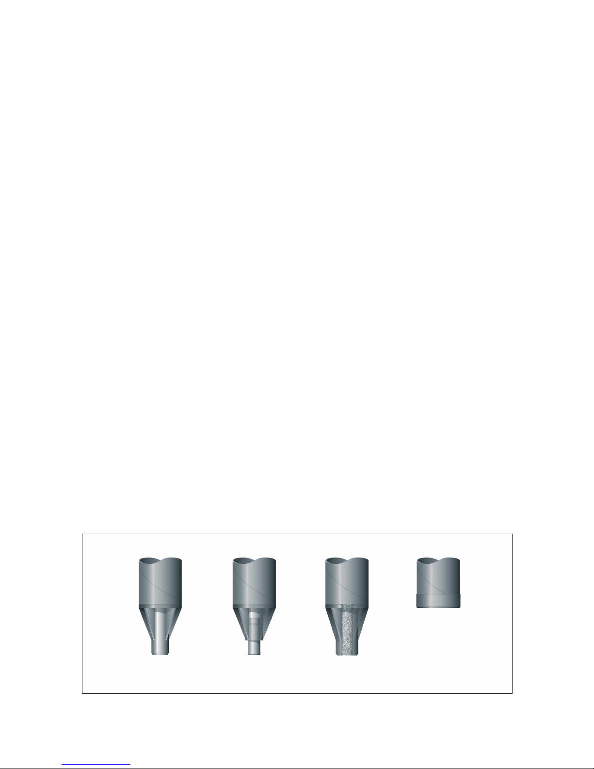
2.3 Small diameter RR and RRs piles
2.3.1 Structure, steel grades and identification
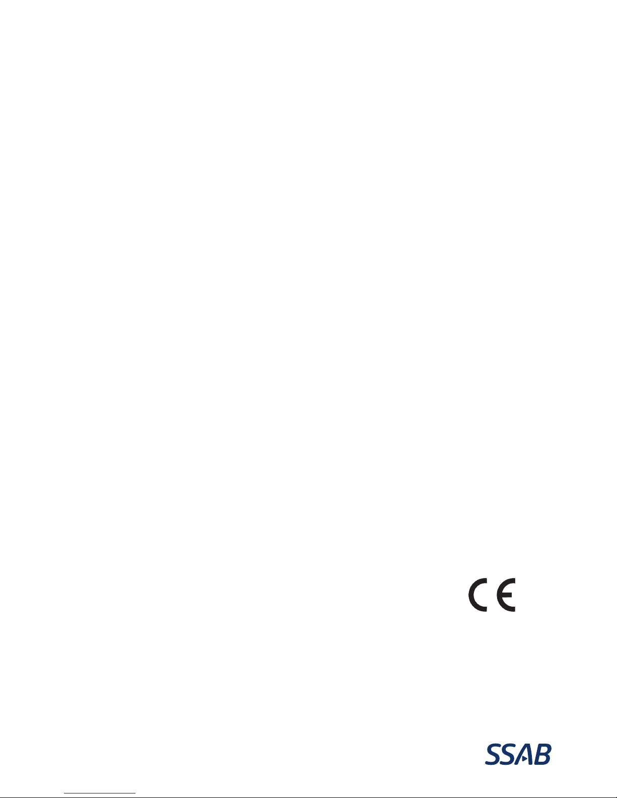
The structure and members of RR and RRs piles are shown
in Figure 1.
The basic steel grade of RR piles is S460MH and that
of RRs piles S550J2H. Against special order, the piles
may also be delivered in S420MH steel grade. RR270
to RR320 piles made of steel grade S355J2H are also
available.
RR and RRs piles have mechanical friction splices and pile
shoes up to pile size RR220/12.5. RR270 and RR320 piles
are spliced, if necessary, by welding, and the pile shoe is
attached by welding.
SSAB's RR small diameter piles are identified by a marking
on the side of the pile. In addition, identification tape is
attached to splices of RR pile sections or next to them.
Pile bundles are delivered with product descriptions that
indicate, besides pile manufacturer and dimensions, the
steel grade of the RR piles.
2.3.2 Pile sections, pipes and splices
A pile section consists of a pile pipe and the attached
external splice sleeve. The mill lengths of RR pile sections
and pile pipes without external splice sleeves are presented
in Table 2.
All pile sizes RR75 to RR220 made of steel grade S460MH
can be spliced using external splice sleeves and pile sizes
RR140 to RR220 by separate internal splices. RRs piles are
manufactured in eight different sizes. All RRs pile sizes can
be joined by external splice sleeves.
External
splice
Internal
splice
Rock shoe
Bottom plate
Bearing
plate
Figure 1. Structure and parts of RR piles, pile sizes RR75
to RR220.
The splices meet the requirements of PO-2016 for rigid
splices and those of the national appendix to Eurocode
EN 1993-5: Design of steel structures, Steel piles (Table
3). Since the splices meet the requirements, pile splices do
not limit the structural capacity of the pile, and piles can be
installed as straight as possible in all soil conditions.
Table 2. Mill dimensions of RR and RRs pile sections and pile pipes.
Length of pile section (incl. splice) Length of pile section (excl. splice)
Pile type 12 m 6 m 4 m 3 m 2 m 1.5 m 1.2 m 1.0 m 6 m 12 m 16 m
RR75 - X O O O O O O X O -
RR90 - X O O O O O O X O -
RR115/6.3 O X O O O O O O X O -
RR115/8 O X O O O O O O O X O
RR140/8 X X O O O O O O O X O
RR140/10 X X O O O O O O O X O
RR170/10 X X O O O O O O O X O
RR170/12.5 X O O O O O O O O X O
RR220/10 X O O O - - - - O X O
RR220/12.5 X O O O - - - - O X O
RRs100/6.3 - X O O O O O O X O -
RRs115/8 O X O O O O O O O X O
RRs125/6.3 X X O O - - - - O X -
RRs140/8 X X O O O O O O O X O
RRs140/10 X O O O O O O O O X O
RRs170/10 X O O O O O O O O X O
RRs220/10 X O O O - - - - O X O
RRs220/12.5 X O O O - - - - O X O
X = stock size O = project-specific size – = not in production
6
Table 3. Minimum strength and stiness requirements of
RR and RRs pile splices
Pile type
Tensile
strength
[kN]
Com-
pression
strength
Yield
moment
M
Flexural
stiffness
EI(0.3-0.8 M)
RR75 95
Ppile Mpile 0.75xEIpile
RR90 113
RRs100/6.3 156
RR115/6.3 147
RR115/8 184
RRs115/8 220
RRs125/6.3 197
RR140/8 228
RRs140/8 273
RR140/10 281
RRs140/10 336
RR170/10 343
RRs170/10 410
RR170/12.5 422
RR220/10 453
RRs220/10 542
RR220/12.5 560
RRs220/12.5 669
2.3.3 Pile shoes
The mechanically attached pile shoes of RR and RRs piles,
bottom plates and rock shoes, meet the requirements
given in PO-2016. The rock shoe dowel is made of
hardened special steel, which ensures good penetration
into bedrock. The foundation engineer chooses the
type of pile shoe according to the conditions. Use of a
rock shoe is always recommended when piles are driven
through to an inclined bedrock surface or a bedrock
surface under thin coarse-grained or moraine soil
layers. Rock shoes make it possible for piles to penetrate
compact or rocky soil layers better and remain straighter.
SSAB's pile shoes are dimensioned to withstand the
stresses from pile installation and use, provided that the
instructions of Sec. 7.3 are observed in installation.
Jacked RR micropiles can be equipped with a special shoe
through which post-grouting can be done after jacking to
improve point, and to some extent, shaft resistance.
The shoes used with RR270 to RR320 piles are rock shoes
with hardened rock dowels. Against special order, the pile
tip can be protected by a bottom plate or a rock shoe
different from the standard rock shoe. All shoes of RR270
to RR320 piles are attached to the pipe pile by welding.
Pipe piles are delivered to site with welded-on rock shoes.
The design resistance values of standard rock shoes for
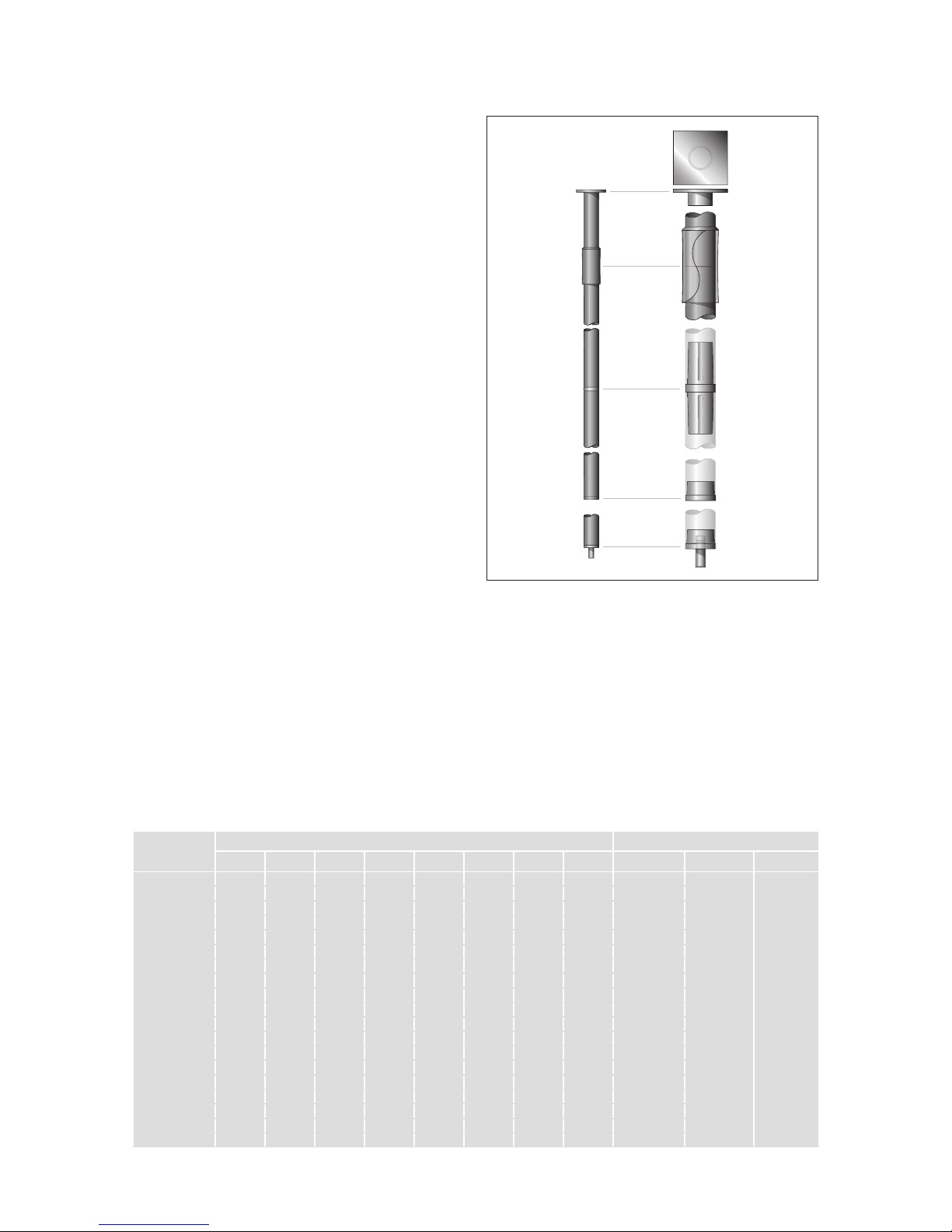
RR270 to RR320 piles are presented in Table 4. The most
Figure 2. Large diameter RR pile
7
important dimensioning factor for rock shoes are the end
blows and/or dynamic load test. Moreover addition, the
installation instructions of Sec. 7.3 must be followed in
installation, especially if the pile tip encounters a boulder
or an inclined bedrock surface.
RR270 to RR320 rock shoes have the Finnish Transport
Agency’s permission for use (565/090/201, 4.10.2011).
With steel grade S460MH, the calculated resistance of
the rock shoe limits the ultimate geotechnical resistance
Rcof pile sizes RR270/12.5 and RR320/12.5 to that
presented in Table 4 and with steel grade S550J2H and
all pile dimensions RR270 to RR320 to the Rd,L values
presented in Table 4.
Table 4. Structural resistances of RR270 and RR320
standard rock shoes
Pile Rd,L [kN]
RR270 4073
RR320 4777
Rd,L = design value of ultimate limit state of the structural
resistance of a rock shoe for a centric vertical load at
the installation stage (impact and PDA measurement)
2.4 Large diameter RR piles
2.4.1 Structure, dimensions and availability of
steel grades
Large diameter RR piles are made of spirally welded steel
pipes. It is possible to manufacture single-section piles
up to 39 metres long. Piles are usually ordered in specific
lengths. The standard stocked sizes are presented in
Table 5.
Table 5. Large diameter RR piles in stock (L=12 m)
Dimensions
diameter x wall thickness [mm]
Steel grade
406 x 12.5 S440J2H (S355J2H)
508 x 12.5 S440J2H (S355J2H)
610 x 12.5 S355J2H
711 x 12.5 S355J2H
813 x 12.5 S355J2H
The main steel grades used for RR large diameter piles
are S355J2H, S440J2H and S550J2H. Against special
order, the piles may also be delivered in MH steel grades
according to standard EN10219 or X grades according to
API5L. Standard dimensions and the availability of steel
grades are presented in Table 6. The diameters primarily
recommended for design are RR400, RR500, RR600,
RR700, RR800, RR900, RR1000 and RR1200. In the case
of end-bearing piles, the recommended minimum wall
thickness to ensure easy installation is 10 mm for piles
RR400 to RR800 and 12.5 mm for RR900 to RR1200.
Besides the standard dimensions presented in Table
6, RR piles can also be made with other diameters
and customer-specific wall thicknesses selectable at
0.1 mm intervals. The selection of wall thicknesses and
steel grades allows accurate optimisation of structures.
Customer- or project-specific deviations from standard
dimensions require a quite large project, and optimisation
is particularly useful with combi wall or RD pile wall
structures, but also in end-bearing pile projects.
RR large diameter piles are recognised from a marking
on the side. Pile bundles are delivered with product
descriptions that indicate, besides pile manufacturer and
dimensions, the steel grade of the RR piles.
Table 6. Standard dimensions and availability of steel grades of large diameter steel pipe piles.
Pile Diameter Wall thickness [mm]
[mm] 8 10 12.5 14.2 16 18 20 21 22 23
RR400 406.4
RR450 457.0
RR500 508.0
RR550 559.0
RR600 610.0
RR650 660.0
RR700 711.0
RR750 762.0
RR800 813.0
RR900 914.0
RR1000 1016.0
RR1200 1220.0
Steel grades S440J2H, S550J2H and S355J2H
Steel grades S440J2H and S355J2H
Check availability from SSAB sales.
8
structure used as a wharf where the penetration level of
the piles is close to the bottom of the waterway and piles
are subject to considerable horizontal loads. There, rock
dowels drilled through the hollow dowel ensure the stability
of the retaining structure. Rock shoes with a hollow dowel
are also used at sites where piles are subject to tension
forces. A pull anchor can be installed through the hole.
In conditions of no or few stones, where the pile tip is
designed to bear on soil layers, the tip of the pile can be
protected by a so-called reinforced bottom plate. The
recommended solution for such conditions, however, is to
use standard rock shoes with structural steel dowels.
Open ended piles are often equipped with a so-called
reinforcement ring to protect the lower end. The
reinforcement ring is usually a 150 to 500 mm wide steel
band welded onto the lower end of the pile. The sheet
thickness of the steel band is usually 10, 15 or 20 mm.
Both reinforcement rings and reinforced bottom plates
are manufactured to the client’s project-specific designs.
Rock shoes are preheated before welding and assembly
welding is carried out by robots. The rock shoes are
numbered to ensure the traceability of the manufacture
and raw-materials of the shoes.
The design resistance values of standard rock shoes for
RR large diameter piles are presented in Table 7. The
most important criterion for rock shoes are the end blows
and/or the dynamic load test. Project specific rock shoes
with different capacities are analyzed numerically by the
requirements of Finnish Transport Agency. Moreover, the
installation instructions of Sec. 7.3 must be followed in
installation, especially if the pile tip encounters a boulder
or an inclined rock surface.
At the design stage, however, the maximum impact
resistance of each pile size should be limited to its/the Rd,L
value.
Figure 3. Shoe types of large diameter RR piles.
Rock shoe with structural
steel dowel
Rock shoe with hardened
steel dowel
Rock shoe with
hollow dowel
Toe
reinforcement
2.4.2 Pile shoes
In soil conditions typical of the Nordic countries,
RR large diameter piles are usually equipped with
RR rock shoes. SSAB's standard rock shoes were
granted the Finnish Transport Agency’s use permission
(565/090/201, 4 October 2011) and the manufactured
rock shoes are CE marked. Rock shoes are used to protect
the lower end of the pile against installation stresses, to
centre the stresses on the pile tip as evenly as possible
across the pile pipe cross-section, and to prevent lateral
sliding of the pile tip.
There are three types of RR rock shoes (Figure 3). The most
common ones are rock shoes fitted with a structural steel
dowel or a hardened rock dowel. SSAB also delivers rock
shoes fitted with a hollow dowel, which allows drilling, for
example, a dowel bar to be grouted to bedrock through the
concrete filled hollow dowel of the rock shoe.
A rock shoe with a structural steel dowel is used in
conditions where the target level of the piles is within
coarse-grained or moraine soil layers, or in conditions
where the bedrock surface is relatively even and there
are supporting compact soil layers on top of the bedrock.
A rock shoe with a structural steel dowel endures well
penetration to the surface of the bedrock and into it.
A rock shoe with a hardened rock dowel is used in
conditions where the bedrock surface is inclined or there
are no compact coarse-grained or moraine soil layers on
top of the bedrock – or the soil layers are thin and the
pile tip is to be driven to the bedrock surface. Rock shoes
with a hardened rock dowel can prevent lateral sliding of
the pile tip in most conditions.
Rock shoes with a hollow dowel can be used in conditions
where it is desired to ensure the staying in place of the pile
tip by a grouted steel dowels drilled through the hollow
dowel into bedrock. A typical application is a combi-wall

9
Table 7. Design values of ultimate limit state of the structural
resistance of a rock shoes for a centric vertical load at the
installation stage (impact and PDA measurement)
Pile Structural
steel dowel
Rd,L [kN]
Hardened
steel dowel
Rd,L [kN]
Hollow
dowel
Rd,L [kN]
RR400 5033 4982
RR450 6057 6032
RR500 7672 7545
RR550 7994 7940
RR600 9677 9681 9285
RR650 10084 10062
RR700 11993 11605 11370
RR750 12387 12342
RR800 12653 12610 12188
RR900 14910 14887 14512
RR1000 18751 15691 18371
RR1200 19317 19260
2.5 RD and RDs piles
2.5.1 Structure, dimensions, steel grade selection
and identification
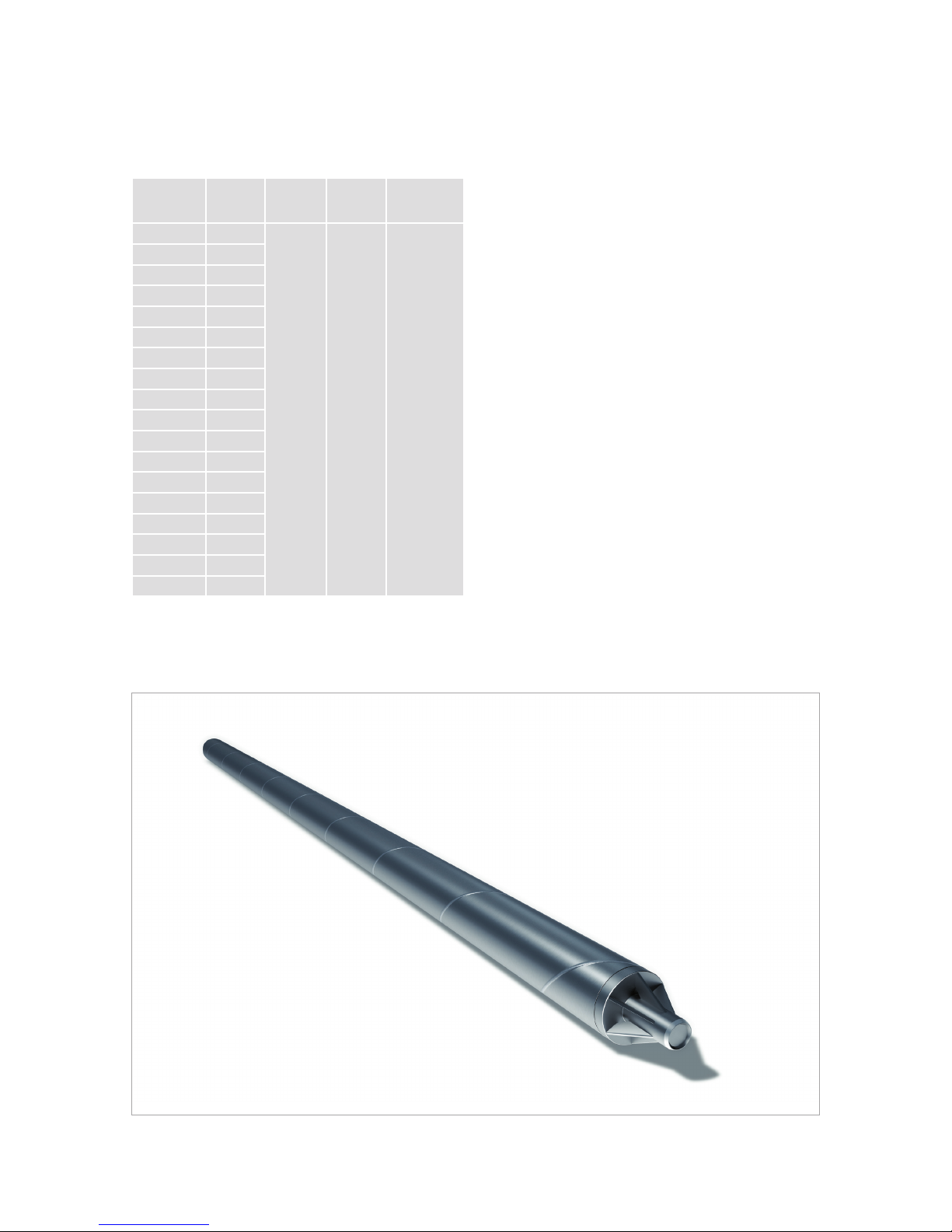
The structure of the RD pile is shown in Figure 4. The
standard steel grade of RD90 to RD220 piles is S460MH.
The steel grade of RDs piles is S550J2H. Against special
order, the piles may also be delivered in S420MH steel
grade. RD270 to RD320 piles made of S355J2H steel
grade are also available. All steel grades of SSAB's steel
pile products can be used as steel grades of RD400 to
RD1200 piles. The pile sizes and availability of steel grades
Threaded
pile section
Threaded
splice sleeve
Bearing plate
Welded splice
(beveled ends)
Casing shoe /
ring bit
Figure 4. Structure of RD micropile.
of RD piles are presented in Table 8. Dimensions RD400,
RD500, RD600, RD700, RD800, RD900, RD1000 and
RD1200 are recommended for RD large diameter piles.
Table 8. Standard dimensions and availability of steel grades of RD piles.
Pile Diameter Wall thickness [mm]
[mm] 6.3 8 10 12.5 14.2 16 18 20 21 22 23
RD90 88.9
RDs100 101.6
RD115 114.3
RDs125 127.0
RD140 139.7
RD170 168.3
RD220 219.1
RD270 273.0
RD320 323.9
RD400 406.4
RD450 457.0
RD500 508.0
RD550 559.0
RD600 610.0
RD650 660.0
RD700 711.0
RD750 762.0
RD800 813.0
RD900 914.0
RD1000 1016.0
RD1200 1220.0
Steel grades S440J2H and S550J2H
Steel grades S550J2H
Steel grades S460MH, S550J2H and S355J2H
Steel grades S440J2H, S550J2H and S355J2H
Steel grades S440J2H and S355J2H
Check availability from SSAB sales.

10
Figure 5. Structure of large diameter RD piles.
a top hammer is used. Instructions for the handling and
installation of splices, as well as the dimensions of threaded
sleeves and recommended types and dimensions of ring
bits are presented in Sec. 7.4.4 of these instructions. The
sleeves meet the requirements for rigid splices of Piling
Manual PO-2016 and the National Annex to Eurocode
1993-5, Design of steel structures, Steel piles (Table 10).
The splice is guaranteed a tensile strength that is 50 % of
the compressive strength of the pile when the handling and
installation of the splice are done according to Secs. 7 and 8.
All RD piles may also be spliced by welding.
The piles are delivered either as pile pipes or RD pipe sections
with threaded ends. The lengths of pile pipes and sections are
shown in Table 9. The inside burr of the longitudinal seam of
RD90-RD320 piles can be removed in individual projects to
order. With the most commonly used pilot bits the removal
of the inside burr is usually not necessary, but the pilot bit
should be selected considering the effect of the burr.
RD piles can be identified by the marking on their side.
Pile bundles are delivered with product descriptions that
indicate, besides pile manufacturer and dimensions, the
steel grade of the RD piles. If these markings are missing,
the pile pipe must not be used in RD piles.
2.5.2 Splicing and steel grade selection of RD piles
RD-piles are spliced using external threaded sleeves (t≥8mm
and D≤220mm) (Figure 6), by threaded and welded splice
pieces (RD270/10, RD270/12,5, max fy= 460 MPa ;
RD320/10, RD320/12,5, max fy= 550 MPa) or by welding.
Mechanized welding is used specially in underpinning
projects. When using a DTH hammer, the threads of the pile
pipe and the sleeve are left-handed, but right-handed when
RD®RDs®
Figure 6. Splice sleeves of RD and RDs piles
Table 9 a. and table 9 b. Length range of RD and RDs piles
Pile type Lenght of pile pipe without threads
1 m 1.2 m 1.5 m 2 m 3 m 4 m 6 m 12 m 12-16 m 16-34 m
RD90 O O O O O O X - - -
RD115/6.3 O O O O O O X O - -
RD115/8 O O O O O O O X O -
RD140-RD320 O O O O O O O X O -
RD400-RD1200 O O O O O O O X O O
RDs90 O O O O O O O - - -
RDs100 O O O O O O O - - -
RDs115/6.3 O O O O O O O O - -
RDs115/8 O O O O O O O X O -
RDs125/6.3 O O O O O O O X - -
RDs140-RDs320 O O O O O O O X O -
X = stock sizes
O = project-specific size
-= not available
Pile type
Length of pile section with threaded ends
1 m 1.2 m 1.5 m 2 m 3 m 4 m 6 m 12 m
RD115/8 O O O O X O O O
RD140/8 O O O O O O O O
RD140/10 O O O O O O X O
RD170/10 O O O O O O X O
RD170/12.5 O O O O O O X O
RD220/10 O O O O O O O O
RD220/12.5 O O O O O O X O
RDs115/8 O O O O O O O O
RDs140/8 O O O O O O O O
RDs140/10 O O O O O O O O
RDs170/10 O O O O O O O O
RDs170/12.5 O O O O O O X O
RDs220/10 O O O O O O O O
RDs220/12.5 O O O O O O X O
Pile type
Length of pile section with threaded splice pieces
6 m 12 m
RD270/10 O O
RD270/12.5 O O
RD320/10 0 O
RD320/12.5 0 O
RDs320/10 0 O
RDs320/12.5 0 O
11
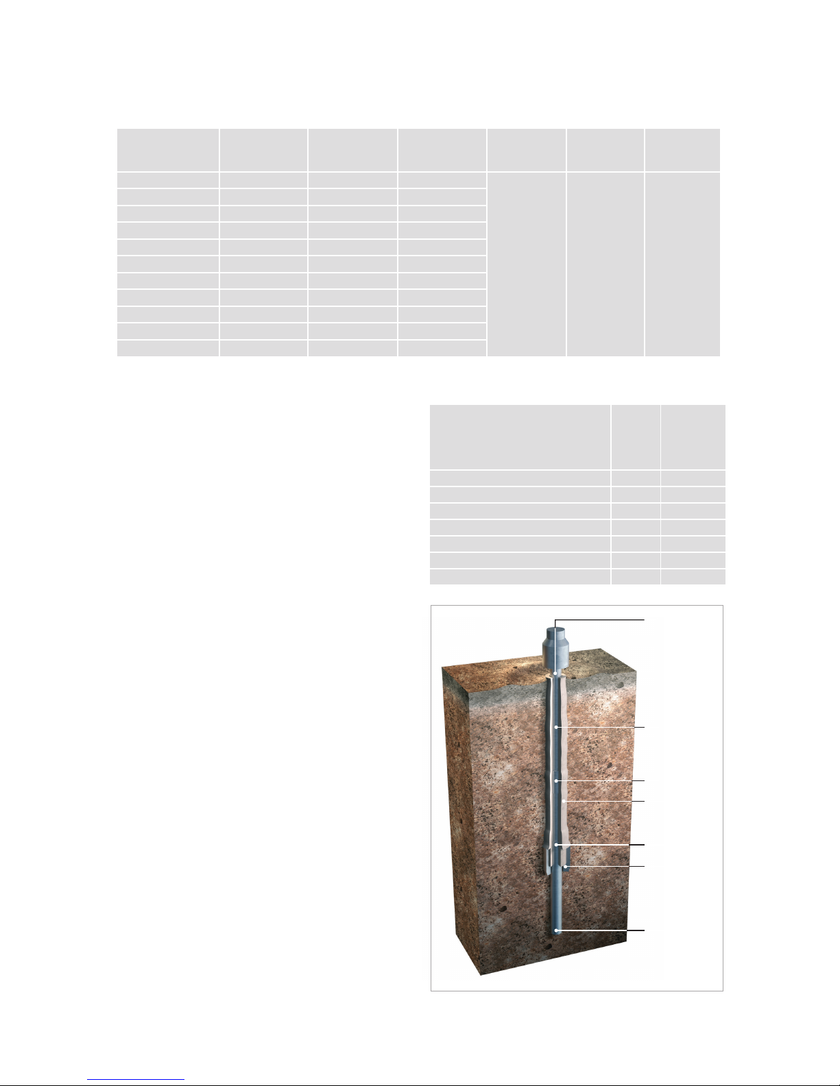
Grouting,
pressurised
if necessary
RR pile
section
Splice
Grout mantle
Grouting holes
Collar
Pile toe
2.6 Shaft grouted RR piles (CSG-RR piles)
Shaft grouted RR®piles are for the most part shaft-
bearing micropiles where the geotechnical bearing
capacity of the pile shaft is improved by Continuous
Shaft Grouting using cement grout. Shaft grouted piles
are suitable for use in friction soil layers where their
high shaft resistance can be used to shorten pile length
considerably.
Shaft grouted RR piles have all the mechanical
components of RR micropiles as well as a so-called
collar. The splice type is the external RR pile splice
sleeve. The length of a pile section is usually 6 metres,
but the other section lengths presented in Table 2 are
also possible. The most common shaft grouted pile sizes
are RR90 to RR140. The standard steel grade of shaft
grouted RR piles is S460MH. RRs100/6.3, RRs115/8,
RRs125/6.3, RRs140/8, RRs140/10 and RRs170/10 pile
sections of steel grade S550J2H may also be used. The
pile structure is shown in Figure 7.
Shaft grouted driven RR piles are equipped either with
a bottom plate or a rock shoe, usually a bottom plate. A
rock shoe is used especially to ensure contact between
the pile tip and bedrock or penetration of compact soil/fill
layers in top soil. The lower end of a shaft grouted driven
RR pile has a collar larger than the pile pipe. The purpose
of the collar is to keep the grouting holes open during
installation and to make a hole larger than the pile pipe in
the ground. A guide device directs the tip of the pile and
protects the collar from possible obstructions. The length
of the guide device is usually 0.5 to 1.0 m. Table 11 shows
the diameters of pre-dimensioned shoe collars. The collar
of a pre-dimensioned shoe is detachable and installed
in the shoe at the beginning of the installation stage. If
necessary, the collars and shoes can be designed case by
case. It is recommended that the outer diameter of the
collar is at least 40 mm larger than the diameter of the
pile pipe.
Table 10. Strengths of threaded sleeves and threaded M/F splices.
Figure 7. Grouted RR pile (CSG-RR pile)
Table 11. Diameters of CSG-RR pile collars.
Pile size
Pile
diameter
d[mm]
Diameter of
standard
collar
[mm]
CSG-RR75 76.1 127.0
CSG-RR90 88.9 139.7
CSG-RRs100/6,3 101,6 152,4
CSG-RR115/6.3 and CSG-RR115/8 114.3 159
CSG-RRs125/6.3 127.0 168.3
CSG-RR140/8 and CSG-RR140/10 139.7 193.7
CSG-RR170/10 and CSG-RR170/12.5 168.3 219.1
Pile Tensile strength
[kN] Pile Tensile
strength [kN]
Compression
strength
Bending
strength
Flexural
stiness
EI
(0.3 –0.8 M)
RD115/8 620 RDs115/8 750
Ppile Mpile 0.75 x EIpile
RD140/8 770 RDs140/8 910
RD140/10 940 RDs140/10 1120
RD170/10 1150 RDs170/10 1370
RD170/12.5 1410 RDs170/12.5 1680
RD220/10 1520 RDs220/10 1810
RD220/12.5 1870 RDs220/12.5 2230
RD270/10 1900
RD270/12.5 2350
RD320/10 2270 RDs320/10 2720
RD320/12.5 2820 RDs320/12.5 3370

12
2.7 Bearing plates
Usually a bearing plate is installed at the upper end of RR/
RRs, RD/RDs and CSG-RR micropiles to transfer loads
from the superstructure to the pile. Standard bearing
plates are centralized on the pile shaft by an internal
sleeve, which serves to keep the bearing plate in place
during the construction phase. It is not designed to
withstand possible horizontal loads of the pile. The plate
of standard bearing plates is made of steel S355J2. The
standard sizes of bearing plates are shown in Table 12.
Table 12 presents the suggested design strengths Rdof
the bearing plates. It is recommended that the strength of
the bearing plate be verified both as to the steel structure
of the bearing plate and the compressive strength and
punching shear capacity of the concrete on top of the
bearing plate when the design value of load is about 90
to 100% of the design value of the strength of the bearing
plate and when using concrete strengths C30/37 to
C35/45.
Bearing plates may also be made based on specific site
designs in dimensions and shapes different from standard
bearing plates, for example, with a hole.
2.8 Pile dimensions and geometrical sectional
properties
The dimensions and geometrical sectional properties of
longitudinally welded RR and RD micropiles are presented
in Table 13 and those of spirally welded large diameter RR
and RD piles in Table 14.
Table 13. Dimensions and geometrical sectional properties of RR®and RD®micropiles.
A
Au
Ab
= Area of steel cross-section
= Pile surface area
= Area of pile toe
Z
I
Wel
= Pile impedance
= Moment of inertia
= Elastic modulus
Sectional properties incl. corrosion allowances
of 1.2 mm and 2.0 mm
D
[mm]
t
[mm]
M
[kg/m]
A
[mm2]
Au
[m2/m]
Ab
[mm2]
Wel
[cm3]
I
[cm4]
EI
[kNm2]
Z
[kNs/m]
A1,2
[mm2]
A2,0
[cm4]
I1,2
[cm4]
I2,0
[cm4]
EI1,2
[kNm2]
EI2,0
[kNm2]
76.1 6.3 10.8 1382 0.24 4548 22.3 84.8 178 56.1 1099 916 65.0 52.8 137 111
88.9 6.3 12.8 1635 0.28 6207 31.6 140.2 295 66.4 1304 1089 108.4 88.7 228 186
101.6 6.3 14.8 1886 0.32 8107 42.3 215.1 452 76.6 1508 1260 167.4 137.4 351 289
114.3 6.3 16.8 2138 0.36 10261 54.7 312.7 657 86.8 1711 1432 244.5 201.4 514 423
114.3 8.0 21.0 2672 0.36 10261 66.4 379.5 797 108.5 2245 1966 311.3 268.2 654 563
127.0 6.3 18.7 2389 0.40 12667 68.7 436.2 916 96.9 1914 1603 342.3 282.7 719 593
139.7 8.0 26.0 3310 0.44 15328 103.1 720.3 1513 134.4 2788 2445 595.1 515.2 1250 1082
139.7 10.0 32.0 4075 0.44 15328 123.4 861.9 1810 165.4 3553 3210 736.7 656.8 1547 1379
168.3 10.0 39.0 4973 0.53 22246 185.9 1564.0 3284 201.9 4343 3928 1344.1 1202.7 2823 2526
168.3 12.5 48.0 6118 0.53 22246 222.0 1868.4 3924 248.4 5488 5073 1648.5 1507.1 3462 3165
219.1 10.0 51.6 6569 0.69 37703 328.5 3598.4 7557 266.7 5748 5205 3110.9 2794.7 6533 5869
219.1 12.5 63.7 8113 0.69 37703 396.6 4344.6 9124 329.4 7292 6749 3857.0 3540.9 8100 7436
273.0 10.0 64.9 8262 0.86 58535 524.1 7154.1 15024 335.5 7238 6560 6207.9 5590.9 13037 11741
273.0 12.5 80.3 10230 0.86 58535 637.2 8697.4 18265 415.3 9205 8527 7751.2 7134.2 16278 14982
323.9 10.0 77.4 9861 1.02 82397 750.7 12158.3 25533 400.4 8645 7839 10574.7 9538.5 22207 20031
323.9 12.5 96.0 12229 1.02 82397 916.7 14846.5 31178 496.5 11012 10206 13262.9 12226.7 27852 25676
Table 12. Dimensions of standard bearing plates,
suggested design strengths of bearing plates.
Pile
Bearing plate
dimensions
[mm x mm x mm]
Suggested
design
resistance
Rd[kN]
RR75** 150 x 150 x 15 380
RR/RD90** 150 x 150 x 15 450
RRs100/6,3 200 x 200 x 20
200 x 200 x 25 700
780
RR/RD115/6.3** 200 x 200 x 20 780
RR/RD115/8** 250 x 250 x 25 910
RRs125/6.3 200 x 200 x 20
250 x 250 x 25
950
1080
RR/RD140/8 and
RR/RD140/10** 250 x 250 x 25 1240
RR/RD170/10 and
RR/RD170/12.5** 300 x 300 x 30 1810
RR/RD220/10** 300 x 300 x 30 2090
RR/RD220/12.5 300 x 300 x 30 2090
RRs/RDs220/12.5 350 x 350 x 35 2700
RR/RD270/10 350 x 350 x 35* 2700
RR/RD270/12.5 350 x 350 x 35* 2700
RR/RD320/10 400 x 400 x 30* 3480
RR/RD320/12.5 400 x 400 x 30* 3480
RR/RD270/10 S550J2H 400 x 400 x 30* 2950
RR/RD270/12.5
S550J2H 450 x 450 x 40* 3750
RR/RD320/10 S550J2H 450 x 450 x 40* 4050
RR/RD320/12.5
S550J2H 500 x 500 x 40* 4520
*) Product not in stock
**) Pile sizes RR75 to RR220/10 of steel grades S440J2H
and S550J2H with same bearing plates

13
Table 14. Dimensions and geometrical sectional properties of RR®and RD®large diameter piles
A
Au
Ab
= Area of steel cross-section
= Pile surface area
= Area of pile toe
Z
I
Wel
= Pile impedance
= Moment of inertia
= Elastic modulus
Sectional properties incl. corrosion allowances
of 1.2 mm and 2.0 mm
D
[mm]
t
[mm]
M
[kg/m]
A
[mm2]
Au
[m2/m]
Ab
[mm2]
Wel
[cm3]
I
[cm4]
EI
[kNm2]
Z
[kNs/m]
A1,2
[mm2]
A2,0
[cm4]
I1,2
[cm4]
I2,0
[cm4]
EI1,2
[kNm2]
EI2,0
[kNm2]
406.4 8.0 78.6 10013 1.28 129717 978.0 19873.9 41735 406.5 8485 7472 16738.8 14679.5 35151 30827
406.4 10.0 97.8 12453 1.28 129717 1204.5 24475.8 51399 505.6 10926 9912 21340.7 19281.4 44815 40491
406.4 12.5 121.4 15468 1.28 129717 1477.9 30030.7 63064 628.0 13941 12927 26895.6 24836.3 56481 52156
457.0 8.0 88.6 11285 1.44 164030 1244.9 28446.4 59737 458.2 9566 8426 23984.0 21048.1 50366 44201
457.0 10.0 110.2 14043 1.44 164030 1535.7 35091.3 73692 570.2 12325 11184 30628.9 27693.0 64321 58155
457.0 12.5 137.0 17455 1.44 164030 1888.2 43144.8 90604 708.7 15737 14597 38682.4 35746.5 81233 75068
508.0 8.0 98.6 12566 1.60 202683 1546.5 39280.0 82488 510.2 10656 9387 33145.8 29104.6 69606 61120
508.0 10.0 122.8 15645 1.60 202683 1910.2 48520.2 101893 635.2 13735 12466 42386.1 38344.9 89011 80524
508.0 12.5 152.7 19458 1.60 202683 2352.6 59755.4 125486 790.0 17548 16279 53621.3 49580.1 112605 104118
508.0 14.2 172.9 22029 1.60 202683 2645.6 67198.6 141117 894.4 20118 18849 61064.5 57023.3 128235 119749
508.0 16.0 194.1 24731 1.60 202683 2949.2 74909.0 157309 1004.1 22820 21551 68774.9 64733.7 144427 135941
559.0 8.0 108.7 13848 1.76 245422 1880.7 52564.9 110386 562.3 11745 10348 44386.4 38992.4 93211 81884
559.0 10.0 135.4 17247 1.76 245422 2325.6 65001.1 136502 700.3 15144 13748 56822.5 51428.6 119327 108000
559.0 12.5 168.5 21461 1.76 245422 2868.0 80161.8 168340 871.4 19358 17961 71983.2 66589.3 151165 139837
559.0 14.2 190.8 24304 1.76 245422 3228.3 90230.7 189485 986.8 22201 20804 82052.1 76658.2 172309 160982
559.0 16.0 214.3 27294 1.76 245422 3602.3 100683.0 211434 1108.2 25191 23794 92504.4 87110.5 194259 182932
610.0 8.0 118.8 15130 1.92 292247 2247.6 68551.4 143958 614.3 12835 11310 57918.1 50898.9 121628 106888
610.0 10.0 148.0 18850 1.92 292247 2781.9 84846.6 178178 765.3 16554 15029 74213.3 67194.1 155848 141108
610.0 12.5 184.2 23464 1.92 292247 3434.6 104754.7 219985 952.7 21169 19644 94121.5 87102.3 197655 182915
610.0 14.2 208.6 26579 1.92 292247 3869.0 118003.9 247808 1079.2 24284 22759 107370.6 100351.4 225478 210738
610.0 16.0 234.4 29858 1.92 292247 4320.7 131781.4 276741 1212.3 27563 26038 121148.2 114129.0 254411 239671
610.0 18.0 262.8 33477 1.92 292247 4812.8 146790.8 308261 1359.2 31182 29657 136157.5 129138.3 285931 271190
660.0 8.0 128.6 16387 2.07 342119 2639.0 87087.9 182885 665.3 13903 12252 73613.7 64712.5 154589 135896
660.0 10.0 160.3 20420 2.07 342119 3268.8 107870.5 226528 829.1 17937 16286 94396.3 85495.1 198232 179540
660.0 12.5 199.6 25427 2.07 342119 4039.6 133306.4 279943 1032.4 22944 21293 119832.2 110931.0 251648 232955
660.0 14.2 226.2 28810 2.07 342119 4553.4 150263.1 315552 1169.7 26326 24675 136788.9 127887.6 287257 268564
660.0 16.0 254.1 32371 2.07 342119 5088.5 167921.2 352634 1314.3 29887 28237 154447.0 145545.7 324339 305646
660.0 18.0 285.0 36304 2.07 342119 5672.4 187188.3 393095 1474.0 33821 32170 173714.1 164812.9 364800 346107
711.0 8.0 138.7 17668 2.23 397035 3070.7 109162.2 229241 717.4 14992 13214 92310.2 81170.3 193851 170458
711.0 10.0 172.9 22023 2.23 397035 3805.9 135301.4 284133 894.2 19347 17568 118449.4 107309.5 248744 225350
711.0 12.5 215.3 27430 2.23 397035 4707.3 167343.2 351421 1113.7 24754 22975 150491.3 139351.4 316032 292638
711.0 14.2 244.0 31085 2.23 397035 5309.0 188735.2 396344 1262.1 28409 26630 171883.3 160743.4 360955 337561
711.0 16.0 274.2 34935 2.23 397035 5936.4 211039.8 443184 1418.4 32259 30480 194187.9 183047.9 407794 384401
711.0 18.0 307.6 39188 2.23 397035 6621.9 235410.0 494361 1591.1 36512 34733 218558.1 207418.2 458972 435578
711.0 20.0 340.8 43417 2.23 397035 7295.4 259350.9 544637 1762.8 40741 38962 242498.9 231359.0 509248 485854
762.0 8.0 148.8 18950 2.39 456037 3535.0 134683.0 282834 769.4 16082 14175 113931.3 100205.7 239256 210432
762.0 10.0 185.5 23625 2.39 456037 4383.9 167028.4 350760 959.2 20757 18850 146276.7 132551.0 307181 278357
762.0 12.5 231.0 29433 2.39 456037 5426.0 206731.0 434135 1195.0 26565 24658 185979.3 172253.7 390557 361733
762.0 14.2 261.9 33360 2.39 456037 6122.6 233271.2 489870 1354.5 30492 28585 212519.5 198793.9 446291 417467
762.0 16.0 294.4 37498 2.39 456037 6849.7 260973.3 548044 1522.5 34630 32723 240221.6 226496.0 504465 475642
762.0 18.0 330.3 42072 2.39 456037 7645.1 291276.4 611680 1708.2 39204 37297 270524.7 256799.1 568102 539278
762.0 20.0 366.0 46621 2.39 456037 8427.4 321082.8 674274 1892.9 43753 41846 300331.1 286605.4 630695 601871
813.0 8.0 158.8 20232 2.55 519124 4032.0 163900.5 344191 821.4 17171 15136 138689.6 122006.2 291248 256213
813.0 10.0 198.0 25227 2.55 519124 5002.8 203363.9 427064 1024.3 22167 20131 178153.0 161469.6 374121 339086
813.0 12.5 246.8 31436 2.55 519124 6195.8 251860.3 528907 1276.3 28375 26340 226649.4 209966.0 475964 440929
813.0 14.2 279.7 35635 2.55 519124 6994.2 284314.9 597061 1446.8 32575 30539 259103.9 242420.6 544118 509083
813.0 16.0 314.5 40062 2.55 519124 7828.3 318221.7 668266 1626.6 37001 34966 293010.8 276327.4 615323 580288
813.0 18.0 352.9 44956 2.55 519124 8741.7 355350.0 746235 1825.3 41896 39861 330139.1 313455.7 693292 658257
813.0 20.0 391.1 49826 2.55 519124 9641.1 391909.3 823010 2023.0 46765 44730 366698.4 350015.0 770067 735032
813.0 23.0 448.1 57083 2.55 519124 10964.2 445694.2 935958 2317.7 54022 51987 420483.2 403799.9 883015 847980
914.0 10.0 222.9 28400 2.87 656118 6349.0 290147.2 609309 1153.1 24959 22670 254307.1 230570.4 534045 484198
914.0 12.5 277.9 35402 2.87 656118 7871.1 359708.4 755388 1437.4 31961 29672 323868.3 300131.7 680124 630277
914.0 14.2 315.1 40141 2.87 656118 8891.6 406344.5 853323 1629.8 36699 34410 370504.4 346767.8 778059 728212
914.0 16.0 354.3 45138 2.87 656118 9959.3 455141.8 955798 1832.7 41697 39408 419301.7 395565.1 880534 830687
914.0 18.0 397.7 50668 2.87 656118 11130.5 508664.8 1068196 2057.2 47226 44937 472824.7 449088.1 992932 943085
914.0 20.0 440.9 56172 2.87 656118 12285.8 561461.2 1179068 2280.7 52731 50441 525621.1 501884.5 1103804 1053957
914.0 23.0 505.4 64381 2.87 656118 13989.2 639308.0 1342547 2614.0 60939 58650 603467.9 579731.3 1267283 1217436
1016.0 10.0 248.1 31604 3.19 810732 7871.1 399849.7 839684 1283.2 27779 25233 350602.3 317964.5 736265 667725
1016.0 12.5 309.3 39407 3.19 810732 9766.2 496123.1 1041858 1600.0 35582 33036 446875.7 414237.9 938439 869899
1016.0 14.2 350.8 44691 3.19 810732 11038.6 560762.0 1177600 1814.5 40865 38320 511514.6 478876.8 1074181 1005641
1016.0 16.0 394.6 50265 3.19 810732 12371.6 628479.4 1319807 2040.9 46440 43894 579232.0 546594.2 1216387 1147848
1016.0 18.0 443.0 56436 3.19 810732 13835.7 702854.2 1475994 2291.4 52610 50064 653606.9 620969.0 1372574 1304035
1016.0 20.0 491.3 62581 3.19 810732 15282.0 776323.9 1630280 2540.9 58755 56209 727076.6 694438.7 1526861 1458321
1016.0 23.0 563.2 71751 3.19 810732 17418.3 884847.4 1858180 2913.2 67925 65380 835600.1 802962.2 1754760 1686221
1220.0 10.0 298.4 38013 3.83 1168987 11405.5 695737.9 1461050 1543.4 33419 30360 610420.2 553821.4 1281883 1163025
1220.0 12.5 372.2 47418 3.83 1168987 14169.3 864326.6 1815086 1925.3 42824 39765 779008.9 722410.0 1635919 1517061
1220.0 14.2 422.3 53791 3.83 1168987 16028.9 977764.6 2053306 2184.0 49197 46139 892446.9 835848.1 1874139 1755281
1220.0 16.0 475.1 60520 3.83 1168987 17980.7 1096821.7 2303325 2457.2 55925 52867 1011504.0 954905.2 2124158 2005301
1220.0 18.0 533.6 67971 3.83 1168987 20128.6 1227843.9 2578472 2759.8 63377 60319 1142526.3 1085927.4 2399305 2280448
1220.0 20.0 591.9 75398 3.83 1168987 22254.8 1357545.0 2850845 3061.3 70803 67745 1272227.4 1215628.5 2671677 2552820
1220.0 23.0 679.0 86491 3.83 1168987 25403.9 1549638.8 3254242 3511.7 81896 78838 1464321.2 1407722.3 3075074 2956217
The table shows the pile dimensions of standard products. Other dimensions defined in standard EN 10219-2 are also available against order.

14
3. DESIGN STANDARDS AND
IMPLEMENTATION CONTROL
The Eurocode standards are followed in building
construction projects according to the decrees of the
Ministry of the Environment. In civil engineering projects,
the Eurocode standards are applied according to the
instructions of the Finnish Transport Agency. Instructions
of other authorities (such as municipalities/cities) are
observed where necessary.
The geotechnical class (GL1, GL2, GL3) of the site is
selected according to PO-2016 and RIL 207 (Application
Eurocode 7). The foundation engineer responsible for the
site determines the geotechnical class.
GL1 sites do not normally require piling. Most soil
conditions and sites belong to geotechnical class GL2.
Owing to the good and versatile properties of steel piles,
they have many applications at geotechnical class GL3
sites.
Piling class (PTL1, PTL2 or PTL3) is determined on the ba-
sis of consequence class (CC1 to CC3, cf. EN 1990 National
Annex) and geotechnical class.
4. RECOMMENDATIONS FOR THE
SELECTION AND DESIGN OF PILE TYPE,
PILE SIZE AND PILING CLASS FOR
DIFFERENT APPLICATIONS
Various applications and advantages of different SSAB's
steel pile types are presented in brochures on RR and RRs
piles, RD and RDs piles and RD pile walls.
The selection of a suitable pile type should be based
primarily on soil conditions, but superstructures and
ambient structures also play a major role. Some
instructions and recommendations for the selection of
pile type, pile size and piling class are given below.
Pile loads
SSAB's steel piles can be divided according to pile sizes
and applications based on pile loads, for example, as
follows:
RR75–RR/RD140/8 1 & 2 family houses and other struc-
tures subject to relatively light loads
RR/RD140/8–RR/RD270 multi-storey buildings of about 3 to
8 storeys
RR/RD220–RR/RD500 heavy multi-storey buildings
(>5 storeys) or industrial building
projects
RR/RD140–RR/RD270 pile slab projects
RR/RD220–RR/RD400 noise barrier piles
(single pile foundations)
RR/RD500–RR/RD1200 bridge and harbour construction and
buildings of more than 10 to 15 storeys
When selecting between RR and RD pile sizes, it should be
noted that the design strength of RD piles bearing on solid
bedrock is typically clearly higher (about 1.2 to 2.0 times)
than that of an RR pile of corresponding size. Owing to
the comprehensive pile size range, foundation structures
can always be optimised by using several (typically two or
three) pile sizes at a site.
Installability of piles
RD piles can be installed in all soil conditions. In very
exacting conditions, such as those involving thick fill
layers containing large boulders, the smallest RD piles
(pile sizes around RD90 to RD140) may pose the risk
of slightly higher pile bending in comparison to large
diameter RD piles. If the bedrock surface is particularly
inclined, close to ground level (<3 to 5 m), and in
conditions where there are no supporting friction soil
layers on top of the bedrock surface, an RD pile is a risk-
free solution in terms of support for the lower end of the
pile.
The penetrability of driven RR and RRs piles increases
with increasing pile size. When the amount/size of
stones and boulders in soil and fill layers – or the density
or thickness of the soil layer – increases, the risk of
deviations in the positions and verticality of driven piles
increases. The risk that piles bend or fail to reach a load-
bearing soil layer also increases. RR large diameter piles
have successfully penetrated rock fills several metres
thick, even ones over 20 metres thick. An RR170 or
RR220 pile is often rigid enough to penetrate relatively
thick layers of rocky fill and moraine all the way to a
bearing basal formation, provided that the size and
amount of stones and boulders is not exceptionally
large. A rock shoe improves the penetrability of a pile.
When building 1 & 2 family houses on thick moraine soils
containing stones it is recommended to use at least pile
size RR115/6.3.
Positional and verticality tolerances of piles
When a structure is set strict positional and verticality
tolerances, like, for instance, railway bridges built using
the bridge-moving technique, where a large diameter
pile is attached to the deck and also acts as a column,
the RD pile is the least risky alternative. It is also the
most recommendable alternative for corresponding
building construction projects where the pile also acts
as a column. Strict tolerances may also be required in
foundation underpinning or industrial building projects.
Environmental impacts of piling and nearby
structures
The environmental impacts of piling and issues related
to the selection of pile type are discussed in Sec. 6.7 of
these instructions.

15
Selection of piling class
In most projects, the piling class can be either PTL2
or PTL3. In consequence class CC3 projects related to
geotechnical classes GL2 and GL3, piling class PTL3 is
always required.
Piling class PTL2 is recommended for 1 & 2 family house
projects to ensure correct pile loads and geotechnical
resistance. PTL3 may be applicable to these projects if
the soil conditions are exceptional and/or the number
of piles is large (a project involving several 1 & 2 family
houses).
PTL3 should be considered with RR and RRs piles, when
the number of piles is at least moderate and it is desired
to minimise the environmental impacts of the piling. Then,
the number of piles can be reduced due to the higher
design value of pile strength by a maximum of 15 to 20%
compared to PTL2. With large diameter piles, load-
bearing capacity must always be ensured by dynamic load
tests. In their case it is often recommendable to choose
piling class PTL3 to optimise the structures.
With RD piles, the lowest piling class allowed by
the consequence class and geotechnical class is
recommended.
Considering installation equipment in design and
selection of pile size
RR/RRs piles can be installed using light basic equipment
(<20 to 25 t) up to a pile size of about RR170, and
RD/ RDs piles up to about RD270 to RD320. Light
basic equipment allows using essentially thinner piling
platforms, especially in very soft subsoils, compared to
heavy (>40 to 60 t) piling equipment. The environmental
impacts of light installation equipment (mainly vibration)
also remain low.
5. STRUCTURAL AND GEOTECHNICAL
DESIGN OF PILES
5.1 Limit states of pile foundations to be considered
The limit states specified in PO-2016, Sec. 4.1, should be
considered in the design of a pile foundation, considering
the properties of the site.
5.2 Design process of a steel pile foundation
At conventional sites, where the piles are mainly subject
to axial loading, the design of a steel pile foundation
includes:
1) Selection of pile type suitable for the site:
• soil conditions; pile drivability/installability and
functioning of the pile foundation
• loads from the superstructure and actions due to
ground displacement
• structures and conditions in the piling area and its
surroundings
2) Selection of piling class PTL1 to 3 based on
geotechnical class (GL1 to 3) and consequence
class (CC1 to 3)
3) Determination of the geotechnical resistance of piles
Rd,geo according to Sec. 5.5
• with RR75 to RR320 end-bearing piles, apply Table
22, end-of-driving instructions, and with PTL3 also
dynamic load tests
• with RD piles, geotechnical resistance is usually not
a dimensioning factor
• RR large diameter piles, dynamic load tests
• stiffness of structure (non-stiff or stiff structure)
4) Determination of the design value Rd,str of structural
resistance of piles according to Sec. 5.7
• determination of corrosion allowance
• RR75 to RR320 and RD90 to RD320 normal cases,
Tables 22 and 23
• dimensioning program for RR and RD piles
(www.ssab.com/infra)
• end-of-driving instructions (Sec. 11) are observed
with driven piles to ensure that impact stresses stay
within allowed limits
• the structural resistance of rock shoes for RR270 to
RR1200 piles (Tables 4 and 7) may determine the
maximum impact and structural resistance
5) Determining the design value for resistance
to an action
• the design value of resistance Rdis the smaller of
geotechnical Rd,geo and structural resistance Rd,str
6) Calculation of pile foundation displacements,
if necessary (Sec. 5.8)
• vertical displacement of an individual pile and
displacements of pile groups
7) Assessment of and preparation for environmental
impacts of piling
• assessment of vibration, soil displacement, increase
in pore water pressure and compaction of subsoil
due to piling
• preparation for environmental impacts
- selection of pile type
- piling sequence
- monitoring measurements
- special measures

16
8) Structural design of a pile foundation
• Pile foundations are always designed together with
the structures to be supported on it, which allows
selecting the most suitable shape, dimensions
and stiffness for the entire structure. Things to
be considered in the structural design of the pile
foundation include
- joints between piles and superstructure
- determination of positional and verticality
tolerances on the basis of pile type, soil conditions
and superstructure
- elevation of pile group foundation
- centre-to-centre pile spacing
- pile inclinations
- distances of piles to nearby structures
- distance from side of the foundation to side of
the pile
- other structural aspects to be considered
9) Foundation engineering print-outs
• Building specification (work schedule)
- soil conditions
- geotechnical works
°Work stages prior to piling and measures
affecting the work phases, piling platforms,
excavations, etc.
°Site-specific instructions related to piling, such
as instructions for installation, piling sequence,
quality control measurements, special measures
- Foundation structures
• Pile foundation drawings
• Geotechnical and structural dimensioning calculations
- normally dimensioning calculations for the
structure of an axially loaded pile can be made
and printed out easily using the pile dimensioning
program for RR and RD piles
• As-built drawing
5.3 Actions and design situations
The design actions of loads must correspond to those
specified in standard EN 1991 and the national annex to
it. They are included in publication RIL 201-1-2008 with
their application instructions. Actions caused by subsoil
displacement, such as downdrag (negative skin friction),
are treated in dimensioning as permanent actions on the
pile (for more details, see 5.9).
5.4 Geotechnical investigations
Geotechnical investigations for the design of steel piles
are generally regulated by the Finnish Building Code
and Eurocodes EN 1997-1 and EN 1997-2. PO-2016
presents the general requirements for geotechnical
investigations in building construction, requirements and
recommendations for different geotechnical classes and
foundation underpinning sites, as well as requirements
and instructions for the presentation of geotechnical
information. Valid guidelines of the Finnish Transport
Agency are observed in infrastructure construction.
Geotechnical investigations must be complemented with
sufficiently extensive investigations of nearby structures
(ducts, pipes, cables, underground structures, etc.), their
location and condition, foundation methods, as well as
sensitivity to displacement and vibration.
Geotechnical information and its assessment are
presented in the ground investigation report according to
PO-2016, Ch 1, Sec. 3.3. The ground investigation report
should indicate the following points most essential for the
design and dimensioning of steel piles:
• the characteristic value of the undrained shear
strength of soil used in dimensioning – by soil
layers, if necessary, and/or with the site divided
into different zones if the site is large and/or the
undrained shear strength of soil varies considerably
• corrosion allowance used in dimensioning
• estimated pile length and basis of estimate
• estimate of subsoil properties affecting piling, such
as the quality, stoniness and thickness of fills, dense/
stony intermediate layers, density and stoniness of
moraine, inclination of bedrock surface
• shoe type of driven pile used at site
• estimate of the occurrence of downdrag (negative
skin friction) and determination of the design value
of downdrag for different pile dimensions and
different areas of the site, if necessary
Depending on the site, the following may also be needed:
• axial spring constant of pile for service state
displacement analysis (see Sec. 5.8), is in principle
always required in PTL3 but also in PTL2 in the case
of long piles
• geotechnical parameters of soil layers to determine
extreme values of modulus of subgrade reaction
and lateral resistance, when piles are subject to a
horizontal load and/or moment.
5.5 Dimensioning methods and analyses of
geotechnical resistance
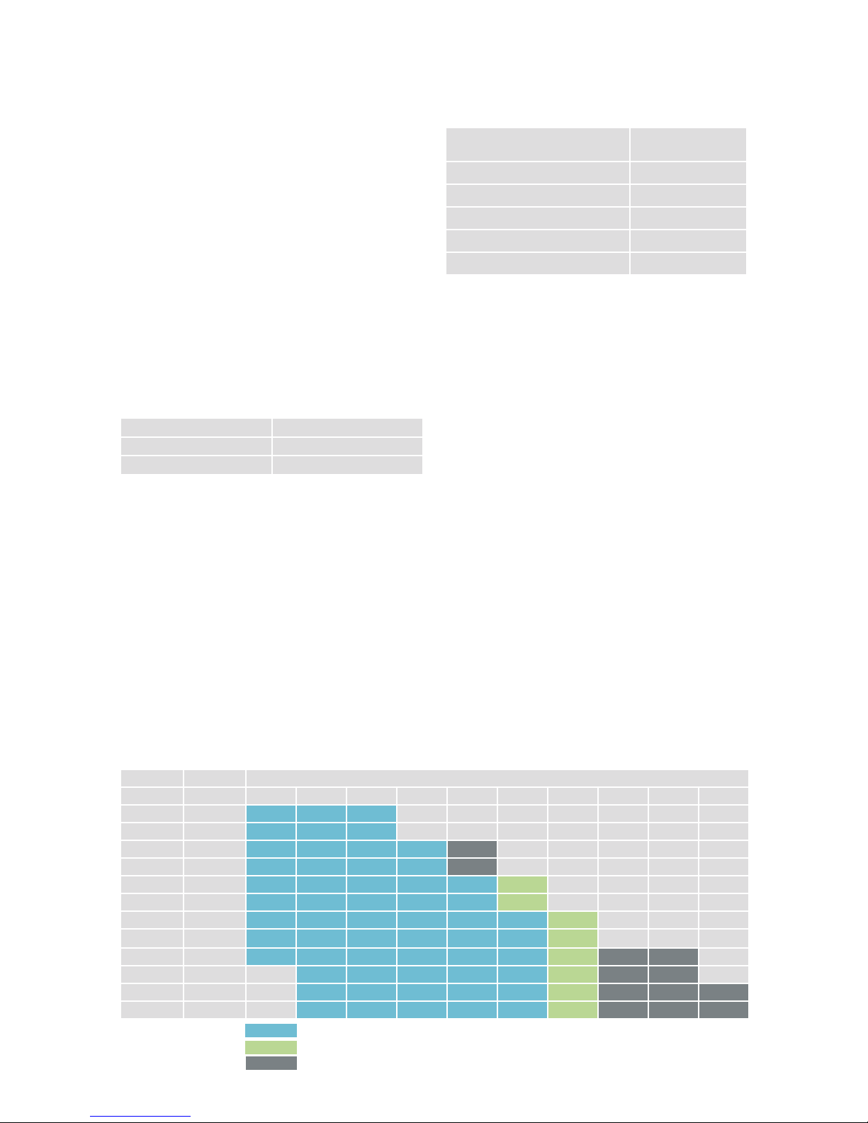
5.5.1 Selection of geotechnical dimensioning
method for steel piles
The geotechnical compressive strength of steel piles can
be determined according to PO-2016 in several ways,
whose applicability is shown in Table 15.
5.5.2 Stiness of a piled structure
The stiffness of a piled structure is taken into account
in building construction projects according to the
instructions of PO-2016 and in civil engineering projects
according to those of NCCI7. The correlation coefficients
presented in these instructions and the design values
based on them assume that the structures are not so-
called rigid structures.

17
5.5.3 Resistances determined by stress wave
analysis
Determining end-of-driving criterias by stress wave
analysis is the preferred method for driven RR75 to
RR320 piles in piling classes PTL1 and PTL2.
Sec. 11 of these instructions and Appendix 3 present end-
of-driving criterias for different pile driving equipments,
piles and pile lengths (10, 20 and 30 m) based on the
one-dimensional stress wave theory using the GRLWEAP
program. Correlation factor ξ5is 1.47 (1.40 x 1.05) according
to PO-2016 Part 1 Sections 4.5.2.4 and 4.5.2.6. The end-
of-driving tables present the targeted geotechnical
ultimate resistance at different piling class, design values
of geotechnical resistance Rdcorresponding to the
ultimate resistance, and end-of-driving criterias for each
pile driving equipment/pile combination. The design value
Rdis obtained as follows:
Rd= Rc/(ξ5xt)= Rc/(1.47 x 1.20) = Rc/1.764 (1)
The Rdvalues presented in the end-of-driving conditions
and Table 22 can be used directly in design for piling class
PTL1 and PTL2, and the geotechnical resistance of the pile
is ensured when the end-of-driving criterias are met.
In Table 22 the design values of geotechnical resistance for
PTL3 are calculated according to Formula (1). The design
values can be used as input values for design, and geo-
technical resistance must be ensured by dynamic load tests.
5.5.4 Resistances determined by dynamic load tests
Resistances determined by dynamic load tests are
suitable for friction and end-bearing piles at pile sizes
RR75 to RR1200 in all piling classes. Dynamic load tests
must always be used at building construction sites where
driven piles are used and the piling class is PTL3. In the
case of large diameter piles, dynamic load tests are
always recommended even with PTL2.
Correlation coefficients and related model coefficients
are presented in PO-2016. The dimensioning program
for RR and RD piles calculates correlation coefficients
automatically on the basis of input data.
Dimensioning based on dynamic load tests can in
principle be performed in two different ways.
1) The design value of geotechnical resistance Rdis
selected on the basis of piling class from Table 22, and
is used to calculate the minimum and average targets
for dynamic load tests.
2) The ultimate geotechnical resistance of the pile type
in question reliably achievable in the soil conditions of
the site is assessed considering the highest allowable
impact resistance of the piling class (Appendix 1),
and the design value of geotechnical compressive
resistance is calculated on the basis of this assessment
and dynamic load tests.
Table 15. Suitability of geotechnical dimensioning methods for dierent steel pile types.
Pile
static load test
dynamic load test
based on ground test results
end-of-driving criterias/
measurements based on pile
driving formulas
end-of-driving instructions
based on stress wave
analysis
based on the behaviour of
a corresponding foundation
RR small diameter piles/end-bearing piles PTL1–2 X XX X XX XXX X
RR small diameter piles/end-bearing piles PTL3 X XXX X XX XX X
RR large diameter piles/end-bearing piles - XXX X XX XX X
RR small diameter piles/friction piles XX XXX XX XX XX X
RR large diameter piles/friction piles - XXX XX XX XX X
CSG-RR piles/friction piles XXX - XX - X XX
Jacked RR-piles XXX X XX - - XX
RD piles X X XXX* X X X
Tension piles xxx x xx - x x
XXX = preferred method
XX = applicable
X = possible, applicability to be assessed case by case
- = technically infeasible or uneconomical
XXX* = RD piles feasible assuming that the bedrock surface has been reliably established or
that the bearing capacity of RD piles based on skin friction is determined by calculations

18
5.5.5 Resistances determined by pile driving
formulas
Pile driving formulas can be used in piling class PTL1 or PTL2,
for example, in situations where, according to the end-
of-driving table, the used pile driver is not able to mobilise
sufficient ultimate geotechnical resistance and geotechnical
resistance is ensured by a separate test loading hammer
without a dynamic load test. The pile driving formulas are used
according to PO-2016, Ch. 1, Sec. 4.5.2.5.
5.5.6 Resistances determined on the basis of ground
test results
Geotechnical resistance is determined on the basis of ground
test results according to PO-2016, Ch. 1, Sec. 4.5.2.3. It is
recommended that the so-called alternative method is
used in design, where a model factor of ≥1.6 is used for
end-bearing and friction piles and ≥1.95 for cohesion piles in
long-term loading and ≥1.40 in short-term loading.
As concerns steel piles, the capacity of both smooth and
grouted friction piles can be determined on the basis of
ground investigation results, but it is recommended that
the capacity is also determined by static or dynamic load
tests. This method is highly suitable for calculating the
geotechnical compressive strength of foundation piles of
lightweight noise barriers.
The point and shaft resistance of piles can be estimated
either on the basis of the angle of friction or cohesion of soil or
directly based on sounding resistance according to PO-2016.
5.5.6.1 Special features of the geotechnical resistance of
open ended steel pipe piles
In preliminary analyses of open ended steel piles with point
reinforcement ring (a steel collar over the shaft), external
shaft resistance can be estimated to decrease by 50 %
in a dense coarse-grained soil layer or moraine layer,
and 25 % in a loose layer compared to the table values
presented in PO-2016 or static capacity formulas. Point
resistance increases with increasing pile-point area.
If no plugging occurs in the pile, internal shaft resistance
can be assumed to be half of external shaft resistance in
preliminary analyses. However, the capacity consisting of
internal shaft resistance and point resistance of the area
of the steel cross-section of the pile must not exceed the
capacity of a plugged pile of corresponding size due to
point resistance.
5.5.6.2 Geotechnical resistance of grouted CSG-RR piles
bearing on a soil layer
The dimensioning geotechnical diameter of shaft grouted
piles (dd) may be larger than the diameter of the collar
(d0) used with the pile. The increase in diameter is caused
by the pressurising effect of grout with this installation
method, which makes the grout both displace and mix
with the soil layers surrounding the pile.
The dimensioning geotechnical diameter can be
determined, for example, by measurements on a test pile
or by using information on shaft grouted micropiles in
corresponding soil conditions. The magnitude of
the dimensioning diameter can be evaluated using
Formula 2.
dd = a ·d0 (2)
where ddis the dimensioning geotechnical diameter;
ais the coefficient that depends on soil type, grout
pressure, etc. and
d0is the diameter of the collar used with the pile in
question
The coefficient can vary with different soil types as follows:
clay a= 1.0
silt a= 1.0 to 1.1
sand, gravel a= 1.1 to 1.2
moraine a= 1.0 to 1.2
With shaft grouted CSG-RR piles the shaft resistance
factors of Table 16 can be used as shaft resistance
factor Kstanφa, and the dimensioning of point resistance
is the same as with non-grouted piles. Values based on
sounding resistance may also be used to evaluate shaft
and point resistance, see PO-2016, Ch. 1, Tables 4.6 and
4.8.
5.5.6.3 Geotechnical resistance of RD piles drilled into
bedrock
The point resistance of a pile bearing on solid Finnish
bedrock is usually not a dimensioning factor, but
resistance is determined on the basis of the structural
resistance of the pile.
The tip of the pile is assumed to bear on bedrock when
both drilling observations and geotechnical investigations
confirm it.
Table 16. Shaft resistance factor Kstanφafor grouted piles in coarse-grained soil types.
Internal angle of friction of soil [o]
28 30 32 34 36 38 40 42
Kstanφa1.2 1.3 1.5 1.7 2.1 2.5 2.9 3.4

19
The quality of the rock contact of RD piles is ensured by
drilling the pile at least 3.ddeep, but no less than 0.5 m,
in solid bedrock. With larger drilled piles, over 300 mm in
diameter, 3.dcan be considered a safe drilling depth into
bedrock, but drilling the pile more than 1.5 m into bedrock
is usually not practical in Finland. In bridge projects of
the Finnish Transport Agency, the dimensioning and
implementation instructions of the publication ”Sillan
geotekninen suunnittelu” (Geotechnical design of a
bridge) for joint stiffness and drilling depth of RD piles into
bedrock are followed.
Drilling piles more than 1.5 m into solid bedrock may be
appropriate, for instance, when excavation or blasting
takes place after installation of piles in their immediate
vicinity. Three metres below the excavation level can
be considered a safe target level for piles in bedrock in
the case of conventional blasting. If the target level is
3 metres higher than above, the properties of the rock
and its breaking during blasting must be considered
carefully in the planning and execution of the work.
The rock contact of the tip of RD piles installed by the
concentric drilling method remains after rock penetration.
When the RD pile is filled completely or partly with
grouting mortar or concrete, loads from the pile to the
bedrock are transmitted across the entire area of the pile
bottom.
In fragmented bedrock piles are drilled deeper all the way
to solid bedrock, or the rock is grouted or geotechnical
resistance is evaluated case by case. Geotechnical
resistance can be determined by calculations if the
strength properties of the fragmented rock can be
estimated or determined reliably enough.
The contact of RD piles with rock after the end of drilling
is ensured by applying ”final or control blows” by a drill
hammer to the top of each pile.
The shaft resistance of a pile in bedrock can be made
use of in geotechnical dimensioning of RD piles. It can
be used, for example, if the pile bears on a weakness
zone in bedrock or is subject to tensile loads. With
vertically loaded RD piles dimensioned to be shaft-
bearing, the distance between the hole in the rock and
the reinforcement must be at least 15 mm. The shaft
resistance of RD piles in bedrock can be utilised, for
example, by drilling the RD pile first to the surface of
bedrock, and then continuing to drill with a smaller
drill bit deeper into bedrock. The drill hole is flushed
clean, filled with concrete, grouting mortar or injection
grout, and then a steel pipe equipped with centralisers,
at least 30 mm smaller in outer diameter than the
diameter of the hole in the bedrock, is installed in
the hole. The bond stress values between steel and
grouting mortar and grouting mortar and rock are
presented in PO2016, Ch. 1, Table 4.9.
5.5.7 Resistances determined by static load tests
Static load tests are used mainly in the geotechnical
dimensioning of shaft grouted CSG-RR piles, jacked RR-
piles and tension piles. In rapid load tests, the correlation
coefficients of PO-2016, Ch. 1, Tables 4.1 and 4.2 are
multiplied by 1.2. Even in rapid loading, the displacement
during the load step of the highest load must be
monitored for at least 5 minutes. The rate of settlement
during the last 5 minutes of the monitoring period must be
less than half of that of the first 5 minutes.
5.6 Geotechnical dimensioning of tension piles
The geotechnical dimensioning of tension piles is carried
out according to PO-2016, Sec. 4.5.3.
If mechanical splices are used in pile splicing, the
design value of tensile strength must be limited to that
of the splice, which in the case of driven RR piles is
15% of compressive strength and with RD piles 50% of
compressive strength.
In the case of RD piles with conventional casing shoes
and ring bits, the grouting mortar or concrete possibly
penetrating between the hole in the bedrock and the pile
pipe after concreting cannot be taken into account in
dimensioning without a closer analysis.
If anchors are used with the piles, the entire tensile force
on the pile must be taken by the anchor.
5.7 Structural resistance
5.7.1 Resistance of RR piles during installation
The structural resistance of driven piles in dierent piling
classes must be limited according to PO-2016 as follows:
Table 17. Maximum characteristic value of geotechnical
resistance for driven piles and maximum centric impact
force.
Maximum allowed centric
impact force causing
compression stress during
installation*
Nimpact (-)
Maximum characteristic
value of resistance
Rc;max
≤0.9 ×fyk ×As
PTL3: Rc;max ≤Nimpact(-)
PTL2: Rc;max ≤0.8 ×Nimpact(-)
PTL1: Rc;max≤0.6 ×Nimpact(-)
*when stresses/impact force are measured during driving,
the above stress level cannot be exceeded by more than 20 %
(impact stress ≤1.08 x fy) (EN 12699).

20
Appendix 1 presents the maximum resistance Rc;max values
during driving for all RR piles in various piling classes.
5.7.2 Structural resistance during service
The structural resistance of a pile is verified in terms of
both pile structure and soil failure according to Piling
Manual PO-2016.
The compressive resistance of piles against buckling
is determined in conditions where piles may buckle due to
the lack of sufficient lateral support. The lateral support
of soil is usually not utilised if the shear strength of the
organic soil layer around the pile is less than
5 kN/m2. Then, the pile is dimensioned as a column and
the unbraced length is determined on the basis of soil
conditions and the structural joint between the upper and
lower ends of the pile.
The ultimate buckling resistance of an axially loaded
pile is calculated by the method presented in PO-2016,
Sec. 4.7.5, where the pile is assumed to be surrounded by
a fine-grained soil layer over its entire unbraced length.
A constant spring value is used for subsoil along the entire
unbraced length in dimensioning. In a coarse-grained soil
layer, the above calculation method can be utilised by
estimating the unbraced length and using, for example,
a conservative spring value for frictional soil along the
entire unbraced length.
Initial deflection after installation prior to loading is taken
into account in buckling analyses of axially loaded piles.
At the design stage, values Lcr/200 to Lcr/800 of the
table can be used as the value of the geometric initial
deflection of a pile. The values of the greater divisor of
the table, that is, the larger radius of curvature, can be
used when the installation conditions are expected to be
easy, and the smaller radius of curvature values when the
installation conditions are expected to be difficult. The
value recommended for a spliced pile is used only if the
splice is located along the unbraced length Lcr in a soft soil
layer.
Table 18. Initial deflection values used with SSAB’s steel
piles in design.
Unspliced
pile
Spliced
pile
Initial deflection g[m],
RR and RRs piles and
CSG-RR piles
Lcr/300–Lcr/600 Lcr/200–Lcr/400
Initial deflection g[m],
RD and RDs piles Lcr/500–Lcr/800 Lcr/300–Lcr/600
If the straightness of the pile is measured, for example,
with a torch or an inclinometer, the radius of curvature
determined on the basis of the measurements can be
used in design. The dimensioning program for RR and
RD piles can be used for easy calculation of the radius
of curvature used in the dimensioning of a pile. The
calculated radius of curvature depends on the critical
unbraced length, which, in turn, depends on the stiffness
of the pile, the modulus of subgrade reaction and
effective width of the pile.
According to PO-2016 and in the dimensioning program
for RR and RD piles, the partial safety factor for strength
of soil is applied to the ultimate stress limit of lateral
resistance at the end of the calculation.
Steel cross-section classes are taken into account according
to EN 1993-1-1 and EN 1994-1-1 in the calculation of the
ultimate bending moment capacity of the pile structure.
With CSG-RR piles, the effective width of the pile is based
on the width of the collar. An external grout mantle is not
taken into account in determining the ultimate bending
moment capacity of the structure.
If a pile is loaded by an external bending moment and/or
a torque and/or a shear force, besides a normal force, the
pile or the part of it subject to the stress in question must
be dimensioned for the combined stresses.
Secs. 5.12 and 5.13 of these instructions present pre-
calculated dimensioning values for structural resistance
at corrosion allowances of 1.2 mm and 2.0 mm.
5.7.3 Corrosion
The average corrosion rate of unprotected steel piles in
normal conditions underground can be assumed to be at
least 1.2 mm in a hundred years in the case of the external
surfaces susceptible to corrosion. Corrosion of the inner
surfaces of steel pipe piles with a closed lower end or ones
filled with concrete can be ignored.
Corrosion rate depends on ambient conditions.
Table 19 presents some indicative values for average
surface corrosion of steel piles in some conditions. The
recommendations of the table were originally presented in
standard EN 1993-5.
Alternatively, the corrosion rate of piles not filled with
concrete can in certain normal conditions be estimated on
the basis of the values presented in Table 20. The table is
based on statistical processing of corrosion observations,
where the risk related to conditions is taken into account
by using the so-called pit corrosion factor and possible
internal corrosion by theoretical calculations.
If soil conditions prove unusual, Table 19 can be applied
where applicable.
This manual suits for next models
76
Table of contents
Other Ssab Construction Equipment manuals


