!
1
1
T001_W
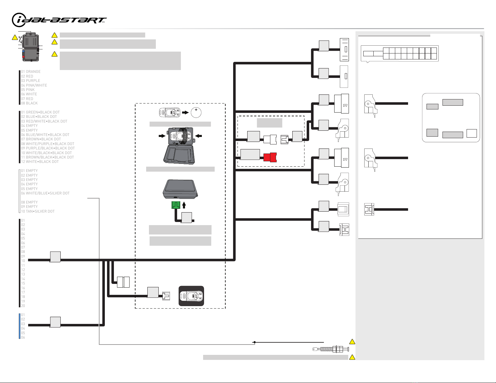
CUT LOOP FOR AUTOMATIC TRANSMISSION ONLYCUT LOOP FOR AUTOMATIC TRANSMISSION ONLY
2
TWO KEYS ARE REQUIRED FOR THIS INSTALLATION.
ONE KEY WILL REMAIN PERMANENTLY IN THE VEHICLE.
THE OTHER KEY WILL BE USED FOR THE PROGRAMMING
PROCEDURE.
IT WILL THEN BE RETURNED TO THE OWNER.
TWO KEYS ARE REQUIRED FOR THIS INSTALLATION.
ONE KEY WILL REMAIN PERMANENTLY IN THE VEHICLE.
THE OTHER KEY WILL BE USED FOR THE PROGRAMMING
PROCEDURE.
IT WILL THEN BE RETURNED TO THE OWNER.
13 GREEN/RED - PTS 2 (-) OUTPUT13 GREEN/RED - PTS 2 (-) OUTPUT
14 ORANGE/WHITE14 ORANGE/WHITE
HARDWIRE / WIRING DIAGRAM - 1 OF 1
M5
M4
M2
M3
04 GREEN/WHITE•BLACK DOT04 GREEN/WHITE•BLACK DOT
03 BROWN/RED - CANH 103 BROWN/RED - CANH 1
04 BROWN/YELLOW - CANL 104 BROWN/YELLOW - CANL 1
IGNITION (+) BLACK/PURPLE - 17
PTS 1 (-) WHITE/RED OR WHITE - 10
REAR BCM, LEFT SIDE OF TRUNK (A)
12V (+) RED/YELLOW - 16
CANL (DATA) ORANGE/BROWN - 01
CANH (DATA) GREEN - 02
PTS 3 (-) YELLOW/GREEN - 26
PTS 2 (-) BROWN/RED - 25
BRAKE (+) BLACK - 12
GROUND (-) BROWN - 15
06 BLUE/WHITE•BLACK DOT06 BLUE/WHITE•BLACK DOT
08 WHITE/PURPLE•BLACK DOT
01 GREEN•BLACK DOT01 GREEN•BLACK DOT
02 BLUE•BLACK DOT02 BLUE•BLACK DOT
03 RED/WHITE•BLACK DOT03 RED/WHITE•BLACK DOT
05 GREEN/BLACK•BLACK DOT05 GREEN/BLACK•BLACK DOT
09 PURPLE/BLACK•BLACK DOT09 PURPLE/BLACK•BLACK DOT
11 BROWN/BLACK•BLACK DOT11 BROWN/BLACK•BLACK DOT
12 WHITE•BLACK DOT12 WHITE•BLACK DOT
01 BROWN•SILVER DOT01 BROWN•SILVER DOT
02 BLACK/WHITE•SILVER DOT02 BLACK/WHITE•SILVER DOT
03 PURPLE•SILVER DOT03 PURPLE•SILVER DOT
04 GREEN•SILVER DOT04 GREEN•SILVER DOT
05 PURPLE/WHITE•SILVER DOT05 PURPLE/WHITE•SILVER DOT
06 WHITE/BLUE•SILVER DOT06 WHITE/BLUE•SILVER DOT
08 BLUE•SILVER DOT08 BLUE•SILVER DOT
09 GRAY/BLACK•SILVER DOT09 GRAY/BLACK•SILVER DOT
06 BLUE/YELLOW06 BLUE/YELLOW
11 GRAY/RED - PTS 3 (-) OUTPUT11 GRAY/RED - PTS 3 (-) OUTPUT
12 GRAY/YELLOW12 GRAY/YELLOW
16 ORANGE/BLACK - PTS 1 (-) OUTPUT16 ORANGE/BLACK - PTS 1 (-) OUTPUT
17 PINK - IGNITION (+) IN/OUT17 PINK - IGNITION (+) IN/OUT
18 PURPLE - STARTER (+) OUTPUT18 PURPLE - STARTER (+) OUTPUT
19 RED - 12V (+) INPUT19 RED - 12V (+) INPUT
20 BLACK - GROUND (-)20 BLACK - GROUND (-)
01 GRAY/BLACK•BLUE DOT01 GRAY/BLACK•BLUE DOT
02 WHITE/BLACK•BLUE DOT - IMMOBILIZER (DATA) VEHICLE SIDE02 WHITE/BLACK•BLUE DOT - IMMOBILIZER (DATA) VEHICLE SIDE
03 GRAY/RED•BLUE DOT03 GRAY/RED•BLUE DOT
04 WHITE/RED•BLUE DOT - IMMOBILIZER (DATA) CONNECTOR SIDE04 WHITE/RED•BLUE DOT - IMMOBILIZER (DATA) CONNECTOR SIDE
05 GRAY•BLUE DOT05 GRAY•BLUE DOT
06 WHITE•BLUE DOT - IMMOBILIZER (DATA)06 WHITE•BLUE DOT - IMMOBILIZER (DATA)
07 GRAY•SILVER DOT - HOOD (-) INPUT
07 GRAY•SILVER DOT - HOOD (-) INPUT
10 WHITE/BLACK•BLACK DOT - HORN (-) OUTPUT10 WHITE/BLACK•BLACK DOT - HORN (-) OUTPUT
HORN (-)
HOOD SWITCH
INSTALL THE SUPPLIED HOOD SWITCH IF THE VEHICLE IS NOT EQUIPPED WITH ONE.
3: T17N TAN
IMMOBILIZER (DATA) YELLOW - 01
PANIC
14
17 1516
7
13
6
12
5
11
4
10
3
9
2
8
1
REMOVE BATTERY
20 LOOPS (24 AWG)
AROUND KEYFOB
1
3
4: T20N BLACK
1: T32H - LTBLUE/WHITE
2: T32G - BLACK/WHITE
18
9
17
8
16
7
15
6
14 13 12
3
11 10
1
20 19
245
4
2
1011
1213
1415
16
1718192021222324
2526272829303132
1
23456789
1011
1213
1415
16
17181920212223242526272829303132
123456789
M1
!
M3
M1
M2 M5
M4
PAGE 6 OF 13
U.S. Patent No. 8,856,780 CA 2759622
Automotive Data Solutions Inc. © 2022 www.idatalink.com
RSD-AUD1-[CMHCXA0]-EN
2022 Audi A4 PTS Automatic
Doc No.: A5EB220 - 20220819_094230