ADSI i-TECH 230 User manual


Limited Warranty Agreement ............................................................ 1
Service Policy .................................................................................... 1
Technical Su ort .............................................................................. 2
Installation ......................................................................................... 2
SET-UP .......................................................................................................... 2
i-TECH Cutter Stand .................................................................................... 3
Com uter Connection .................................................................................... 3
System Interfacing .............................................................................................. 3
Loading Allen i-TECH Software ................................................................... 3
Windows 7, Vista, or Windows XP DirectCUT Driver ...................................... 3
Software U dates ............................................................................................... 3
Using Cutter ....................................................................................... 4
Install knife Blade in Holder .......................................................................... 4
Install Blade Holder in Machine .................................................................... 4
Load Media .................................................................................................... 4
Setting Force / Velocity ................................................................................. 4
Sending Job .................................................................................................... 4
Illustrator / CorelDraw ....................................................................................... 4
AllenCAD .......................................................................................................... 5
Omega Com oser ............................................................................................... 5
Signlab ............................................................................................................... 5
Flexisign ............................................................................................................. 5
O eration of the i-TECH SmartMarkTM System ............................. 5
O tional SmartMarkTM Sensor ................................................................... 5
Setting U Your Label Job ............................................................................ 5
Ex lanation of SmartMarkTM ....................................................................... 6
Ty es of SmartMarkTM Scanning ................................................................ 6
Designing Labels ........................................................................................... 7
Planning Label ................................................................................................... 7
Using Adobe Suite Tools ................................................................................... 7
Using Corel Suite Tools ..................................................................................... 8
Lining u SmartMarkTM ................................................................................... 9
Sending file with Illustrator ................................................................................ 9
Sending file with CorelDraw .............................................................................................. 10
Find Origin Ty e ................................................................................................................ 10
Rotation ............................................................................................................................. 10
Cutting label ..................................................................................................... 10
Smart Mark Setu ........................................................................................ 10

Control Panel ................................................................................... 10
Remote Panel ................................................................................... 14
Remote Panel Functions .............................................................................. 15
Action menu ................................................................................................. 15
Send HPGL File .............................................................................................. 15
Save Settings from Cutter to File, Load Settings from File To Cutter .............. 15
Save Calibration/Restore Calibration ............................................................... 15
U load Firmware .............................................................................................. 15
Action Menu (Advanced O tions) ............................................................... 15
O en Com Port ................................................................................................ 15
Close Com Port ................................................................................................ 15
Cancel, Continue, Pause ................................................................................... 15
Save NVROM and Restore NVROM .............................................................. 15
Setu Menu .................................................................................................. 16
Main Menu ....................................................................................................... 16
State Tab ............................................................................................................................ 16
State Tab (Advance O tions) .............................................................................................. 16
Pen Control Tab .................................................................................................................. 17
Rubber Tab ......................................................................................................................... 17
Rubber Tab - (Advanced O tions) ..................................................................................... 17
Line Sensor ....................................................................................................... 18
Line Sensor (Advanced O tions) ........................................................................................ 19
Skew Tab ............................................................................................................................ 19
Skew Tab (Advanced O tions) ........................................................................................... 20
Scale Tab ............................................................................................................................ 20
Scale Tab (Advanced O tions) .......................................................................................... 20
Settings Menu ................................................................................................... 21
Settings Menu (Advanced O tions) .................................................................. 22
O tions Menu .................................................................................................. 23
O tions menu (Advance O tions) .................................................................... 24
Dynamic Force Adjust (Advanced O tion) ...................................................... 24
Diagnostics ................................................................................................... 25
Window ........................................................................................................ 25
Hel .............................................................................................................. 25
Joy Stick ....................................................................................................... 25
Installing Knife Blades .................................................................... 26
Calibration ...................................................................................... 27
Maintenance ..................................................................................... 27
Cleaning ....................................................................................................... 27
Pinch Wheel Maintenance ........................................................................... 28
Mechanical Adjustments .............................................................................. 28
Belt Tension ..................................................................................................... 28

Diagnostics ...................................................................................... 29
Diagnostic O eration ................................................................................... 29
Control anel o eration .................................................................................... 29
Remote anel o eration .................................................................................... 30
Setu Diagnostics ........................................................................................ 30
Calibrate 07, Calibrate To Printer and SmartMark Setu ............................. 30
Calibration Square Plot .................................................................................... 30
Default Calibration 08 ..................................................................................... 30
FO Out ut ........................................................................................................ 30
Customer Diagnostics ................................................................................. 30
Button Diagnostic 31 ........................................................................................ 31
Confidence Test 02 ........................................................................................... 31
Flag Adjust 34 ................................................................................................. 31
Flag Setu - Z Axis 58 ..................................................................................... 32
Front Pa er Sensor 26 / Rear Pa er Sensor 27 ................................................. 32
LED and Hex Dis lay 29 ................................................................................. 32
Line Sensor 21 .................................................................................................. 32
Lift/Lower Continuous 37 ................................................................................ 32
Lift/Lower Demand 38 ..................................................................................... 32
PWM Am lifier Status .................................................................................... 32
Read Calibration Constants .............................................................................. 32
Reed Switch 24 ................................................................................................. 33
Front Panel Only Diagnostics ...................................................................... 33
Dis lay Last Error 15 ....................................................................................... 33
Factory Defaults 43 .......................................................................................... 33
Set Model Number 03 ...................................................................................... 33
Set Static/DHCP IP Address 04 ........................................................................ 33
Trouble Shooting ............................................................................. 34
Error Codes ...................................................................................... 39
A endix A Installation And Assembly Instructions ...................... 39
A endix B SmartMarkTM Setu ................................................... 39
A endix C Loading ........................................................................ 39
A endix D Cart Assembly Instructions ......................................... 39
A endix E Radio and Television Interference ............................. 40
A endix F Model i-536 Addendum ............................................... 40
A endix G Model i-536 Adjustable Parameters ............................ 40
A endix H Hot Ti Instructions .................................................... 40
A endix I Tem late Maker Su lement ........................................ 40

Limited Warranty Agreement
ALLEN DATAGRAPH i-TECH cutters are warranted to be free of defects in both materials and
workmanshi . Should any art of this equi ment be defective, it will be re aired or re laced, at the
o tion of the manufacturer, at no charge for arts or factory labor for a eriod of two (2) years from
the date of installation. All warranty services are erformed at the Allen Datagra h factory.
Re lacement arts not installed at the factory will be billed to the customer at regular rices and
credit will be issued when the defective arts are returned. The customer is res onsible for freight
on warranty arts and re airs.
This warranty is void if:
1. The equi ment has been damaged by negligence, accident or mishandling, or has not been
o erated in accordance with the rocedures described in the o erating instructions;
or:
2. The equi ment has been altered or re aired by other than an a roved service station or
factory service center, or ada tations or accessories have been attached to the equi ment that shall
have adversely affected the erformance, safety, or reliability of the equi ment.
NO OTHER WARRANTY, EXPRESSED OR IMPLIED, APPLIES to the equi ment. Allen
Datagra h does not assume any res onsibility for consequential damages occasioned by the
equi ment, or inconvenience or interru tion in o eration.
In case of unsatisfactory o eration, Allen Datagra h or its Dealer should be notified immediately.
Service P licy
When making your decision as to which way to roceed with the re air of your ADSI equi ment,
lease bear in mind that troubleshooting of com lex electronic equi ment can sometimes take
multi le attem ts to re air an issue. It is always best from a manufacturer’s oint of view to have
the com lete system in-house to insure that the machine is in erfect working order when you
receive it back from us. Please consider all as ects before making your decision as to which o tion
to utilize. We make every attem t to minimize downtime for our customers, and sometimes the
best way is to have the machine in our facility.
WARRANTY SERVICE:
Option 1) ATTEMPT TO REPAIR OVER THE PHONE: We do not normally encourage
customers to re air ADSI equi ment on their own. Sometimes, in the interest of minimizing
downtime, and under the guidance of ADSI service ersonnel, we will try and re air an issue over
the hone. This may require that you shi us arts from your machine as er the warranty statement
found in the front of your ADSI user’s manual, or for ADSI to shi arts to you for installation.
NOTE: Any replacement parts shipped to you require that you ship the old parts back to ADSI
unless pre iously appro ed. Failure to do so will result in the parts being charged to you. All re-
turned parts require a Return Material Authorization Number (RMA), which must be obtained
from an ADSI representati e prior to return shipment.
All hone-su orted re airs are handled on a er-case basis, and at the discretion of ADSI Service
ersonnel.
Option 2) SERVICE AT OUR FACILITY: Shi the machine to ADSI for re air under the terms
of the written warranty statement found in the user’s manual. Parts and labor are rovided at no
charge to the customer, but the customer is res onsible for freight to and from Allen Datagra h.
1

Option 3) ON-SITE SERVICE: ADSI will, on occasion, for the cost of all airfare and travel ex-
enses, send an ADSI technician to your facility to re air in-warranty equi ment. Parts and labor
are rovided at no cost to the customer. Bear in mind that on-site service is sometimes not the most
cost or time-effective way to resolve issues and may result in longer down time due to scheduling
of airfare, etc.
NON-WARRANTY SERVICE:
In most out of warranty re air scenarios, we require customers to send the machine to us for
re air. This is the best way to insure that the machine you get back will be fully functional u on
arrival at your facility.
In some cases we may determine that the roblem is a sim le one, such as a belt, and decide the
issue may be resolved without shi ing the machine in. In this case, you can decide to re air the
machine yourself. This will require us to shi arts to you for installation. Parts will be charged at
retail ricing rior to shi ing. Bear in mind that this method may ultimately increase downtime
and/or may take more than one attem t to resolve the issue. If the issue cannot be resolved in a
timely manner, the machine will be required to be shi ed to ADSI for service.
NOTE:A credit card number is required at the time of shipment of any parts. In a warranty sit-
uation, the card will not be charged with the exception of shipping charges, as long as parts are
returned to ADSI in a timely manner. Non-warranty parts are required to be paid in full prior to
shipment.
Technical Supp rt
U to 4 hours of call in technical su ort is available at no charge during the warranty eriod.
Technical su ort is available during business hours based on Eastern Time Monday thru Friday.
Technical su ort outside the limits stated will be billed at current rates.
For Technical su ort call: 603-216-6344
There are many online documents available to hel you to use the Cutter at our technical su ort
age at htt ://www.allendatagra h.com.
Installati n
SET-UP
Some Allen Datagra h roducts require s ecialized installation in order for the limited warranty to
remain in effect, ask your dealer or contact technical su ort at Allen Datagra h for details.
Un ack all accessories and the unit. See installation and assembly instructions in A endix A.
P wer C nnecti n
Im ortant Note: Use of a HIGH QUALITY surge rotector or uninterru tible ower su ly is
REQUIRED by Allen Datagra h Systems. Failure to do so could affect your warranty coverage if a
roblem arises due to im ro er ower connection.
CAUTION: The ower cord is a three-conductor cable that incor orates a safety (earth) ground
connection. For the machine to o erate safely and correctly, the ower cord must be lugged into
an outlet that has an earth ground contact. Never lug the ower cord into a two- rong outlet by
using a 3=2 cord ada ter.
CAUTION: Never allow roll or sheet goods to rub on the ower cord because the material can cut
the cord causing an electrical fire hazard!
Allen Products exce t hot ti can be configured to o erate from any of the following ower
sources:
2

100-240 VAC / 47-63 Hz 250 watts
Hot ti is: 100-132 VAC / 47-63 Hz or 180-240 VAC / 47-63 Hz 300 watts
i-TECH Cutter Stand
The i-TECH CUTTER comes equi ed with a deluxe stand. Assembly instructions for the stand
are ackaged inside the stand box that arrived with your cutter.
N te: The material rollers and associated brackets are ackaged inside the cutter box, under the
ackaging foam. It is necessary to remove the foam in order remove the arts.
C mputer C nnecti n
System Interfacing
All Allen Datagra h roducts utilize either USB (universal serial bus) interface or Ethernet
connection. Connection from PC to cutter is either by USB or Ethernet. If you want to read about
using the Ethernet ort for the cutter see the document Website Co y / CD Co y.
The Cutter comes with a software installation CD that walks you through the installation of the
software on the com uter you are using. Do not lug any cables or ower cord until asked to do so
by the installation cd.
If you lug in the usb before the driver is installed the usb driver may not be installed correctly.
See "usb driver re air" if you did this before you read the instructions. htt ://adsi-
usa.com/techsu ort/cutterdriver.html / CD Co y.
If you do not have the CD you may download the cutter driver and install it from this age.
Choose latest version. htt ://adsi-usa.com/techsu ort/cutterdriver.html. Then download and
install the remote anel rogram from this age:
htt ://adsi-usa.com/techsu ort/i-TECHfirmware.html. If you are using AllenCAD you may
download latest version from: htt ://adsi-usa.com/techsu ort/AllenCAD.html. To download
other Technical su ort bulletins go to htt ://adsi-usa.com/ click on tech su ort, then online
documents, Find your cutter, cutter driver, or AllenCAD on the list shown and click on it.
L ading Allen i-TECH S ftware
The Firmware Utility CD installs:
1. The Remote Panel Utility rogram for managing machine settings.
2. A current revision of firmware.
"Firmware" is software that controls the machine functions. The
firmware on this disk is pro ided for update purposes only and
should not be installed on new machines.
3. Manual and sam le jobs.
4. Cutter driver for Windows 7, Vista, or Window XP.
Wind ws 7, Vista, r Wind ws XP DirectCUT Driver
This rinter driver has been tested with CorelDRAW (version 10-x5), Adobe Illustrator (version
10-cs5), Flexisign, Inksca e, and PowerCAD. It should work with any rogram that sends vectors
rather than bitma s to the rinter. Allows cutting directly from windows gra hics rograms
without requiring additional software urchases. N te: Driver requires ownershi of Allen
Datagra h Equi ment to use. Requires: Windows 7, Vista or Windows XP.
S ftware Updates
Software u dates after the roduct shi s will be available on the tech su ort section of the
htt ://allendatagra h.com web site.
3

To u date to a later version of software when recommended to do so by the tech su ort de art-
ment, go to the web site. Click on tech su ort, then online documents.
Select your cutter ty e, AllenCAD or Cutter driver from list of selections.
Find the software u date and click on it to download the setu rogram from the web site.
Installation instructions for the software are on the same age as the software.
Using Cutter
Install knife Blade in H lder
Remove knife blade from ackaging. Remove lastic ca . Dro it oint out into hole in black las-
tic ca of knife holder. The knife holder looks like a silver bullet.
Install Blade H lder in Machine
Place the knife holder into carriage so that ring sits flush with holder to
and blade almost touches media. Tighten thumb screw.
L ad Media
Load media using rocedures described in A endix C.
Setting F rce / Vel city
The cutter is shi ed with ower u setting suitable for the ty e of material
ex ected based on the model ordered. You should slower s eeds/accelera-
tions for heavier material. Start with force = 20 (use force u /down buttons)
and velocity = 66% (use velocity u /down buttons). Press test cut button.
This draws the test cut. Use joy stick arrows to move carriage away from
cut area. If you cut through backer, reduce force. If you cannot weed me-
dia increase force. If material sli s between grit roller and inch wheels use
slower accelerations. S ring ressure can also be changed by using alter-
nate s rings shi ed in the accessories. See Web Site Co y or CD Co y.
Sending J b
Summary
1. Insure lastic groove filler is in for cutting and removed for ouncing.
2. Install knife blade in knife holder.
3. Insure blade is out from de th guide.
4. Load material (A endix C Loading).
5. Install knife assembly.
6. Set machine to CUT MODE.
7. Perform cut test attern.
8. Adjust force, offset and de th guide.
9. Joy stick to where you what lower left corner of job to be using arrow buttons around
select button.
CAUTION: To avoid personal injury, keep hands, hair, clothing and jewelry away from
the cutter's moving parts at all times.
Illustrat r / C relDraw
Select on layer in layer menu or object manager that contains information you want to cut.
From Illustrator or CorelDraw click on File -> Allen DirectCut.
Select cutter driver in dro down between Pro erties and Cut button.
Click on Cut.
4

AllenCAD
Click Tile and rint. Select objects and ress enter key.
Click ok on o tions age
Select cutter driver in dro down between Pro erties and Cut button.
Click on Cut.
Omega C mp ser
See Web Site Co y / CD Co y
Signlab
For cutters using built in drivers you need to know the com ort cutter is attached to:
Click on start -> right click on my com uter -> ro erties
Click on hardware/device manager or device manager
Click on icon in front of orts com and l t and find com ort for Allen Datagra h equi ment.
Close device manager.
Click on file -> install cutting device
Select Allen Datagra h and click on next
Click on scissors on left hand control bar, click on (dot, dot, dot) ... next device window, select ort
tab, select ort number found above, click ok, then click scissors to send lot.
Flexisign
For cutters using built in drivers you need to know the com ort cutter is attached to:
Click on start -> right click on my com uter -> ro erties
click on hardware/device manager or device manager
click on icon in front of orts com and l t and find com ort for Allen Datagra h equi ment.
Click on (cut / lot) set u ort using Web Site Co y / CD Co y. Click send.
Operati n f the i-TECH SmartMarkTM System
Opti nal SmartMarkTM Sens r
The SmartMarkTM o tion that is available for Allen i-TECH cutters is an o tical registration system
that allows cutting of re- rinted gra hics. The SmatMark system has the ca ability of recognizing
u to three registration marks, and adjusting for scale and skew discre ancies the may occur.
The SmartMarkTM o tion consists of a eye sensor that is mounted to the cutting head.
The SmartMarkTM sensor recognizes changes in contrast from the background media to the rinted
mark. The “sensitivity” of the sensor must be set in order for the system to recognize the contrast
reliably and be able to cut accurately.
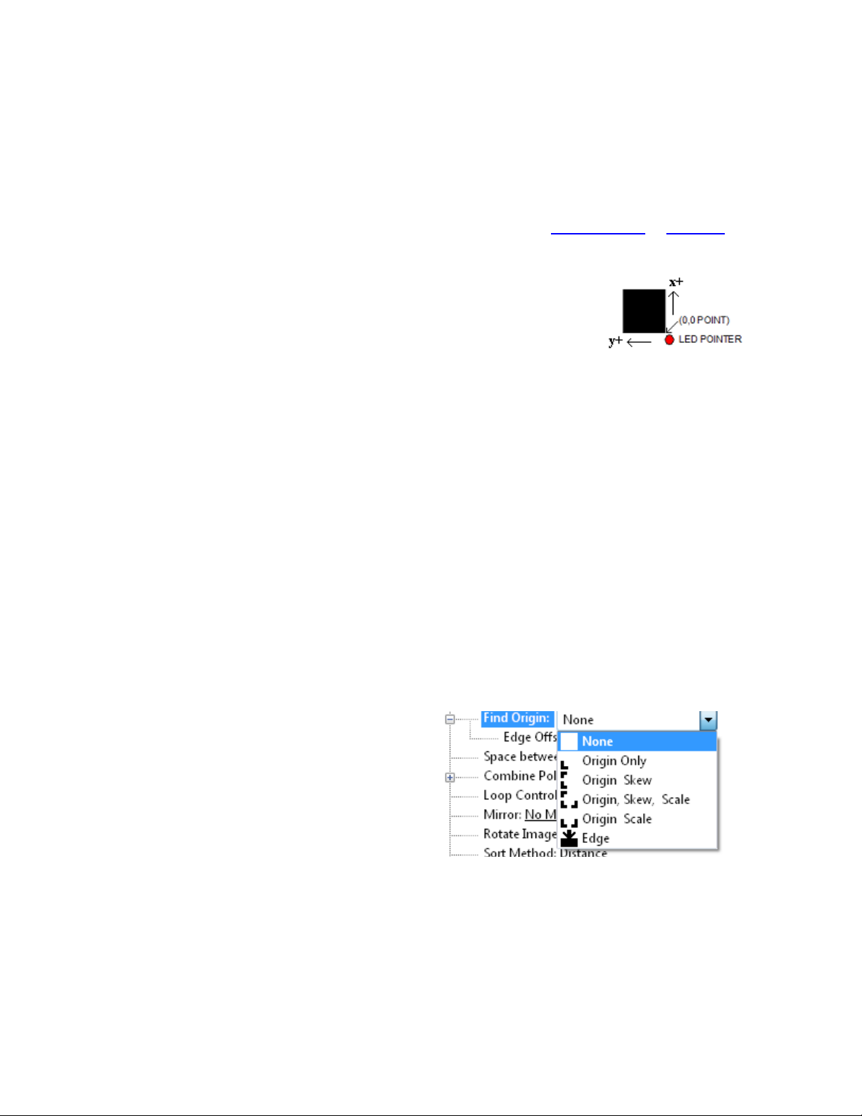
Setting Up Y ur Label J b
The target should be a black rectangle on white media or a
contrasting color to background. See colors in Web Site Co y
or CD Co y. The recommended Mark Size is 0.5 inch (12
mm). When using the SmartmarkTM on a cutter you normally
need at least two marks as it is difficult to get media loaded
straight and rinters to rint the correct size rinted in the x
axis of the rinter. The sensor relies on reading the change in
intensity of the reflection of the red LED ointer. When rint-
ing rocess colors on white media the best color for a target is
usually black. Certain s ot colors are difficult. For exam le
5
silver s ot on white, while to the eye there is contrast the reflectivity of the two is sometimes nearly
the same. If there is trouble with certain materials detecting the target you can rint the target in a
yellow or white field. The size of the yellow field should be larger than the scan length. (N te: in
order to get an accurate scan no other rinted marks may a ear in the yellow scan area. The rint-
er color alignment marks can a ear on the inside edge of the target or the other side of the media.)
The mark should be laced at least 0.5 inches (12 mm) from the edge of the media and the s acing
between frames should be at least 0.5 inch (12 mm). (Advanced usage: You can lace the target
closer to the edge of the material if you use inside out scanning. See Web Site Co y or CD Co y)
Explanati n f SmartMarkTM
The theory of o eration relies on the SmartMark sensor sending an analog
signal to the embedded com uter during a scan. The data is analyzed after
the scan to automatically create a threshold, find the edge of the target and
eliminate noise. The i-TECH scans the mark in both x and y directions and
calculates the intersection of the 2 scans. The i-TECH com uter then as-
signs that intersection as the 0,0 oint of the i-TECH coordinate system and matches that to the ori-
gin oint (minimum x, minimum y) of the HPGL cut file.
The i-TECH uses a s ecial HPGL command, FO, to start the registration mark sensing function. It
automatically re-registers the coordinate each time the FO HPGL command is received. As art of
the setu a “x move between jobs” is in ut via the rinter driver o tions which moves the sensor to
the a roximate osition of the next co y’s or next frame’s registration mark. The i-TECH ex ects
the target for the next frame to be within ½ the scan distance of the end of the frame.
The Red LED ointer must be manually ositioned with the joystick buttons at the a roximate 0,0
coordinate osition rior to sending the first job. The SmartMark system automatically re osi-
tions the sensor for subsequent co ies.
The ositioning rocess must be re eated if the joystick buttons are used. This is hel ful because it
allows the system to be reinitialized when needed.
Once the LED ointer is ositioned as shown, the SmartMark is ready to o erate and will scan
the registration mark when it receives a FO command in the job stream whether on the first co y or
on subsequent co ies. Since the FO command is embedded in the beginning of the cut file the scan
of the registration mark is erformed at the beginning of each co y or frame of labels and on subse-
quent co ies.
Types f SmartMarkTM Scanning
There are five ty es of SmartMarkTM scanning
available. They are shown in the image to the
right. The scan ty e is selected in the rinter driver
references.
Origin Skew, Origin Skew Scale, and Origin Scale
are the only ty es normally used on the cutter.
Origin Skew is used if the media is not necessarily
loaded straight. This scans the origin and the skew
mark and rotates the cut image to match the cut location at the two scanned locations. No scaling
of the cut image is erformed with Origin Skew scanning. If you cuts do not match in size from
the rint you either have to calibrate to rinter or use a different find origin ty e.
Origin Skew Scale does alignment at the origin, rotation and scaling in both x and y axes are re-
formed. This scan ty e requires that the sensor size arameter be correct so that cut image is same
size as rinted image.
Origin Scale does alignment at the origin, rotation and x-axis only scaling at the scale oint. It as-
sumes that the scaling in the y-axis is correct. If the rinter you are using has a x axis scaling error
6

you can normally correct this either in the rinter or you can use calibrate to rinter to get the cutter
to cut the same size as the rinter.
Origin Only is not normally used on cutter because its is hard to load media straight. Origin only
does a alignment with the visual sensor at the origin only.
Edge is not normally used on cutters. By selecting EDGE in the driver's rinting references
menu, the SmartMark sensor will detect the edge of the media instead of a registration mark, then
offset into the media by that amount and cut your blank labels.
Designing Labels
Planning Label
This tutorial will design a large contour cut of a hoto of a duck 26 x 10 inches (66 x 25 cm) label
for a rinter and an i-TECH cutter with SmartMarkTM with CorelDraw and Illustrator.
Now that we have work s ace lanned choose rogram to design your artwork. The image I used
was found on the internet at htt ://twilightearth.com/environment-archive-2/there-is-this-duck-that-
i-have-lunch-with/. Right click on the image and save it.
Using Ad be Suite T ls
O en hotosho and cro , magic wand and trim using laso tool to erase water near duck. No need
to be real accurate as we will create a cut line that trims the duck the way we want it to a ear.
save image as duck no water.j g
Use image -> size change height of image to 10. This makes the width about 22 inches.
save image as duck bigger image.j g
O en Illustrator and create a new document.
Change units to inches
Change width to 28 and height to 11
Click ok
Click on view -> rulers if rulers missing
Click on window -> layers if layer menu missing
Click on window -> color if color menu missing
Now create two layers. One called “dielines” and one called “ rint”. This is done from the layer
window. Click on new layer button. Then rename the layers as dielines and rint by double click-
ing on layer name, changing name and clicking on ok.
Next create the die lines. Click on the dielines layer on the layer window.
Create the die line for the target
Select dielines layer
Click on file lace. select duck bigger image.
7

Click on dro down arrow next to live trace button. select tracing o tions,
Select threshold of 254 and blur of 2 x, click on ok. Wait for trace to com lete. then click on ex-
and to move outline to dielines layer.
Click on object, ath, sim lify. Set curve recision to 10 and angle threshold to 10
Next click on the rint layer
Click on file -> lace and select duck bigger image.
From the ruler drag a guide line for left, right and bottom and lace the guide line close to the rint-
ed image.
Set fill to black and outline to null.
Note: if you have a stroke on the edge of the rinted target the rint and cut will not line u .
Select rectangle tool
Click near lower left intersection of the guide lines.
Select size 0.5, 0.5 for size, click ok
Zoom in to target only
Move target so that left and bottom of target are touching guide lines.
Re eat for lower right intersection lacing target so that right and bottom of target are touching
guide lines.
Lock the rint layer so you don't accidentally move it during editing of ath.
Clean u the ath using ath edit tools.
Add 1/2 inch rectangles for origin and scale on the dielines layer. The targets must be in same
lace on rint and dielines layers. These rectangles should have strokes and not filled.
This com leted label file is at this link Web Site Co y / CD Co y.
Use File -> save to save the file on your hard drive as big duck.ai. Using a color rinter rint im-
age..
To send dielines to cutter, click on dielines layer to select it and then click on
File -> Allen DirectCut.
Using C rel Suite T ls
O en Corel hoto aint and cro and trim using magic wand, freehand mask tool to erase water
near duck. No need to be real accurate as we will create a cut line that trims the duck the way we
want it to a ear.
Save image as duck no water corel.j g
Use image -> size change height of image to 10. This makes the width about 22 inches.
Save image as duck bigger image corel.j g
O en Corel Trace
O en duck bigger image corel.j g
Select advanced trace
Select max colors = 2, node ty e = smooth, minimum object size = 100, click on do trace
Save as duck bigger image corel.cmx
O en coreldraw and create a new document.
O en CorelDraw, Select -> tools -> o tions -> work s ace. Place a checkbox in front of Allen
Datagra h.
Next turn on 2 dockers: Select Window -> Dockers ->
Pro erties
and
8

Window -> Dockers -> Object Manager
Verify sna to guide lines is checked from the view menu.
This adds two control windows on the right side of the rogram
Change units to inches
Change width to 28 and height to 11
Click ok
Now create two layers. One called “dielines” and one called “ rint”. This is done from the layer
window. Click on new layer button. Then rename the layers as dielines and rint by double click-
ing on layer name, changing name and clicking on ok.
Next create the die lines. Click on the dielines layer on the layer window.
Create the die line for the target
Select dielines layer
Click on file im ort. select duck bigger image.cmx.
Next click on the rint layer
Click on file -> im ort and select duck bigger image.j g
From the ruler drag a guide line for left, right and bottom and lace the guide line close to the rint-
ed image.
Set Paint bucket = solid fill black and en nib outline to none.
Note: if not have a en nib outline on the edge of the rinted target the rint and cut will not line
u .
Select rectangle tool
Draw small rectangle of any size near where you want it.
Change size of rectangle to 0.5, 0.5 while rectangle is selected.
Zoom in to target only
Move target so that left and bottom of target are touching guide lines.
Re eat for lower right intersection lacing target so that right and bottom of target are touching
guide lines.
Lock the rint layer so you don't accidentally move it during editing of ath.
Set Paint bucket = no fill and outline to hairline and color black.
Add 1/2 rectangles for origin and scale on the dielines layer. They must be in same lace on rint
and dielines layers.
Clean u the ath using ath edit tools.
This com leted label file is at this link Web Site Co y / CD Co y.
Use File -> save to save the file on your hard drive as duck coutour.cdr.
To send dielines to cutter, click on dielines layer to select it and then click on
File -> Allen DirectCut.
Lining up SmartMarkTM
Use the buttons around the select key to move the carriage left,
right, forward, backward until the led ointer is within 1/8 inch
(3 mm) of right front of the target.
Sending file with Illustrat r
Load the file you want to cut with Adobe Illustrator. If the layer
window is not visible you can make it visible by clicking on
9
Window -> Layers. Select the dielines layer on the layer menu. Click on File -> Allen DirectCut
to o en the DirectCut for Illustrator.
Sending file with C relDraw
Load the file you want to cut with CorelDraw. If the object manager is not visible you can make it
visible by clicking on Window -> Dockers -> Object Manger. Select the dielines layer on the ob-
ject manager tab. If the Allen DirectCut tools does not a ear near the view button, select
Tools -> O tions -> WorkS ace. Then check Allen Datagra h. Click on the Allen DirectCut but-
ton to o en the DirectCut for CorelDraw review window.
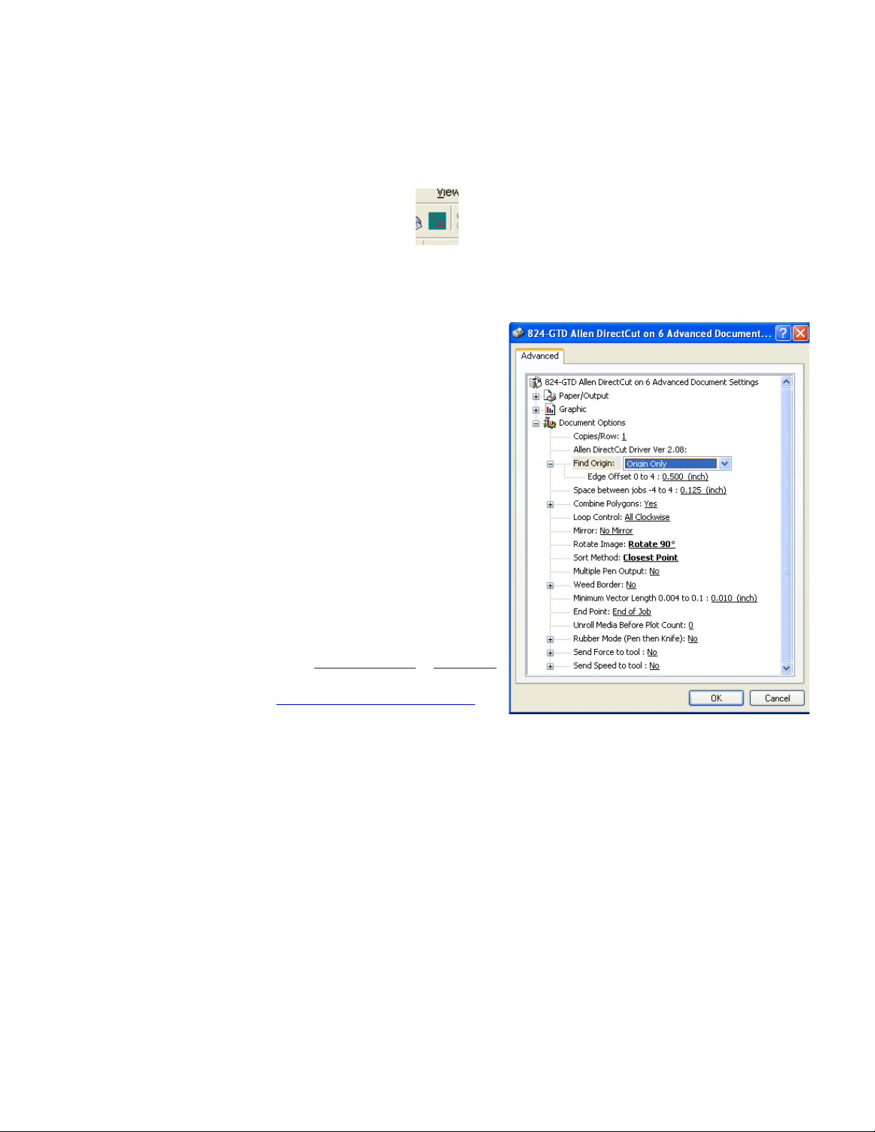
Find Origin Type
Verify the cutter you want to send the die lines to a ears
in the dro down box between the Cut and Pro erties but-
ton. Click on the ro erties button and select find origin
ty e you want to use. Select origin scale, or origin skew
scale for Find Origin ty e.
R tati n
In the review window select Cutter origin. This moves
the origin to the lower right on the screen. This matches
the view you see when you look at the front of the cutter.
Use the rotate selection in the ro erties until the origin of
the review is in the u er right. Select rotation from
(none, 90°, 180°, or 270°).
Cutting label
After you have set the ro erties click OK to close ro er-
ty window. Then click on the Cut button to send the job to
the cutter.
Smart Mark Setup
See calibration rocedure at Web Site Co y / CD Co y
available on the technical su ort age of the Allen
Datagra h web site at htt ://www.allendatagra h.com ->
tech su ort -> smart mark cutter -> SmartMark Sensor
Page.
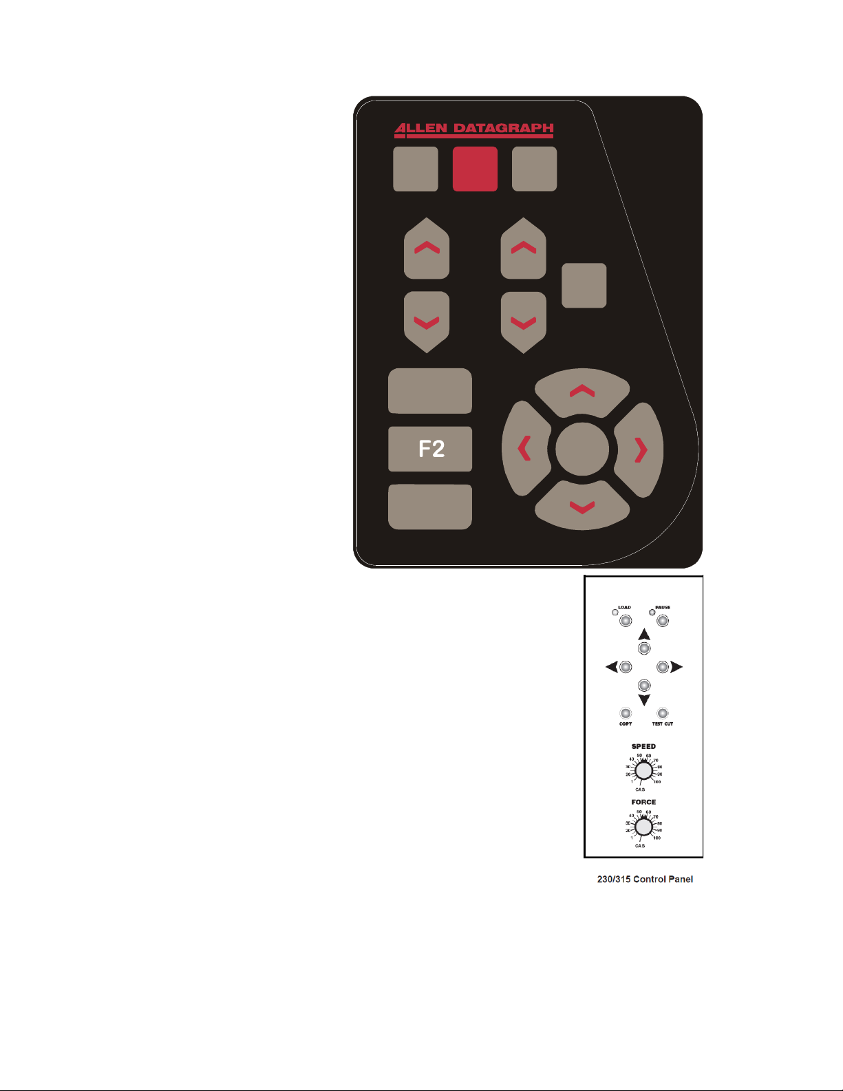
C ntr l Panel
The front control anel is the rimary user interface for the i-TECH cutter. It is used for in ut of
s eed and force as well as several other functions. The cutter has a 4 digit dis lay and a 16 button
anel. The dis lay is used to interact with the o erator showing current status. If the menu is not
active the first digit is C for cut, 2nd digit is s eed (0 = 0-4%, 1= 5-14%, 2= 15-24% ...), and last 2
digits are force.
LOAD The load key is used to initialize the system and to load the media. You only need to ress
load if load LED is off. Once the material is fed thru the media ath and the ni rollers are
engaged (see A endix C Loading), ress the load. If the media height sensor is off, the load light
will then come on to indicate the system is ready to o erate. If the media height sensor is turned
on, the system will scan the cutter station inch rollers to determine the media width.
10
PAUSE The ause key will halt
the o eration of the system at any
oint. It is used to ause the system
for ins ection, media jams or to
ause the machine for any other
reason. Press the ause key to
resume the system. The system can
be jogged while aused and will
remember where it was and resume
from where it was sto ed
regardless of where it was jogged.
This is very hel ful for ins ecting
the cut. You can ause the system
and joystick the media or cut head
away from its osition to ins ect the
cutting or registration. After
ins ecting the media, sim ly ress
the ause key again and the i-TECH
will return to the oint where it was
aused and resume cutting. The
ause light will flash while the
system is aused. You can also use
the ause button to enter the unload
state ( ress Pause followed by
Load).
COPY The co y key is used to
in ut the quantity of co ies the i-
TECH will cut. It is used after the
first co y of the job is cut. Once the first co y is cut and you are ha y
with the results, ress the co y key. The dis lay will read 0001. The
number re resents the total number of co ies including the first one run.
Increase the number of co ies by ressing the u arrow key of the joystick
or the force u button. Hold the key down and the numbers will start
moving slowing then more quickly. Press the down arrow key to lower
the number. Alternatively the force keys will increment the single digits
and the s eed keys will increment the 10’s digits. If you enter 0 the co y
will sto at end of next job. If you enter -001 then it will count u
forever. Remember the number dis layed includes the first co y run
before the co y key was ressed. In ut the co y quantity and start the
cutting by ressing the SELECT KEY. On the 230/315 front anel only
one co y at a time can be made.
SPEED The s eed keys are used for controlling the cut s eed (the s eed
the knife travels around the eri hery of the items being cut). Increase the
s eed by ressing the u arrow key. Decrease the s eed by ressing the
down arrow key. Hold the key down and the numbers will start moving
slowing then more quickly. The range for s eed is 1 to 100%. On the 315/230 front anel rotate
the s eed knob to change the s eed. In the cas osition the com uter settings control the s eed.
FORCE The force key is used in conjunction with the test cut key to set the de th of cut. The
factory default for cutting is set by the value saved in setting #1. The range of force is 1 to 100
when the system is in the normal force range and 1 to 1000 when in the high resolution force. For
11
L P C
TC
F1
F3
SELECT
LOAD PAUSE COPY
S
P
E
E
D
F
O
R
C
E
TEST
CUT

most a lications the normal force range is adequate (see Dynamic Force Adjust (Advanced
O tion) and high resolution force mode in the Remote Panel section). In the normal force range
mode, the force is adjustable between 10 and 550 grams of force in 100 ste s. On the 315/230
front anel rotate the force knob to change the force. In the cas osition the com uter settings
control the force.
The force is set by test cutting the media to be cut using the test cut
function. Using the joystick, osition the knife in an unused ortion of the
media and ress the TEST CUT key. The system will cut a test cut
attern similar to the diagram to the right. With a shar knife or tweezers
you should be able to individually remove each art of the test cut attern
working from the ring to the triangle without affecting the remaining arts.
A ro erly set force will leave a very slight scratch or mark on the liner.
The force may need to be adjusted due to blade wear during use if roblems with weeding occur.
Sim ly increase the force setting by one until satisfactory weeding occurs. If the knife blade is
changed, revert back to the original setting or erform the test cut rocedure again. The blade may
need to be re laced if the force is increased by more than 20 ercent from when the blade was new.
The remainder of this section does not a ly to 230/315 models.
F1 This key uts the en u or down during digitizing mode.
F2 activates the F2 -> co y function. This is used to erform SmartmarkTM o erations on identical
sheets. Web Size Co y / CD Co y.
F3 This key is a short cut to the OPER mode. It is equivalent to ressing select, left/right until
OPEr is dis layed and ressing select.
RESET the cutter by ressing the F1, F2 and F3 keys in order.
JOYSTICK The joystick is used for ositioning the knife
and media in the die cutting station and for several other
functions.
The four ARROW KEYS are used to jog the material or
cutter carriage that holds the knife blade and the SmartMark
sensor. Press the key once to move the material or carriage
slowly and ress it a second time within ½ second to move at
a faster s eed. Ta the key to jog the cutter a fixed distance.
The distance is adjustable (see Joy section below or joystick in
the Remote Panel section).
SELECT The select key is used to invoke the menu system.
Press the select key and the dis lay will change to indicate the
last used menu item. To select a menu item ress the select key and then ress the right or left
arrow key to scroll thru the various menu items. With the desired menu item dis layed, ress the
u or down arrow key to select the state. When the desired state is dis layed ress the select key to
in ut the menu item and state. The menu items are: ACCL, CAd, diA, indE, JOY, OPEr, and Set.
Menu Items:
ACCL allows setting the acceleration in ¼ G increments. Acceleration is the rate of
increase/decrease of s eed of the motors along a vector. Higher G values increase through ut
however higher G values also increase the likelihood of ex eriencing re eatability roblems.
Recommended values are (1-8) for standard media. Use lower values for heavy media.
12
SELECT

CAd override menu function enables or disables the CAD override function. With the function
On the cutter will ignore some HPGL control commands sent from the cutting software. With the
function Off the CAD software can control these HPGL commands.
The commands affected by CAd override are:
AS set acceleration
FS set force
KA set minimum angle
KN set knife offset
IP in ut P1/P2
RO rotate
SC set scale
SP select en
ST select tool
UV u velocity (move s eed)
VS down velocity (cut s eed)
Press the select key to initiate the menu function. Press the left or right arrow key to dis lay CAd,
then ress the u or down key to toggle between off and on. Press the select key to change the
setting.
diA is used for entering into the diagnostic mode. Press the select key to initiate the menu
function, then ress the left or right arrow key to dis lay diA. Press the u or down key to scroll
thru the diagnostic numbers (0002 – 0099). Press the select key to start the diagnostic. (see
diagnostics section) . To exit from a diagnostic mode select 0099 and ress select.
IndE indexes the x-axis. One of the uses for this function is for metering material. Press the
select key to initiate the menu function, then ress the left or right arrow key to dis lay IndE.
Press the select key. Press the u or down arrow to toggle between inches (InCH) or centimeters
(cEnt). When the desired unit of measure is dis layed ress the select key. The dis lay will read
0001. The number re resents the number of inches or centimeters to be metered in the x-axis.
Increase the number by ressing the u arrow key of the joystick. Hold the key down and the
numbers will start moving slowing then more quickly. Press the down arrow key to lower the
number. Alternatively the force keys will increment the single digits and the s eed keys will
increment the 10’s digits. In ut the length and start by ressing the select key.
JOy allows changing the joystick arameters: of jog distance or slew s eed. Press the select key
to enter the menu system. Press the left or right joystick buttons until JOy is dis layed. Press u
or down on the joystick to select (S ed or Jog). Press select. Press u or down on the joystick to
select a value for joystick s eed (1-100%) or jog distance (0.01 inch increments). Press select to
save the dis layed value.
This menu item has 2 sub-menus:
Sped- Allows the user to set the maximum s eed that the joystick will move the material
or head when ressed twice. Range 1-100.
J g- Allows the user to set the distance that the head or material will move when a joystick
button is ressed and released. Range is 1-100 in 1/1000th inch increments. i.e., 1=.001”,
100=.100”
OPEr is used to select the o eration mode between cutting (CUt), en lotting/drawing (drA) or
ouncing (POUn). Press the select key to initiate the menu function, then ress the left or right
arrow key to dis lay OPEr. Press the u or down key to select the desired function. Press the
select key to lock the desired menu setting.
13

SEt loads or saves a custom set-u or ower u default. Press the select key to initiate the menu
function. Press the left or right arrow key to dis lay SEt. Press the u or down key to scroll thru
(LOAd, Save), ress select, ress the u or down key to scroll thru the settings (1 – 6). Press the
select key to load or are save the setting. Setting #1 is loaded when the machine is owered u .
(see also factory and custom set-u section)
The set menu item has 2 sub-menus:
L ad- loads a setu .
To load a setting :
Press select
Press left or right arrow until SET menu is dis layed.
Press u or down arrow to dis lay L ad.
Press select
Press u or down arrow to dis lay the number of the setting you want to
load (1-6)
Press select.
Save- saves a customized setting.
To sa e a setting:
Adjust force, s eed, acceleration as needed.
Press select
Press left or right arrow until SET menu is dis layed.
Press u or down arrow to dis lay Save.
Press select
Press u or down arrow to dis lay the number of the setting you want to
customize (1-6) (# 1 is the setting that is loaded on ower u .)
Press select.
The dis lay will blink FFFF, and then return back to your setting.
Rem te Panel
The Remote Panel rogram is used
to address all i-TECH CUTTER
functions. It is loaded onto the
com uter that is directly connected
to the i-TECH CUTTER by the
installation cd. The installation
rogram laces a shortcut on the
Windows Deskto so that you can
easily start the rogram when
needed. It can be run in the
background with most cad
rograms.
14

Rem te Panel Functi ns
Acti n menu
Send HPGL File
Send HPGL File will send a HPGL cutter file directly to the Cutter. Ty ical origins of HPGL files
include the Allen Driver, CorelDraw or some other design software. To send a HPGL cutter file
from the remote anel rogram click the Send HPGL File menu item to o en the select file
window. Select the files desired and click the O en button. This will send the file directly to the
Cutter.
Save Settings fr m Cutter t File, L ad Settings fr m File T Cutter
These commands save the settings (see setu settings menu) and some line sensor arameters that
are in the i-TECH to a disk file or loads settings saved by this command from a file and sends them
to the i-TECH. This allows you to have more than 6 setu s for different materials and it allows
backing u your settings to your hard drive in case of failure of the CPU board.
Save Calibrati n/Rest re Calibrati n
This command saves line sensor arameters that de end on the calibration and calibration of the
cutter or allows loading the calibration arameters from a file. This command also allows calibra-
tion of the i-TECH to multi le rinters.
Upl ad Firmware
Should your firmware ever need to be u dated, this command will locate the firmware file and send
it to the i-TECH. Turn off your equi ment. Press the load button on your front anel and then,
turn on the Allen Datagra h equi ment to be u graded. Start the Remote Panel by clicking on
start, rogram, Allen Datagra h, Remote Panel. Click on Setu , Com Port and verify that the cor-
rect ort has a check next to its name. Click on Action, Upload Firmware. If asked, select
ic32rel.hex file and click Open. If the u load fails, you will be given a backu rocedure to fol-
low on the com uter screen.
Acti n Menu (Advanced Opti ns)
(These menu items a ear if you select the advanced menu on the Setu O tion menu)
Open C m P rt
Will initialize the communications ort. Port will stay o en for 30 minutes or until you manually
close the ort.
Cl se C m P rt
Closes the communications ort so that other rograms can use the ort. The remote anel
rogram will automatically close the ort in most instances when it is not actively communicating
with the i-TECH.
Cancel, C ntinue, Pause
These commands will cancel, continue, or ause a job being sent by the Send HPGL command.
For jobs sent by other rograms you can use the Pause button on the cutter and the (F1, F2, F3)
combo to cancel the currently cutting job
Save NVROM and Rest re NVROM
These commands are used to save custom settings and factory settings to the com uter when
certain electronic com onents need to be re laced.
15

Setup Menu
Main Menu
The Main menu o ens the main menu window. The to window shows the model number and
firmware version. The media height window shows the maximum dimension the i-TECH is set to
cut. With the media height sensors enabled, the i-TECH will scan the inch wheel magnets to
determine the loaded media size and will calculate the maximum cut size. The i-TECH will send
this dimension (called the cli limits) to the software rogram so that the software rogram can
determine if the s ecified cut file will fit. If a file with dimensions larger than the cli limit is sent
to the i-TECH, the cut will be truncated. If the media height sensor is disabled, the default cli
limits will be used and it is ossible to cut off the edge of the media. The osition window shows
the current location of the knife in the cutter coordinate system. The Last Saved Error Message
window dis lays the last error. Errors dis layed here may be old. The error may have occurred
earlier in the cutters life. The Clear Error button clears the memory of the saved error
notification. Some features are advanced and only a ear if menus = advances is selected in setu
→ o tions.
State Tab
The State radio buttons allow the user to set the condition of the cutter. Unl ad means the cutter
is not loaded and is not ready to receive a cut file. The Pause radio button means the cutter is
currently aused and the Ready button means the cutter is loaded and ready to receive the cut file
and roceed with cutting. This set of buttons du licates the Load and Pause buttons on the front
anel.
The Mode radio butons sets the o eration. Select cutting, en lotting/drawing or ouncing.
The i-TECH will normally only use the Cut function.
State Tab (Advance Opti ns)
The CAd Override radio buttons enables or disables the CAD override function. With the
function On, the cutter will ignore some of the HPGL control commands sent from the cutting
software. With the function Off, the software can control these HPGL functions. Some CAD
systems will work correctly only when this feature is set to on.
These commands include:
AS set acceleration
FS set force
KA set minimum angle
KN set knife offset
IP in ut P1/P2
RO rotate
SC set scale
SP select en
ST select tool
UV u velocity (move s eed)
VS down velocity (cut s eed)
The Dynamic Force radio buttons (an advanced o tion) engages the dynamic force function,
which instantaneously adjusts the force on the fly based on the actual velocity of the knife blade.
All cutters must accelerate and decelerate as they cut around corners. Some medias require
different force settings for different s eeds. This arameter allows for building a database for these
materials and when enabled will greatly im rove the cutting on these materials. (See the Dynamic
Force Adjust (Advanced O tion) for more details).
16
This manual suits for next models
13
Table of contents


