ADTRAN SMART/RG MC60 User manual

/User Manual
Model: MC60 Adapter
Version: 1.1 June 2019
501 SE Columbia Shores Boulevard, Suite 500
Vancouver, Washington 98661 USA
+1 360 859 1780 / smartrg.com

SMARTRG INC. PROPRIETARY AND CONFIDENTIAL. ALL RIGHTS RESERVED. COPYRIGHT © 2016 2
Table of Contents
Table of Contents 2
Welcome! 3
Purpose & Scope 3
Intended Audience 3
Getting Assistance 3
Getting Familiar with your Adapter 4
LED Status Indicators 4
Connections 4
Symbols 5
Logging in to your Adapter's Interface 6
Device Info 7
Node Info 8
Statistics 9
Configuration 10
SW Update 11
APPENDIX A: FCC STATEMENTS 11
FCC Interference Statement 11
FCC Radiation Exposure Statement 12
FCC - PART 68 12
Ringer Equivalency Number Statement 12
IC CS-03 statement 13
Canada Statement 13
5GHz 14
Revision History 15

SMARTRG INC. PROPRIETARY AND CONFIDENTIAL. ALL RIGHTS RESERVED. COPYRIGHT © 2016 3
Welcome!
Thank you for purchasing this SmartRG product.
SmartRG offers solutions that simplify the complex Internet ecosystem. Our solutions include hardware, software, applications,
enhanced network insights, and security delivered via a future-proof operating system. Based in the USA, SmartRG provides local,
proactive software development and customer support. We proudly offer the best, most innovative broadband gateways available.
Learn more at www.SmartRG.com.
Purpose & Scope
This Gateway User Manual provides SmartRG customers with installation, configuration and monitoring information for their MC60
extender.
Intended Audience
The information in this document is intended for Network Architects, NOC Administrators, Field Service Technicians and other net-
working professionals responsible for deploying and managing broadband access networks. Readers of this manual are assumed to
have a basic understanding of computer operating systems, networking concepts and telecommunications.
Getting Assistance
Frequently asked questions are provided at the bottom of the Subscribers page of the SmartRG Web site.
Subscribers: If you require further help with this product, please contact your service provider.
Service providers: if you require further help with this product, please open a support request.
(missing or bad snippet)(missing or bad snippet)
SMARTRG INC. PROPRIETARY AND CONFIDENTIAL. ALL RIGHTS RESERVED. COPYRIGHT © 2016 4
Getting Familiar with your Adapter
This section contains a quick description of the adapter's lights, ports, and buttons to help you get familiar with its operation.
LED Status Indicators
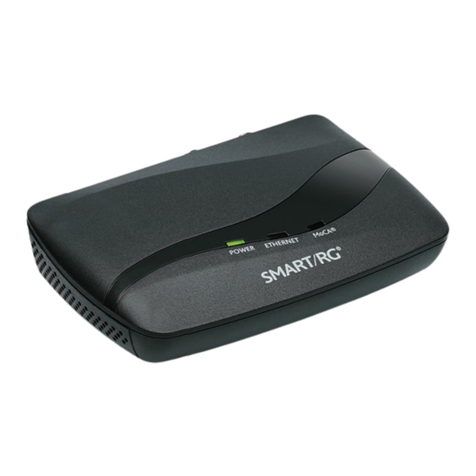
Your SmartRG adapter has three indicator lights (LEDs) on its exterior. The following table describes the LEDs located on top of the
adapter.
INDICATOR COLOR STATE DESCRIPTION
Power White On The device is powered on.
Ethernet Green On A connection is detected.
Green Blink Internet data is being transmitted.
MoCA® Green On This LED glows green briefly (about 1 second) when the adapter has connected with
at least one MoCA.
White Blink Data is being transmitted.
Note: If you disconnect the coax cable from the adapter, this LED reverts to green.
Connections
The connectors and buttons located on the back of the MC60 adapter are shown below and described in the following table.
Feature Description
TV OUT This coax port can be used to connect the adapter to your set-top box or TV.
MoCA® IN This coax port can be used to connect the adapter to the coax wall outlet.
ETHERNET This black RJ45 port can be used to connect a client device such as computers to the adapter.
RESET The Reset button is a small hole in the adapter's enclosure with the actual button mounted behind the sur-
face. This style of push-button prevents the adapter from being inadvertently reset during handling.

SMARTRG INC. PROPRIETARY AND CONFIDENTIAL. ALL RIGHTS RESERVED. COPYRIGHT © 2016 5
Feature Description
If you want to restore the default settings, insert a fine wire (such as a paper clip) into the hole, press the
Reset button gently for 10 seconds, and then release the button. The system reboots and returns to the
factory defaults.
Note: If you press the Reset button for less than 10 seconds, the adapter reboots but no settings are
changed.
Warning: Do not press the Reset button unless you want to clear the current settings.
DC 5V Use only the power supply included with your adapter. Intended for indoor use only.
ON/OFF Power switch.
Symbols
The symbols displayed on the MC60 labeling are explained below.
Symbol Indicates
Polarity of DC power connector.
DC voltage.
AC voltage.
For indoor use only.
Class II equipment.
Energy Efficiency Marking.

SMARTRG INC. PROPRIETARY AND CONFIDENTIAL. ALL RIGHTS RESERVED. COPYRIGHT © 2016 6
Logging in to your Adapter's Interface
To manually configure the MC60 adapter, access its embedded UI.
Note: Before you can access the UI, make sure that your computer's IP (NIC) is set to any other IP address than the default IP address
of the adapter (192.168.0.2).
1. Open a Web browser on your computer.
2. Enter http://192.168.0.2 (the default IP address of the adapter) in the address bar. The Device Info page appears.

SMARTRG INC. PROPRIETARY AND CONFIDENTIAL. ALL RIGHTS RESERVED. COPYRIGHT © 2016 7
Device Info
On this page, you can view information about your device including
lBoard ID: The installed chip.
lSW Version: The embedded software version.
lHW Version: The hardware version.
lMY Version: The firmware version.
lRF Channel: The channel currently in use.
lBand: The active band.
lLink Uptime: How long since the MC60 was linked up.
lCore Uptime: How long since core was activated.
In the left navigation bar, click Device Info. The following page appears.

SMARTRG INC. PROPRIETARY AND CONFIDENTIAL. ALL RIGHTS RESERVED. COPYRIGHT © 2016 8
Node Info
On this page, you can view information about your node including the node name, MAC address,power levels, etc.
In the left navigation bar, click Node Info. The following page appears.

SMARTRG INC. PROPRIETARY AND CONFIDENTIAL. ALL RIGHTS RESERVED. COPYRIGHT © 2016 9
Statistics
On this page, you can view Ethernet statistics.
In the left navigation bar, click Statistics.The following page appears.

SMARTRG INC. PROPRIETARY AND CONFIDENTIAL. ALL RIGHTS RESERVED. COPYRIGHT © 2016 10
Configuration
On this page, you can configure the RF settings.
1. In the left navigation bar, click Configuration. The following page appears.
2. Modify the fields, using the information provided in the table below.
3. Click Submit.
Field Description
RF Channel This option is set to 1400 by default and cannot be changed.
RF Band Select an appropriate RF band. Options are Band D Low,Band D High,Band D Extended,Band E,
Band F,Band C4, and Band H. The default is Band D High.
RF Switch Select the switch level. Options are Hi and Low. The default is Hi.

SMARTRG INC. PROPRIETARY AND CONFIDENTIAL. ALL RIGHTS RESERVED. COPYRIGHT © 2016 11
SW Update
On this page, you can upload a new software image file (firmware) to update your adapter.
1. In the left navigation bar, click SW Update. The following page appears.
2. Click Browse and select the file you want to upload.
3. Click Upload. The new firmware is active the next time you turn the adapter on.
APPENDIX A: FCC STATEMENTS
FCC Interference Statement
This device complies with Part 15 of the Federal Communications Commission (FCC) Rules. Operation is subject to the following two
conditions:
lThis device may not cause harmful interference.
lThis device must accept any interference received, including interference that may cause undesired operation.
This equipment has been tested and found to comply with the limits for a Class B digital device, pursuant to part 15 of the FCC
Rules. These limits are designed to provide reasonable protection against harmful interference in a residential installation. This
equipment generates, uses and can radiate radio frequency energy and, if not installed and used in accordance with the instruc-
tions, may cause harmful interference to radio communications. However, there is no guarantee that interference will not occur in a
particular installation.
If this equipment does cause harmful interference to radio or television reception, which can be determined by turning the equip-
ment off and on, the user is encouraged to try to correct the interference by one or more of the following measures:
lReorient or relocate the receiving antenna.
lIncrease the separation between the equipment and receiver.

SMARTRG INC. PROPRIETARY AND CONFIDENTIAL. ALL RIGHTS RESERVED. COPYRIGHT © 2016 12
lConnect the equipment into an outlet on a circuit different from that to which the receiver is connected.
lConsult the dealer or an experienced radio/TV technician for help.
This Class B digital apparatus complies with Canadian ICES-003.
Cet appareil numrique de la classe B est conforme à la norme NMB-003 du Canada.
FCC Radiation Exposure Statement
This device complies with FCC radiation exposure limits set forth for an uncontrolled environment and it also complies with Part 15
of the FCC RF Rules.
lThis equipment complies with FCC radiation exposure limits set forth for an uncontrolled environment.
lThis equipment should be installed an operated with a minimum distance of 20cm between the radiator and your body.
lThis transmitter must not be co-located or operating in conjunction with any other antenna or transmitter.
This device complies with Part 15 of the FCC Rules. Operation is subject to the following two conditions: (1) this device may not cause
harmful interference, and (2) this device must accept any interference received, including interference that may cause undesired
operation.
Caution! Any changes or modifications not expressly approved by the party responsible for compliance could void the user's author-
ity to operate the equipment.
FCC - PART 68
This equipment complies with Part 68 of the FCC rules and the requirements adopted by the ACTA. On the bottom case of this equip-
ment is a label that contains, among other information, a product identifier in the format US: VW7DL01BSR555A.
This equipment uses the following USOC jacks: RJ-11/RJ45/USB/Power Jacks.
A plug and jack used to connect this equipment to the premises wiring and telephone network must comply with the applicable FCC
Part 68 rules and requirements adopted by the ACTA. A compliant telephone cord and modular plug is provided with this product. It
is designed to be connected to a compatible modular jack that is also compliant. See installation instructions for details.
Ringer Equivalency Number Statement
Notice: The Ringer Equivalency Number (REN) assigned to each terminal device provides an indication of the maximum number of
terminals allowed to be connected to a telephone interface. The termination on an interface may consist of any combination of
devices subject only to the requirement that the sum of the Ringer Equivalence Numbers of all the devices does not exceed 5.
If this equipment causes harm to the telephone network, the telephone company will notify you in advance that temporary dis-
continuance of service may be required. But if advance notice isn't practical, the telephone company will notify the customer as
soon as possible. Also, you will be advised of your right to file a complaint with the FCC if you believe it is necessary.

SMARTRG INC. PROPRIETARY AND CONFIDENTIAL. ALL RIGHTS RESERVED. COPYRIGHT © 2016 13
The telephone company may make changes in its facilities, equipment, operations or procedures that could affect the operation of
the equipment. If this happens the telephone company will provide advance notice in order for you to make necessary modifications
to maintain uninterrupted service.
If trouble is experienced with this equipment, for repair or warranty information, please contact SmartRG,Inc. If the equipment is
causing harm to the telephone network, the telephone company may request that you disconnect the equipment until the problem
is resolved.
Connection to party line service is subject to state tariffs. Contact the state public utility commission, public service commission or
corporation commission for information.
If your home has specially wired alarm equipment connected to the telephone line, ensure the installation of this device does not
disable your alarm equipment. If you have questions about what will disable alarm equipment, consult your telephone company or a
qualified installer.
IC CS-03 statement
This product meets the applicable Industry Canada technical specifications. / Le présent matériel est conforme aux specifications
techniques applicables d’Industrie Canada
The Ringer Equivalence Number (REN) is an indication of the maximum number of devices allowed to be connected to a telephone
interface. The termination of an interface may consist of any combination of devices subject only to the requirement that the sum of
the RENs of all the devices not exceed five. / L’indice d’équivalence de la sonnerie (IES) sert à indiquer le nombre maximal de ter-
minaux qui peuvent être raccordés à une interface téléphonique. La terminaison d’une interface peut consister en une combinaison
quelconque de dispositifs, à la seule condition que la somme d’indices d’équivalence de la sonnerie de tous les dispositifs n’excède
pas cinq.
Canada Statement
This device complies with Industry Canada licence-exempt RSS standard(s). Operation is subject to the following two conditions: (1)
this device may not cause interference, and (2) this device must accept any interference, including interference that may cause
undesired operation of the device.
Le présent appareil est conforme aux CNR d'Industrie Canada applicables aux appareils radio exempts de licence. L'exploitation est
autorisée aux deux conditions suivantes : (1) l'appareil ne doit pas produire de brouillage, et (2) l'utilisateur de l'appareil doit
accepter tout brouillage radioélectrique subi, même si le brouillage est susceptible d'en compromettre le fonctionnement.
The device meets the exemption from the routine evaluation limits in section 2.5 of RSS 102 and compliance with RSS-102 RF expos-
ure, users can obtain Canadian information on RF exposure and compliance.
Le dispositif rencontre l'exemption des limites courantes d'évaluation dans la section 2.5 de RSS 102 et la conformité à l'exposition de
RSS-102 rf, utilisateurs peut obtenir l'information canadienne sur l'exposition et la conformité de rf.
This transmitter must not be co-located or operating in conjunction with any other antenna or transmitter. This equipment should
be installed and operated with a minimum distance of 20 centimeters between the radiator and your body.

SMARTRG INC. PROPRIETARY AND CONFIDENTIAL. ALL RIGHTS RESERVED. COPYRIGHT © 2016 14
Cet émetteur ne doit pas être Co-placé ou ne fonctionnant en même temps qu'aucune autre antenne ou émetteur. Cet équipement
devrait être installé et actionné avec une distance minimum de 20 centimètres entre le radiateur et votre corps.
This radio transmitter (identify the device by certification number, or model number if Category II) has been approved by Industry
Canada to operate with the antenna types listed below with the maximum permissible gain and required antenna impedance for
each antenna type indicated. Antenna types not included in this list, having a gain greater than the maximum gain indicated for that
type, are strictly prohibited for use with this device.
Le présent émetteur radio (identifier le dispositif par son numéro de certification ou son numéro de modèle s'il fait partie du
matériel de catégorie I) a été approuvé par Industrie Canada pour fonctionner avec les types d'antenne énumérés ci-dessous et
ayant un gain admissible maximal et l'impédance requise pour chaque type d'antenne. Les types d'antenne non inclus dans cette
liste, ou dont le gain est supérieur au gain maximal indiqué, sont strictement interdits pour l'exploitation de l'émetteur.
5GHz
5150-5250 MHz band is restricted to indoor operations only.

SMARTRG INC. PROPRIETARY AND CONFIDENTIAL. ALL RIGHTS RESERVED. COPYRIGHT © 2016 15
Revision History
Revision Date Description
1.1 June 2019 Updated content to reflect changes in physical design of the
product.
1.0 Sept 2016 Initial release of this user manual.
Other manuals for SMART/RG MC60
1
Table of contents
Other ADTRAN Adapter manuals

ADTRAN
ADTRAN NetVanta 7000 Series How to use

ADTRAN
ADTRAN Express 6530 User manual

ADTRAN
ADTRAN Quad BNC Instruction Manual

ADTRAN
ADTRAN 1442880F1 User manual

ADTRAN
ADTRAN 1442820G1 User manual

ADTRAN
ADTRAN ISU 128 Guide

ADTRAN
ADTRAN Total Access 750 U-BR1TE Instruction Manual

ADTRAN
ADTRAN Express NTU ISDN Terminal Adapter User manual

ADTRAN
ADTRAN SMART/RG MC60 User manual