manuals.online logo
Brands
  1. Home
  2. •
  3. Brands
  4. •
  5. ADTRAN
  6. •
  7. Network Hardware
  8. •
  9. ADTRAN jobAid Total Access 838 User manual

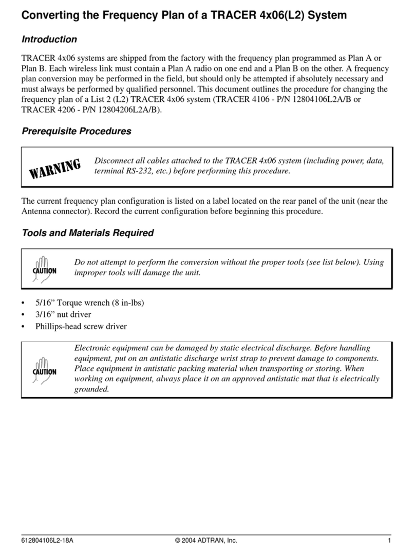
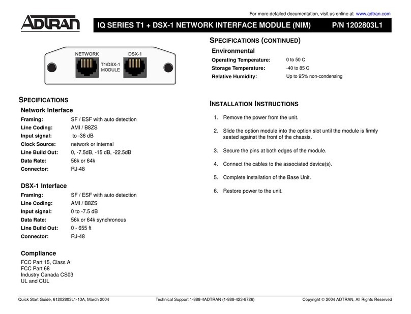
ADTRAN jobAid Total Access 838 User manual

jobAid
1
DESCRIPTION
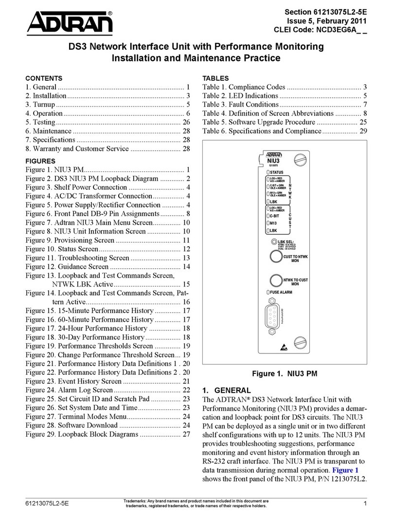
TheTotalAccess838SHDSLEthernetintheFirstMile(EFM)isa
Metro‐EthernetForum(MEF)compliant,EFMbondedLTU
designedforcost‐effectivedeploymentofvoiceanddataservices
tosmallandmediumsizebusinessessupportinguptoeighttwo‐
wireSHDSLloops.Eachcopperpairprovidessealingcurrentin
accordancewithITU‐TG.991.2whentrainedwithanADTRAN
NTU.TheTotalAccess838acceptsSHDSLoreSHDSLand
delivers10/100Base‐TEthernetandGigabitEthernetforcustomer
LANextension.TheTotalAccess838terminatestheSHDSLloops
inanRJ‐21connectorandsupportsdataratesfrom192kbpsto5.7
Mbpspercopperpair.TheTotalAccess838providesanaggregate
datarateupto45.6MbpsoverasingleEFMbondinggroup.
Features
♦MEFCompliant
♦OneintegratedEIA‐232configurationport
(DCE)
♦Fourintegrated10/100Base‐TEthernetports
♦OneGigabitEthernetport
♦Eighttwo‐wireeSHDSLloops
♦WANProtocol:IEEE802.3ahEFMbonding
♦CommandLineInterface(CLI)
♦FrontpanelLEDs
♦Wallmountinghardwareincluded
♦RemoteManagement‐CLIusingVirtualTerminal,Telnetby
wayofManagementVLAN
♦SealingcurrentinaccordancewithITU‐TG.991.2
NOTE
Duetocompliancecertificationrequirements,useonlySFPs
approvedbyADTRAN.ADTRANcannotcertifysystemintegrity
withotherSFPs.Toensurecompatibility,refertothe
documentationprovidedwitheachSFP.
Total Access 838
SHDSL EFM LTU
INSTALLATION AND TURN-UP
Afterunpackingtheunit,inspectitfordamage.Ifdamageis
noted,fileaclaimwiththecarrierandthencontactADTRAN.For
moreinformation,refertothewarranty.
ThemountingoptionsfortheTotalAccess838arerackmountor
wallmount.FollowthestepslistedbelowtoinstalltheTotalAccess838.
1. AttachmountingbracketstothesideoftheTotalAccess838
inthecorrectorientationforeitherrackmountorwallmount
usingthetwoscrewsprovidedforeachbracket(refertothe
illustrationbelowforthecorrectorientation).
WARNING
!
Donotupsetthestabilityoftheequipmentrackafterinstallation
iscomplete.
2. SecuretheTotalAccess838totherackorwall.
♦ForRackmount:SecuretheTotalAccess838tothe
equipmentrackwiththeappropriatescrews.
♦ForWallmount:Preparethemountingsurfaceby
attachingaboard(typicallyplywood,3/4”to1”thick)to
thewallstudsusingappropriatelagbolts.Securethe
TotalAccess838totheplywoodusingtwo3/32”to1/8”
woodscrewsatleast1”inlength.
3. Connecttheframegroundfromthechassisgroundlugonthe
upperrightrearpaneloftheTotalAccess838totheequipment
rackgroundingscreworotherappropriategroundingconnection.
19 inch
23 inch
Wall Mount
Mounting Bracket Orientations
CLEI: SIM5J10B_ _
Product P/N: 1200633G7
Issue Date: August 2010
Document P/N: 61200633G7-22B
5
6
7
8
1
2
3
4
LOOP STATUS
GE
CRAFT
SHDSL
ACO
1 2 3 4
ETH
ACT
ALARM
EFM
GIG E
1200633
48V ....., 2A
24V ....., 3A
NC CNO NC CNO NC CNO
ALARM CONTACTS
CRIT MAJOR MINOR
IN
USE COPPER
CONDUCTORS ONLY
+
PWR RET
A
PWR RET
B
AC
ALM
261200633G7-22B
CONNECT AND LOGIN TO SYSTEM
ConnecttothefrontpanelRS‐232,DB‐9connectorlabeledCRAFT
tologonandprovisiontheTotalAccess838bywayofVT100
terminalorVT100terminalemulationsoftwaresuchasHyperTer‐
minalorProCommPlus.
Craftportdefaultsareasfollows:
♦DataRate:Auto(Availabledataraterange9600‐115200)
♦AsynchronousDataFormat:8‐databits,noparity,1‐stopbit,
andnoflowcontrol
PressENTERtoactivatetheCLI.
NOTE
Thedefaultusernameandpasswordare“A D M I N ” and
“PASSWORD”inallcapitalletters.
FRONT PANEL PUSHBUTTON
FRONT PANEL LEDS
Label Function
ACO ThefrontpanelACO(AlarmCutOff)switchdisablesthe
alarmindications.
Label Status Indication
ACT {
z
z/z
z
z/z
z
Off
Green
Green/Yellow
Alternating
Yellow
Yellow/Red
Alternating
Red
Poweroff
Normaloperation
Normaloperationandconsole
open
Softwareupdateinprogress
Self‐testfailedandconsole
open
Self‐testfailed(notbootable)or
devicemalfunctioned
ALARM z
z
2
Green
Red
RedFlashing
Nocritical,major,orminor
alarmsonwhenInService
Activemajororminoralarm
Activecriticalalarm
EFM z
z
z
2
Green
Yellow
Red
RedFlashing
AllInServiceEFMgroupsare
operatingnormally
AtleastoneEFMgroupisin
test
AtleastoneInServiceEFM
groupisinafailedstate
AtleastoneInServiceEFMlink
isinafailedstate
ETH 1–4 {
z
2
Off
Green
YellowFlashing
NoEthernetlinkpresent
10/100Base‐TEthernetlinkis
up
Activereceiveortransmit
Ethernetactivity
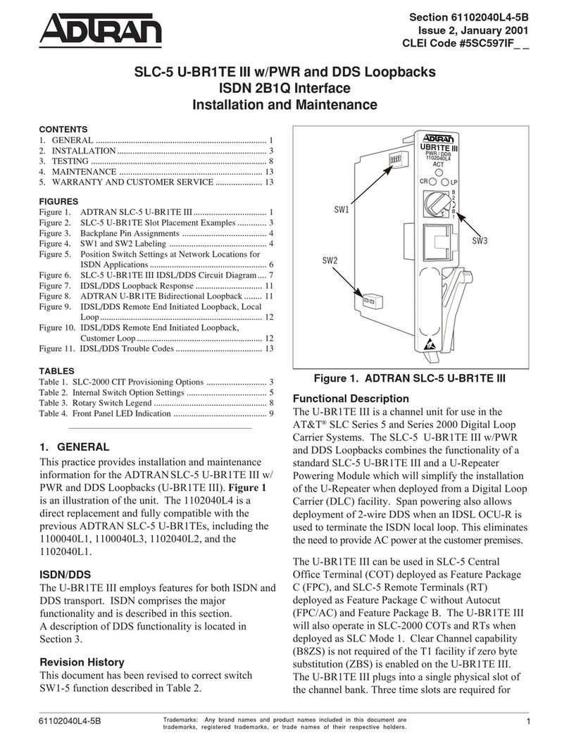
4. MakepowerconnectionstotheTotalAccess838.
a. Determinewhichfusepairsaretosupplypowertothe
TotalAccess838.
b. RemovethefusesfromtheA
andBslotsforthepair.
c. Connect RET A,PWR A,RET B,and
PWR B tothepowerconnector.
PWR referstorespective–48VDC
or±24VDCpowersources;RET
referstorespectivereturns.
NOTE
♦ Areadilyaccessibledisconnectdevice,suchasarackmount
fuseandalarmpanelthatissuitablyapprovedandrated,
shouldbeincorporatedintothefixedwiring.
♦ Connecttoareliablygrounded–48VDCor±24VDCsource
thatiselectricallyisolatedfromtheACsource.
♦ Thebranchcircuitovercurrentprotectionshouldbeaslow‐
blowfuseorcircuitbreaker.
WARNING
!
Installingfusesinthefuseandalarmpanelatthisstagewill
providepowertotheTotalAccess838.Therewillbepowerto
pinsandconnectorsontherearpanelandinsidetheTotalAccess
838.Exercisecautiontoavoidelectricalshock.
5. Applypowerandcheckvoltages.
a. Installappropriatefusesintheslotsofthefuseand
alarmpanelthatservestheTotalAccess838.
b. Usingavoltmeter,verifythattheoperatingvoltageis
withinthespecificationsforAorBpowerfeeds.For
moreinformation,refertoSpecifications.
6. Removetheprotectivecoverfromthealarmwirewrap
terminals.
7. ConnecttheAC ALM (ACalarm),CRIT(critical),MAJOR,andMINOR
alarmleadsfromthealarmpaneltotheCommon(C),
NormallyOpen(NO),andNormallyClosed(NC)wire‐wrap
terminalsontheTotalAccess838rearpanelasrequired.
NOTE
TheACalarminputfunctionsasfollows.Allvoltagesdescribed
belowaremeasuredwithrespecttothereturn(RET)inputtothe
TotalAccess838.
♦ Whenpowerisnegative(e.g.–48V),thealarmistriggered
whenthevoltageontheACalarmpinisatleast5Vabovethe
potentialonthePWRinput.Forexample,ifthevoltageonthe
PWRinputis–54V,thenthealarmwilltriggerifthevoltageon
theACalarmpinisbetween–49Vand0VwithrespecttoRET.
♦ Whenpowerispositive(e.g.24V),thealarmistriggeredwhen
thevoltageontheACalarmpinisatleast5VabovetheRET
input.Forexample,ifthevoltageonthePWRinputis+24V,
thenthealarmwilltriggerifthevoltageontheACalarmpinis
between5Vand24VwithrespecttoRET.
PWR B RET
PWR A RET
PWR A
PWR B
61200633G7-22B 3
CRAFT PORT PINOUT
Thetablebelowliststhepinoutforthecraftport.
10/100BASE-T ETHERNET PORT PINOUT
Thetablebelowliststhepinoutforthe10/100Base‐TEthernetport.
GIG E {
z
z
z
Off
Green
Yellow
Red
NoSFPpresent
ApprovedSFPpresentandlink
isup
Non‐approvedSFPpresentand
linkisup
SFPpresentandlinkisdown
LOOP
STATUS
1–8
{
z
2
2
z
z
2
Off
Green
GreenFlashing(slow)
GreenFlashing(fast)
Yellow
Red
RedFlashing
SHDSLloopisdisabled
SHDSLloopistrainedupand
EFMgroupisestablished
SHDSLloopiscurrently
training
SHDSLloopisacquiringEFM
synchronization
SHDSLloopisinhibiteddueto:
1. Localloopbackinitiated
2. Detectionofremote
loopback
3. Loophasbeenremoved
fromefm‐linkdueto
excessivecodeviolations
SHDSLloopisnottrainedup
SHDSLloopisinthehand‐
shakeprocess
Pin Name Description
1–NoConnection(NC)
2 RD ReceiveData(Output)
3 TD TransmitData(Input)
4DTRDataTerminalReady
5SGSignalGround
6–NC
7–NC
8–NC
9–NC
Pin Name Description
1 TX1 TransmitPositive
2 TX2 TransmitNegative
3 RX1 ReceivePositive
4–NC
5–NC
6 RX2 ReceiveNegative
7–NC
8–NC
Label Status Indication RJ-21 SHDSL PORT PINOUT
ThetablebelowliststhepinoutfortheRJ‐21SHDSLport.
DEPLOYMENT GUIDELINES
ThetablebelowliststhemaximumrateoftheSHDSLportforthe
associatedlinedistance.
RESOURCES
Thefollowingtableoutlinesthemaximumavailableresourcesfor
configuringthelogicalinterfaces.Errormessagesoccuronce
resourcesareexhausted.
Pin Port Description Pin Port Description
11 Ring 261 Tip
22 Ring 272 Tip
33 Ring 283 Tip
44 Ring 294 Tip
5 5 Ring 30 5 Tip
6 6 Ring 31 6 Tip
7 7 Ring 32 7 Tip
8 8 Ring 33 8 Tip
Rate (kbps) Length (ft)*
5696 2800
4096 3600
3088 5100
2304 6300
1544 7900
1024 9800
768 11000
384 14800
192 19800
*26AWGwiresizeminimum
Resource Maximum
EVCs 64
EVCMaps 64
Policers 64
EFMGroups 4
Warranty: ADTRAN will replace or repair this product within the warranty period if it does not
meet its published specifications or fails while in service. Warranty information can be
found online at www.adtran.com/warranty.
©2010 ADTRAN, Inc. All Rights Reserved.
ADTRAN CUSTOMER CARE:
From within the U.S. 1.800.726.8663
From outside the U.S. +1 256.963.8716
PRICING AND AVAILABILITY 1.800.827.0807
*61200633G7-22B*
SPECIFICATIONS
SpecificationsfortheTotalAccess838SHDSLEFMareasfollows:
♦Electrical
◊InputVoltagerating(s):
•–48VDC(Operatingrangeof–42.5VDCto–56.5VDC)
•±24VDC(Operatingrangeof±20VDCto±28.25VDC)
•AorBPowerFeed
◊InputCurrentRating(s):
•2.0amps(–48VDC)
•3.0amps(±24VDC)
◊MaximumCurrentDraw:
•370mA(–48VDC)
•740mA(±24VDC)
◊MaximumPower:18watts
♦Environmental
◊OperationalTemperatureRange:–40°Cto+65°C
◊OperatingAltitudeRange:–197feet(–60meters)to13000
feet(4000meters)
•From–197feet(–60meters)to6000feet(1800meters)the
operatingtemperatureisderatedby1.6°C/1000feet.
•From6000feet(1800meters)to13000feet(4000meters)
theoperatingtemperatureisderatedby1.4°C/1000feet.
◊StorageTemperatureRange:–40°Cto+85°C
◊RelativeHumidity:upto95%,noncondensing
♦Physical
◊Height:1.72inches
◊Width:19.0inches
◊Depth:11.97inches
◊Weight:6lbs
♦Connectors
◊SHDSLPort:RJ‐21,135ohms
◊10/100Base‐TEthernet:RJ‐45
◊GigabitEthernet:SmallForm‐factorPluggable(SFP)
◊CraftPort:DB‐9female
♦DiagnosticsandTest
◊Self‐diagnosis
SAFETY AND REGULATORY COMPLIANCE
RefertotheTotal Access838SHDSLEFMLTUSafetyandRegulatory
ComplianceNotice(P/N61200633G7‐17)fordetailedsafetyand
regulatoryinformation.
C A U T I O NC A U T I O N !
SUBJECT TO ELECTROSTATIC DAMAGE
OR DECREASE IN RELIABILITY.
HANDLING PRECAUTIONS REQUIRED.

Other ADTRAN Network Hardware manuals

ADTRAN MX2800 STS-1 User guide

ADTRAN

ADTRAN MX2800 STS-1 User guide

ADTRAN 1442390G1 User manual

ADTRAN

ADTRAN 1442390G1 User manual

ADTRAN NetVanta 6330 Series User manual

ADTRAN

ADTRAN NetVanta 6330 Series User manual

ADTRAN NetVantaE1/FE1 User manual

ADTRAN

ADTRAN NetVantaE1/FE1 User manual

ADTRAN HDSL 3192 HTU-C Instruction Manual

ADTRAN

ADTRAN HDSL 3192 HTU-C Instruction Manual

ADTRAN Total Reach DDS-DP 5 Series Instruction Manual

ADTRAN

ADTRAN Total Reach DDS-DP 5 Series Instruction Manual

ADTRAN DDS T200 Instruction Manual

ADTRAN

ADTRAN DDS T200 Instruction Manual

ADTRAN T200 H2TU-R Instruction Manual

ADTRAN

ADTRAN T200 H2TU-R Instruction Manual

ADTRAN 500 Series User manual

ADTRAN

ADTRAN 500 Series User manual

ADTRAN DSU IV ESP User manual

ADTRAN

ADTRAN DSU IV ESP User manual

ADTRAN 1442940G1 User manual

ADTRAN

ADTRAN 1442940G1 User manual

ADTRAN Total Access DSLAM Octal SHDSL User manual

ADTRAN

ADTRAN Total Access DSLAM Octal SHDSL User manual

ADTRAN HTU Nx64 User manual

ADTRAN

ADTRAN HTU Nx64 User manual

ADTRAN Express 3000 User manual

ADTRAN

ADTRAN Express 3000 User manual

ADTRAN NetVanta 5660 User manual

ADTRAN

ADTRAN NetVanta 5660 User manual

ADTRAN T200 H4R User manual

ADTRAN

ADTRAN T200 H4R User manual

ADTRAN U-BR1TE User manual

ADTRAN

ADTRAN U-BR1TE User manual

ADTRAN ATLAS 800 Series Module QUAD E1 User guide

ADTRAN

ADTRAN ATLAS 800 Series Module QUAD E1 User guide

ADTRAN NetVanta 1224 Instruction Manual

ADTRAN

ADTRAN NetVanta 1224 Instruction Manual

ADTRAN NetVanta 6355 PoE User manual

ADTRAN

ADTRAN NetVanta 6355 PoE User manual

ADTRAN 414 RG User manual

ADTRAN

ADTRAN 414 RG User manual

ADTRAN NetVanta 1000 Series Manual

ADTRAN

ADTRAN NetVanta 1000 Series Manual

ADTRAN NetVanta 1335 Series User manual

ADTRAN

ADTRAN NetVanta 1335 Series User manual

ADTRAN Total Access 374 Product manual

ADTRAN

ADTRAN Total Access 374 Product manual

Popular Network Hardware manuals by other brands

DCB 8 DBRA Setup and configuration guide

DCB

DCB 8 DBRA Setup and configuration guide

Spirent B2-800-QD-4-T1S installation instructions

Spirent

Spirent B2-800-QD-4-T1S installation instructions

EnGenius IEEE 802.11b Outdoor Wireless Client Bridge user manual

EnGenius

EnGenius IEEE 802.11b Outdoor Wireless Client Bridge user manual

DPS Telecom ECU LAN user manual

DPS Telecom

DPS Telecom ECU LAN user manual

ZyXEL Communications USG FLEX 500 quick start guide

ZyXEL Communications

ZyXEL Communications USG FLEX 500 quick start guide

Compatible Systems 8 Port 10 RIOP installation guide

Compatible Systems

Compatible Systems 8 Port 10 RIOP installation guide

Paradyne Jetstream CPX-1000 installation guide

Paradyne

Paradyne Jetstream CPX-1000 installation guide

Scala Player-S Setup guide

Scala

Scala Player-S Setup guide

Mirapoint RazorSafe 170 Getting started guide

Mirapoint

Mirapoint RazorSafe 170 Getting started guide

Datacom Systems WANswitch W2358DSL Hardware guide

Datacom Systems

Datacom Systems WANswitch W2358DSL Hardware guide

SiFive FE310-G003 manual

SiFive

SiFive FE310-G003 manual

Johnson Controls Facility Explorer Technical bulletin

Johnson Controls

Johnson Controls Facility Explorer Technical bulletin

Cymbol G3 Series user guide

Cymbol

Cymbol G3 Series user guide

Draper IntelliFlex I/O C156.267 user manual

Draper

Draper IntelliFlex I/O C156.267 user manual

ZLG CANFDBridge Smart user manual

ZLG

ZLG CANFDBridge Smart user manual

FieldServer Weigh-Tronix FS-8700-36 Driver manual

FieldServer

FieldServer Weigh-Tronix FS-8700-36 Driver manual

Cisco ISA550 Administration guide

Cisco

Cisco ISA550 Administration guide

VERITAS Access 3340 Appliance Product Description

VERITAS

VERITAS Access 3340 Appliance Product Description

manuals.online logo
manuals.online logoBrands
  • About & Mission
  • Contact us
  • Privacy Policy
  • Terms and Conditions

Copyright 2025 Manuals.Online. All Rights Reserved.