manuals.online logo
Brands
  1. Home
  2. •
  3. Brands
  4. •
  5. ADTRAN
  6. •
  7. Network Hardware
  8. •
  9. ADTRAN HDSL4 User manual

ADTRAN HDSL4 User manual

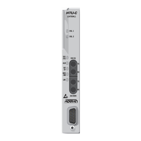
HDSL4 T200 H4TU-R FOR LOCAL POWER JOBAID
61221424L1-22A
0208
TX
RX
REM
LOC
LBK
1221424L1
DSL 1
DSL 2
DS1
ALM
(GRN)
(YEL)
ESF/SF
(GRN)
(YEL)
(GRN)
(YEL)
B8ZS/AMI
LBK/RLB
RX
M
O
N
TX
R
S
2
3
2
HDSL4 T200
H4TU-R
CLEI: T1L5J61C_ _
LED STATUS
DSL1/DSL2 ●Green Normal operation; signal quality (SNR Margin) is optimum on
Loop 1/Loop 2 between the H4TU-C and the H4TU-R.
●Red Severely impaired operation; signal quality (SNR Margin) is 0 dB on
Loop1/Loop 2 between the H4TU-C and the H4TU-R.
DS1 ●Green DS1 signal from the CPE is present at the H4TU-R.
●Red DS1 signal from the CPE is absent at the H4TU-R.
ALM ●●Off No alarm condition detected.
●Red Alarm condition detected either locally (H4TU-R) or locally and
remotely (H4TU-R and H4TU-C).
●Yellow Remote (H4TU-C) alarm condition detected.
ESF/SF ●●Off Indicates received DS1 signal is unframed.
●Green Indicates received DS1 signal is SF framed.
●Yellow Indicates received DS1 signal is ESF framed.
B8ZS/AMI ●Green The unit is receiving AMI line code.
●Yellow The unit is receiving B8ZS line code.
LBK/RLB ●●Off Unit is not in the armed or loopback state.
●Yellow A local loopback is active on this specific unit.
●Green A remote loopback is active on this specific unit.
NOTE: When used with an ADTRAN H4TU-C, the terminal screens via the H4TU-R will display
information that is stored at the H4TU-C.
OPTIONS
Faceplate Buttons
LOC Initiates a bidirectional loopback of the H4TU-R toward the network and customer
REM Initiates a loopback at the H4TU-C toward the customer
POWER
This specific unit is intended for Local Power Only. If a Span Powered unit is needed, refer to
P/N 1221426L1.
DS1 MONITOR JACKS
TX DS1 signal from CPE toward Network
(nonintrusive)
RX DS1 signal from Network toward CPE
(nonintrusive)
COMPLIANCE
Warning: The DSX-1 interface is intended for
connection to intra-building wiring only.
Ensure chassis ground is properly connected.
This product is intended for installation in
restricted access locations only and in equipment
with a Type “B” or “E” enclosure.
This product meets all requirements of Bellcore
GR-1089-CORE (Class A2), ANSI T1.418-2002.
This product is NRTL listed to the applicable UL
standards.
Code Input Output
Power Code (PC) C C
Telecommunication Code (TC) X X
Installation Code (IC) A –
C A U T I O N
C A U T I O N
!
SUBJECT TO ELECTROSTATIC DAMAGE
OR DECREASE IN RELIABILITY.
HANDLING PRECAUTIONS REQUIRED.
1
2
3
4
5
6
7
8
9
10
11
12
13
14
15
16
17
18
19
20
21
22
23
24
25
26
27
28
29
30
31
32
33
34
35
36
37
38
39
40
41
42
43
44
45
46
47
48
49
50
51
52
53
54
55
Chassis Ground
DS1 TX Tip
HDSL4 Tip (Loop 1)
Chassis Ground
HDSL4 Ring (Loop 1)
DS1 Tx Ring
-48 VDC Return
VCC
Chassis Ground
-48 VDC
HDSL4 Tip (Loop 2)
HDSL4 Ring (Loop2)
DS1 Rx Ring
DS1 Rx Tip
■ For a complete Installation and Maintenance Practice (P/N 61221426L1-5): (877) 457-5007, faxback Document 826. Please have your fax number ready. ■
CARD EDGE PIN ASSIGNMENTS
#61221424L1-22A#
ADTRAN HDSL4 equipment is designed with troubleshooting-at-a-glance features. The following information
provides suggestions for troubleshooting as a result of LED indications which are indicative of loop trouble.
Note: Pressing “ESC” while on any screen will go back to the previous screen.
INDICATIONS AND POSSIBLE CAUSES
DSL LED Yellow
Connect a terminal or PC to the RS-232 (DB-9) craft interface on faceplate. The terminal must be VT100 or
compatible and set for 1.2 to 19.2 kbps, 8 data bits, no parity, 1 stop bit, No Flow control. Select “3”from the
ADTRAN HDSL4 Main Menu Screen and “1”from the Span Status Screen. Verify the following conditions on the
Detailed HDSL4 and T1 Status Screen:
■Margin ≥6 dB
■Pulse Attenuation ≤35 dB (1st segment)
Pulse Attenuation ≤31 dB (2nd segment)
■No ES, SES, or UAS (Performance History
Screen, Main Menu Selection 5)
If the above conditions do exist, the circuit should
provide quality service; however, if any of the above
conditions do not exist, a cable problem or excessive
loss situation is probable, and more detailed cable
testing should be done to verify all HDSL4 Loop
Specifications are met. These conditions may also
reflect intermittent cable faults or excessive noise
impairments. If intermittent faults or noise impairments are suspected, review the Performance History Screen.
HDSL4 DEPLOYMENT GUIDELINES
The first segment of the circuit is defined as the section of the HDSL4 loop between the H4TU-C and the first H4R,
the second segment is between the first H4R and the second H4R (dual repeater designs) or between the H4R and
the H4TU-R (single repeater designs), and the third segment is between the second H4R and the H4TU-R.
NOTE: If dual repeaters are used in the circuit, please refer to the “HDSL4 Deployment Guidelines”section of the Installation
and Maintenance Practice for DC resistance guidelines for span powering.
■Margin ≥6 dB
■Pulse Attenuation ≤35 dB (1st segment)
Pulse Attenuation ≤31 dB (2nd/3rd segment)
■All loops are nonloaded
■Any single bridge tap is limited to 2 kft
■Total bridge tap length is limited to 2.5 kft
■Loop length up to 16 kft (24 AWG) on circuit containing no H4Rs
■Loop length up to 16 kft first segment and 15 kft second segment (24 AWG) on circuit containing one H4R
■Loop length up to 13.5 kft first segment, 14 kft second segment, 15 kft third segment (24 AWG) on circuit containing
two H4Rs
■First segment (or a circuit containing no H4Rs) Insertion Loss ≤46 dB
■Second and third segment Insertion Loss ≤42 dB
■Maximum loop resistance is 1150 Ohms for circuits without an H4R.
■Impulse Noise =50 dBrn as measured using a 50 kb filter
■Wideband Noise =31 dBrn as measured using a 50 kb filter
■Foreign Voltage DC (t-r, t-g, r-g) < 3 VDC
■Insulation Resistance (t-r, r-g, t-g) > 3.5 M
■Longitudinal Noise (Power Influence) < 80 dBrnC
LOOPBACK AND CONTROL CODES
Pattern Description Requires Arming?
1in3 Loop down all units and disarm No
2in5 Arming Pattern, HTU-R will loop up if Smartjack LB is enabled No
3in5 Disarm and loop down all units. Restores LB TMO after D5D6 No
1in6 Network Arming Pattern. If Smartjack LB is Enabled, HTU-R will loop toward Network. No
2in6 H4R LB to Network
3in6 H4R LB to Network
4in6 H4R LB to Customer
5in6 H4R LB to Customer
3in7 H4TU-R LB to Network No
4in7 H4TU-C LB to Network No
5in7 H4TU-R LB to Customer No
6in7 H4TU-C LB to Customer No
3F1E H4TU-C LB to Customer No
3F02 H4TU-R LB to Customer No
3F04 H4R LB to Customer
3F06 H4R LB to Customer
6767 Disable span powering while present Yes
9393 Loop down HTU-C, Repeaters - all loopbacks. Loop down H4TU-R - Cust LB always.
Will only loop down HTU-R Net LB if NIU is disabled. Does not Disarm units if they are armed. No
C741 H4R #1 loop up pattern. 10 bit error injection. Yes
C742 H4TU-R loop up pattern. 20 bit error injection. Yes
C754 H4R #2 loop up pattern. 200 bit error injection. Yes
D3D3 H4TU-C loop up pattern. 231 bit error injection. Yes
D5D5 Query Loopback Pattern (error injection)
H4TU-C: 231 Errors, H4R #1: 10 Errors, H4R #2: 200 Errors, H4TU-R: 20 Errors No
D5D6 Loopback Timeout Override: Disables LB timeout. Restores original LB timeout when unit is
disarmed. Yes
FF48 FDL Arming Pattern (ESF only). Arms all units, H4TU-R will LB to Network if NIU Enabled
(if pattern sources at network). No
FF24 FDL Disarm Pattern (ESF only). Loop down and disarm all units No
FF1E H4TU-C LB to Network. Will not loop up H4TU-C if H4TU-C already in LB to Customer. No
FF02 H4TU-R LB to Network. Will not loop up H4TU-R if any unit already in LB to Customer. No
FF04 H4R LB to Network
FF06 H4R LB to Network
WARRANTY
Warranty for Carrier Networks products manufactured by ADTRAN and supplied under Buyer’s order for use in the
U.S. is ten (10) years. For a complete faxback copy of ADTRAN’s U.S. and Canada Carrier Networks Equipment
Warranty (P/N 60000087-10), call: (877) 457-5007, document #414.
HDSL4 TROUBLESHOOTING GUIDE
PRICING AND AVAILABILITY 800.827.0807
TECHNICAL SUPPORT 800.726.8663
RETURN FOR REPAIR 256.963.8722
www.adtran.com
61221424L1-22A
Other manuals for HDSL4

2

This manual suits for next models

2

Other ADTRAN Network Hardware manuals

ADTRAN NetVanta 2000 Series User manual

ADTRAN

ADTRAN NetVanta 2000 Series User manual

ADTRAN Dial Backup Interface Module 1204006L2 User manual

ADTRAN

ADTRAN Dial Backup Interface Module 1204006L2 User manual

ADTRAN NetVanta 6330 Series User manual

ADTRAN

ADTRAN NetVanta 6330 Series User manual

ADTRAN NIU3 Instruction Manual

ADTRAN

ADTRAN NIU3 Instruction Manual

ADTRAN NetVanta 6360 User manual

ADTRAN

ADTRAN NetVanta 6360 User manual

ADTRAN NetVanta 8044M User manual

ADTRAN

ADTRAN NetVanta 8044M User manual

ADTRAN SDX 611 GPON SFU ONT User manual

ADTRAN

ADTRAN SDX 611 GPON SFU ONT User manual

ADTRAN NT1 ACE User manual

ADTRAN

ADTRAN NT1 ACE User manual

ADTRAN NetVanta 8044M User manual

ADTRAN

ADTRAN NetVanta 8044M User manual

ADTRAN 1200221L1 User manual

ADTRAN

ADTRAN 1200221L1 User manual

ADTRAN Total Access 850 User manual

ADTRAN

ADTRAN Total Access 850 User manual

ADTRAN Total Access 480 User manual

ADTRAN

ADTRAN Total Access 480 User manual

ADTRAN TSU LT User manual

ADTRAN

ADTRAN TSU LT User manual

ADTRAN NetVanta 1700801G1 User manual

ADTRAN

ADTRAN NetVanta 1700801G1 User manual

ADTRAN Cable T1 ESF CSU ACE User manual

ADTRAN

ADTRAN Cable T1 ESF CSU ACE User manual

ADTRAN DS3 NIU3 User manual

ADTRAN

ADTRAN DS3 NIU3 User manual

ADTRAN Dual Nx56/64 User manual

ADTRAN

ADTRAN Dual Nx56/64 User manual

ADTRAN MX410 User manual

ADTRAN

ADTRAN MX410 User manual

ADTRAN 4202023L5 User manual

ADTRAN

ADTRAN 4202023L5 User manual

ADTRAN BVL3ADJD User manual

ADTRAN

ADTRAN BVL3ADJD User manual

ADTRAN IQ Probe 1200214L1 User manual

ADTRAN

ADTRAN IQ Probe 1200214L1 User manual

ADTRAN 602 User manual

ADTRAN

ADTRAN 602 User manual

ADTRAN 1203019L2 User manual

ADTRAN

ADTRAN 1203019L2 User manual

ADTRAN T200 H4R User manual

ADTRAN

ADTRAN T200 H4R User manual

Popular Network Hardware manuals by other brands

RuggedCom RUGGED VDSL RS910L installation guide

RuggedCom

RuggedCom RUGGED VDSL RS910L installation guide

Patton electronics OnSite 2884 Getting started guide

Patton electronics

Patton electronics OnSite 2884 Getting started guide

RFID HF-3600E-RS232 product manual

RFID

RFID HF-3600E-RS232 product manual

Nortel 2340 Configuration guide

Nortel

Nortel 2340 Configuration guide

Raisecom Gazelle S1512i-4GF-8GE-PWR user manual

Raisecom

Raisecom Gazelle S1512i-4GF-8GE-PWR user manual

Aetina DeviceEdge AGX Orin Series user manual

Aetina

Aetina DeviceEdge AGX Orin Series user manual

ADPRO iFT Series Hardware installation manual

ADPRO

ADPRO iFT Series Hardware installation manual

EverFocus VANGUARD II 4x2H Quick installation guide

EverFocus

EverFocus VANGUARD II 4x2H Quick installation guide

Billion BiPAC 2071 White paper

Billion

Billion BiPAC 2071 White paper

Wisenet XRN-2010 Quick manual

Wisenet

Wisenet XRN-2010 Quick manual

Ericsson MINI-LINK 6351 Technical description

Ericsson

Ericsson MINI-LINK 6351 Technical description

Compatible Systems 8 Port 10 RIOP installation guide

Compatible Systems

Compatible Systems 8 Port 10 RIOP installation guide

Paradyne Jetstream CPX-1000 installation guide

Paradyne

Paradyne Jetstream CPX-1000 installation guide

JVC Milestone VR-N1600 Brochure & specs

JVC

JVC Milestone VR-N1600 Brochure & specs

ATC ODB-48/OSB installation manual

ATC

ATC ODB-48/OSB installation manual

Amperes iPX Series instruction manual

Amperes

Amperes iPX Series instruction manual

GMI Tricon instruction manual

GMI

GMI Tricon instruction manual

WIN Enterprises PL-80720 user manual

WIN Enterprises

WIN Enterprises PL-80720 user manual

manuals.online logo
manuals.online logoBrands
  • About & Mission
  • Contact us
  • Privacy Policy
  • Terms and Conditions

Copyright 2025 Manuals.Online. All Rights Reserved.