manuals.online logo
Brands
  1. Home
  2. •
  3. Brands
  4. •
  5. ADTRAN
  6. •
  7. Wireless Access Point
  8. •
  9. ADTRAN NetVanta 950 IAD User manual

ADTRAN NetVanta 950 IAD User manual

Technical Support 1-888-4ADTRAN (1-888-423-8726)
NetVanta 950 IAD
(with Octal FXS/FXO, Octal Ethernet, and T1/V.35 Modules)
Quick Configuration Guide 61200788L1-42A November 2004
• A PC with a web browser and network connection and/or VT100 terminal software for
connecting to the unit.
• DB-9 (male) to DB-9 (female) straight-through serial cable for configuring the unit.
• Appropriate cable(s) for connecting the system to the existing network
.
Equipment Required
The configuration sections of this quick configuration guide are formatted to provide both
step-by-step text descriptions and screen shots. The configuration scripts for the command
line interface are available on the ADTRAN OS Documentation CD.
The configuration parameters used in the example outlined in this document are for
instructional purposes only. Please replace all bold underlined entries (example) with your
specific parameters to configure your application.
Network Diagram
NetVanta 950
Battery Backup
2 T1s
10/100BaseT
Analog Phones
and Fax
2 Technical Support 1-888-4ADTRAN (1-888-423-8726) 61200788L1-42A
You can access your NetVanta 950 IAD in two ways in order to configure it:
(1) through the web-based GUI, or (2) through the ADTRAN Operating System Command Line
Interface (AOS CLI). Refer to the AOS CLI on page 15.
The web-based GUI is an online configuration tool that allows you to easily configure and view
the main settings and the status of your system. However, use of the AOS CLI may be necessary
for more advanced operations. Access the CLI via the CONSOLE port or a Telnet session. Refer
to the AOS CLI on page 15.
1. Connect the PC with a web browser to the NetVanta 950 IAD ETHERNET 0/1 port on the
front panel of the controller module.
2. Insert the connector of the provided power cord into the power interface on the side panel of
the unit, and plug the cord into a standard electrical outlet.
3. Change the IP address of the PC to 10.10.10.2. The Netvanta 950 IAD default IP address is
10.10.10.1.
4. Enter the IP address in your Internet browser Address field. The default IP address is
10.10.10.1.
5. Once you are connected, you will be prompted to enter the username and password. The
default settings are admin and password.
Connect to the NetVanta 950 IAD
Web-Based GUI
You may use a straight-through cable since the NetVanta 950 supports auto MDI-MDIX
crossover.
If you cannot change the PC’s IP address, refer to Configure the Ethernet Interface on page
15 to change the IAD’s IP address.
61200788L1-42A Technical Support 1-888-4ADTRAN (1-888-423-8726) 3
6. The initial GUI screen appears.
4 Technical Support 1-888-4ADTRAN (1-888-423-8726) 61200788L1-42A
1. Click on IP Interfaces on the left side of your screen.
2. Next, click on Default (located under IP Interfaces).
Configure the Ethernet Interface
61200788L1-42A Technical Support 1-888-4ADTRAN (1-888-423-8726) 5
3. Change the default IP address and subnet mask.
4. Click on Apply to accept the new settings.
You will lose your connection to the unit once you click Apply. The browser must be
reopened using the new IP address to access the unit.
You must click Save to write the new settings into NVRAM (refer to Save the
Configuration on page 19).
6 Technical Support 1-888-4ADTRAN (1-888-423-8726) 61200788L1-42A
1. Click on Physical Interfaces on the left side of you screen.
2. Click on t1 0/1 to select the T1 interface.
Connect to and Configure Interfaces
61200788L1-42A Technical Support 1-888-4ADTRAN (1-888-423-8726) 7
3. From this screen, you can use the Configured DS0 Connections box to create a connection
from any DS0 on this T1 port to a virtual or physical interface.
4. Select the range of DS0s and the destination interface from the pull-down menu.
5. Optional: Specifying the Starting DS0 and RBS Signaling (RBS is optional and is used for
robbed-bit signaling with voice applications).
6. Click on Add to create the connection.
7. Once the connection has been created, the Web GUI forwards you to the configuration page
for the selected interface (refer to the configuration examples on pages 8 through 14).
The new connection should appear at the bottom of the Configured DS0 Connections box. If
not, please refer to the error message and correct the settings.
8 Technical Support 1-888-4ADTRAN (1-888-423-8726) 61200788L1-42A
1. Use the screen below to edit the settings of your Frame Relay interface, add PVCs, and
check the status of the interface.
2. Click on Apply to accept the current configuration changes.
3. Click on Add at the bottom of this screen to access the PVC’s DLCI configuration.
Virtual Frame Relay Configuration
61200788L1-42A Technical Support 1-888-4ADTRAN (1-888-423-8726) 9
4. Use this page to edit the settings of a DLCI on a PVC.
5. Click on Apply to accept the current configuration changes.
Click Save to write the new settings into NVRAM (refer to Save the Configuration on
page 19).
10 Technical Support 1-888-4ADTRAN (1-888-423-8726) 61200788L1-42A
1. Use the screen below to edit the settings on an FXS interface.
2. Click on Apply to accept the current configuration changes.
FXS Interface Configuration
You must click Save to write the new settings into NVRAM (refer to Save the Configuration
on page 19).
61200788L1-42A Technical Support 1-888-4ADTRAN (1-888-423-8726) 11
1. Use the screen below to edit the settings on an FXO interface.
2. Click on Apply to accept the current configuration changes.
FXO Interface Configuration
You must click Save to write the new settings into NVRAM (refer to Save the Configuration
on page 19).
12 Technical Support 1-888-4ADTRAN (1-888-423-8726) 61200788L1-42A
1. Use the screen below to edit the settings on the Serial interface.
2. Click on Apply to accept the current configuration changes.
Serial Interface Configuration
You still have to click Save to write the new settings into NVRAM (refer to Save the
Configuration on page 19).
61200788L1-42A Technical Support 1-888-4ADTRAN (1-888-423-8726) 13
1. Use the screen below to edit the settings on the T1 interface.
2. Click on Apply to accept the current configuration changes.
3. Optional: For voice applications only, it may be necessary to preserve robbed-bit signaling
(RBS) between the T1 ports. Be sure to click on RBS Signaling (refer to page 7) to preserve
RBS on this connection.
T1 Interface Configuration
You must to click Save to write the new settings into NVRAM (refer to Save the Configuration
on page 19).
14 Technical Support 1-888-4ADTRAN (1-888-423-8726) 61200788L1-42A
Click Save to write the current configuration to NVRAM. Any changes made without saving will
be lost after a power cycle or reboot.
Click Download to get the currently saved configuration from the NetVanta.
Upload your own configuration file for the NetVanta here. This will overwrite the configuration
currently saved to NVRAM. You will need to reboot the NetVanta for the changes to take effect.
Save Configuration
Download Configuration
Upload Configuration
61200788L1-42A Technical Support 1-888-4ADTRAN (1-888-423-8726) 15
The AOS CLI allows users to access and control the system through a command driven
CONSOLE connection. Users have more configuration control and advanced options available
via this type of connection.
1. Connect a VT100 terminal (or PC with VT100 emulation software) to the NetVanta
CONSOLE port on the front panel of your Controller Module using a DB-9 (male) to DB-9
(female) straight-through serial cable.
2. Insert the connector of the provided power cord into the power interface on the side panel of
the unit, and plug the cord into a standard electrical outlet.
3. Open a VT100 terminal session and configure the terminal’s COM port with the following
parameters:
Data Rate: 9600
Data Bits: 8
Parity Bits: None
Stop Bits: 1
Flow Control: None
4. Press the <Enter> key to activate the AOS CLI.
5. Enter enable at the > prompt.
6. Enter the password when prompted. The default password is password.
1. Enter enable to enter the Enable command security mode.
2. Enter config terminal to enter the Global Configuration mode.
3. Enter enable password password to assign an Enable security mode password. This is
necessary for Telnet configuration sessions (password is an example).
4. Enter interface vlan 1 to access the VLAN (virtual LAN) interface.
5. Enter ip address 10.10.10.1 255.255.255.0 to assign an IP address to the VLAN port using a
24-bit subnet mask. Contact your Network Administrator to obtain the IP address (and subnet
mask) for your particular configuration.
6. Enter no shutdown to activate the interface to pass data.
7. Enter interface eth 0/1 to access the configuration parameters for the Ethernet port.
8. Enter no shutdown to activate the interface to pass data.
9. Enter exit to exit the interface commands and return to the Global Configuration mode.
10. Enter ip route 0.0.0.0 0.0.0.0 10.10.10.2 to add a default route to the route table. Contact
your Network Administrator to obtain the IP address of your default gateway.
AOS CLI
Configure the Ethernet Interface
If you cannot change the PC’s IP address, change the unit’s IP address to correspond to
your network setup. Refer to the steps below for further instruction.
16 Technical Support 1-888-4ADTRAN (1-888-423-8726) 61200788L1-42A
The following steps show how to access the Telnet configuration parameters and change the password.
The default password for initializing a Telnet session is password (all lower case). For security purposes,
change the password to something unique. For this example, replace the underlined word with a
password of your choosing. The NetVanta supports five Telnet sessions (0 through 4).
1. Enter line telnet 0 to activate the configuration parameters for the Telnet sessions at the
(config)# prompt.
2. Enter login to prompt the user for a Telnet access password.
3. Enter password word to create a login password for the Telnet sessions.
4. Enter exit to return to the Global Configuration mode.
1. Verify that the prompt of your unit displays (config)#.
2. Enter enable password word to set the Enable Security mode password.
or
3. Enter enable password md5 word to encrypt the enable password using MD5 encryption.
The following steps outline configuring a Frame Relay virtual interface (labeled 1) using a single
DLCI back to the corporate router (defined as DLCI 16).
Create the Interface and Define the Encapsulation
1. Enter interface fr 1 to create a Frame Relay virtual interface labeled 1.
2. Enter frame-relay lmi-type ansi to configure Frame Relay virtual interface 1 to use ANSI
(Annex D) signaling. The default LMI type is Cisco.
3. Enter no shutdown to activate the interface to pass data.
4. Enter exit to return to the Global Configuration mode.
Configure a Telnet Session
An Enable Security mode password must be defined before configured Telnet sessions are
activated. Refer to Enable Security Mode Password for information on password
configuration.
Enable Security Mode Password
The enable security mode passwords are case sensitive.
Configure the Frame Relay Virtual Interface
The following steps assume the Global Configuration mode is currently active. Verify the
prompt of your unit displays (config)#.
61200788L1-42A Technical Support 1-888-4ADTRAN (1-888-423-8726) 17
1. Enter interface fr 1.1 to create the first PVC assigned to Frame Relay virtual interface 1. This
activates the configuration parameters for the PVC. Your prompt should now display IAD
(config-fr1.1)#.
2. Enter frame-relay interface-dlci 16 to assign DLCI 16 to this PVC. (DLCIs should be
supplied by your network provider.)
3. Enter ip address 192.22.72.1 255.255.255.0 to assign an IP address of 192.22.72.1 for this
PVC using a 24-bit subnet mask.
4. Enter exit to return to the Global Configuration mode.
The following steps outline configuring a PPP Virtual interface (labeled 1) to the NetVanta 950 IAD.
1. Enter the interface ppp 1 to create a PPP virtual interface labeled 1.
2. Enter ip address 192.22.72.1 255.255.255.0 to assign an IP address to the PPP endpoint
using a 24-bit mask.
3. Enter no shutdown to activate the interface to pass data.
4. Enter exit to return to the Global Configuration mode.
1. Enter interface t1 0/1 to activate the interface configuration mode for the T1 WAN interface.
2. Enter tdm-group 1 timeslots 1-10 to create a TDM group for DS0s 1 through 10 (the data
DS0s) on the T1 network connection (t1 0/1).
3. Enter exit to return to the Global Configuration mode.
4. Enter cross-connect 1 t1 0/1 1 frame-relay 1 to connect DS0s 1 through 10 of the T1
network connection (t1 0/1) to the virtual Frame Relay interface fr 1.16.
Alternately,
5. Enter cross-connect 1 t1 0/1 1 ppp 1 to connect DS0s 1 through 10 of the T1 network
connection (t1 0/1) to the virtual PPP interface labeled 1.
Create the PVC and Assign an IP Address
Configure the PPP Virtual Interface
The following steps assume the Global Configuration mode is currently active. Verify the
prompt of the unit displays (config)#.
Create a T1 to Virtual Interface Cross-Connect
For this example we will configure a T1 WAN interface with DS0s 1 through 10 for data. The
following steps assume the Global Configuration mode is currently active. Verify that the
prompt of your unit displays (config)#.
Create a T1 to FXS Cross-Connect
18 Technical Support 1-888-4ADTRAN (1-888-423-8726) 61200788L1-42A
1. Enter interface t1 0/1 to access the configuration parameters for the WAN 0/1 interface.
2. Enter tdm-group 1 timeslots 1 to create a TDM group for DS0 1 on the T1 network t1 0/1.
3. Enter exit to return to Global Configuration mode.
4. Enter cross-connect 1 t1 0/1 1.1 fxs 2/1 to connect DS0 1 of the T1 network to the FXS port
(fxs 2/1).
1. Enter interface t1 0/1 to access the configuration parameters for the WAN 0/1 interface.
2. Enter tdm-group 1 timeslots 2 to create a TDM group for DS0 2 on the T1 network t1 0/1.
3. Enter exit to return to Global Configuration mode.
4. Enter cross-connect 2 t1 0/1 1.2 fxo 4/1 to connect DS0 2 of the T1 network to the FXO
port (4/1).
For this example we will map a single DS0 from a T1 WAN interface to an FXS port. The
NetVanta 950 IAD Octal FXS access module (1200791L1) must be installed for this application
to work. The following steps assume the Global Configuration mode is currently active. Verify
that the prompt of your unit displays (config)#.
Create a T1 to FXO Cross-Connect
For this example we will map a single DS0 from a T1 WAN interface to an FXO port. The
NetVanta 950 IAD Octal FXO access module (1200792L1) must be installed for this
application to work. The following steps assume the Global Configuration mode is currently
active. Verify that the prompt of your unit displays (config)#.
61200788L1-42A Technical Support 1-888-4ADTRAN (1-888-423-8726) 19
1. Enter interface serial 1/1 to access the configuration parameters for the serial interface.
2. Enter config terminal to enter the Global Configuration mode.
3. Enter interface t1 0/1 to access the configuration parameters for the WAN 0/1 interface.
4. Enter tdm-group 1 timeslots 1-12 speed 64 to create a TDM group for DS0 1 through 12 on
the T1 network (t1 0/1) at the speed of 64 kbps for each DS0.
5. Enter exit to return to Global Configuration mode.
6. Enter cross-connect 1 t1 0/1 1 ser 1/1 to connect DS0 1 through 12 of the T1 network to the
serial 1/1 (V.35) interface.
1. Enter interface t1 0/1 to access the configuration parameters for the WAN 0/1 interface.
2. Enter tdm-group 1 timeslots 1-12 speed 64 to create a TDM group for DS0s 1 through 12
on the T1 network (t1 0/1) at the speed of 64 kbps for each DS0.
3. Enter exit to return to Global Configuration mode.
4. Enter interface t1 1/1 to access the configuration parameters for the T1 interface (t1 1/1).
5. Enter tdm group 2 timeslots 1-12 speed 64 to create a TDM group for DS0s 1 through 12
on the Expansion Slot T1 interface at a speed of 64 kbps for each DS0.
6. Enter cross-connect 1 t1 0/1 1 t1 1/1 2 rbs to connect DS0s 1 through 12 of the T1 network
to the Expansion Slot T1 interface (rbs is optional and is used when doing robbed-bit
signaling with voice applications).
1. Verify that the prompt of your unit displays IAD#.
2. Enter copy running-config startup-config to save the current configuration to memory.
3. Enter exit to close the configuration session.
Create a T1 to Serial Cross-Connect
For this example we will map DS0s from a T1 WAN interface to a serial port. The
NetVanta 950 IAD T1/V.35 Expansion Module (1200798L1) must be installed for this
application to work. The following steps assume the Global Configuration mode is currently
active. Verify that the prompt of your unit displays (config)#.
Create a T1 to T1 Cross-Connect
For this example we will map DS0s from a T1 WAN interface to another T1 WAN interface.
The NetVanta 950 IAD T1/V.35 Expansion Module (1200798L1) must be installed for this
application to work.
Save the Configuration

Other ADTRAN Wireless Access Point manuals
ADTRAN NetVanta 2054 User manual

ADTRAN

ADTRAN NetVanta 2054 User manual

ADTRAN BLUESOCKET 3040 User manual

ADTRAN

ADTRAN BLUESOCKET 3040 User manual

ADTRAN Bluesocket 2020 Series User manual

ADTRAN

ADTRAN Bluesocket 2020 Series User manual

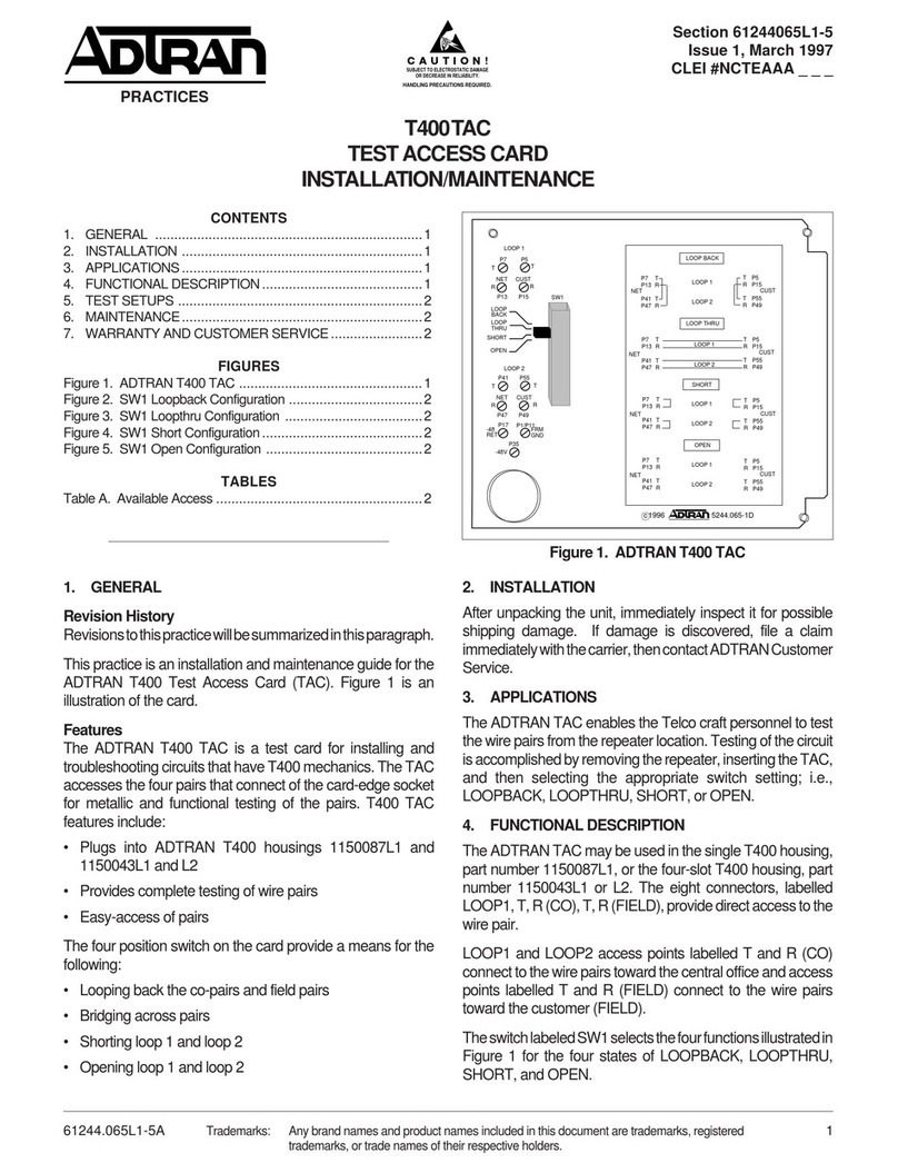
ADTRAN T400TAC Maintenance and service guide

ADTRAN

ADTRAN T400TAC Maintenance and service guide

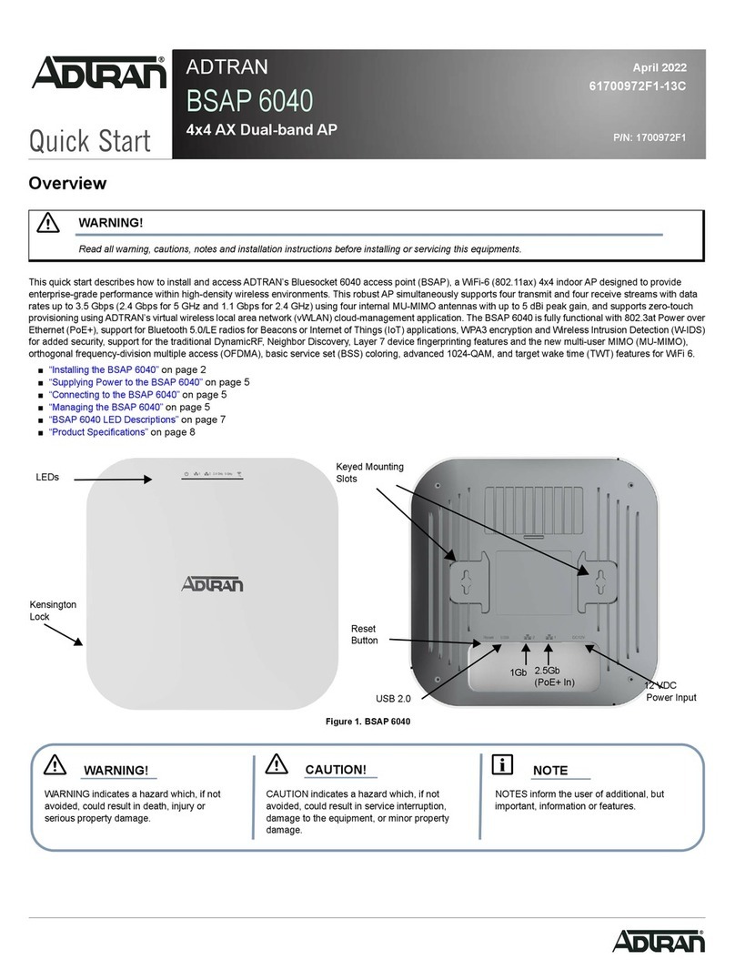
ADTRAN BSAP 6040 User manual

ADTRAN

ADTRAN BSAP 6040 User manual

ADTRAN SMART/RG SR506n User manual

ADTRAN

ADTRAN SMART/RG SR506n User manual

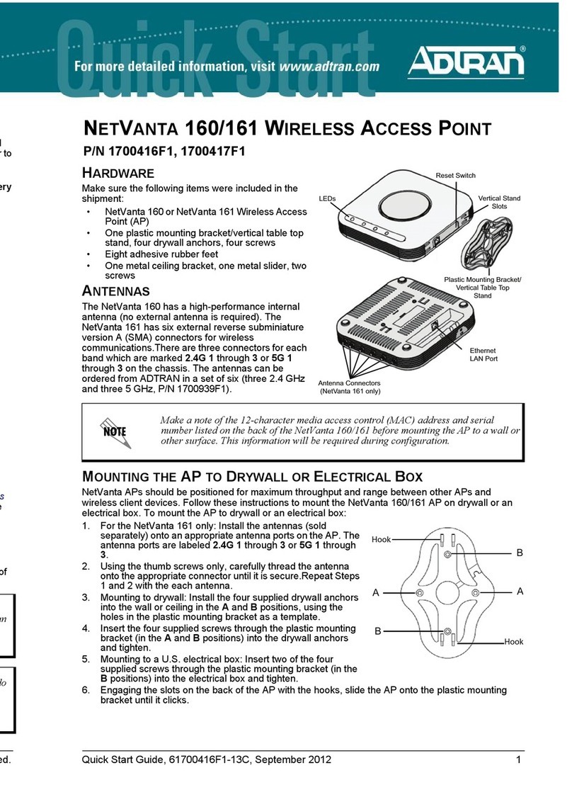
ADTRAN NetVanta 160 Installation instructions

ADTRAN

ADTRAN NetVanta 160 Installation instructions

ADTRAN 1287564G1 User manual

ADTRAN

ADTRAN 1287564G1 User manual

ADTRAN BLUESOCKET 1930 User manual

ADTRAN

ADTRAN BLUESOCKET 1930 User manual

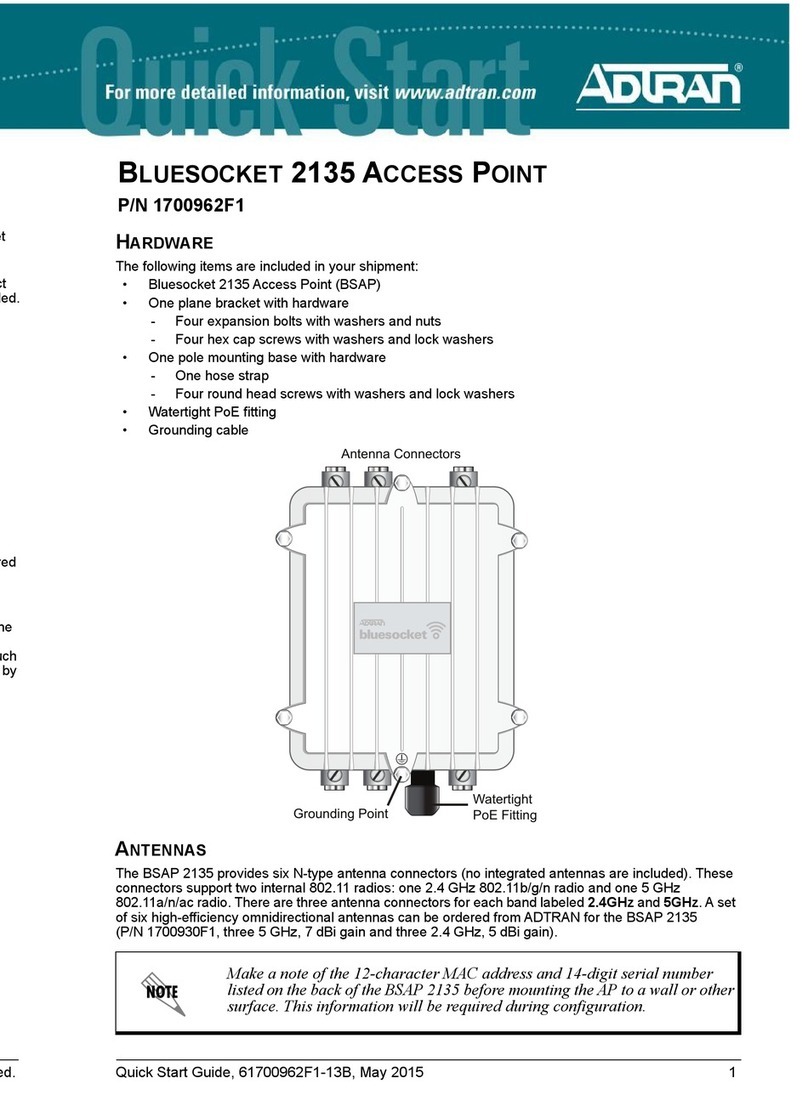
ADTRAN 2135 User manual

ADTRAN

ADTRAN 2135 User manual

ADTRAN NetVanta 160 User manual

ADTRAN

ADTRAN NetVanta 160 User manual
ADTRAN Bluesocket 3040 User manual

ADTRAN

ADTRAN Bluesocket 3040 User manual

ADTRAN NetVanta 150 User manual

ADTRAN

ADTRAN NetVanta 150 User manual

ADTRAN Bluesocket 2020 Series User manual

ADTRAN

ADTRAN Bluesocket 2020 Series User manual

ADTRAN NetVanta 100 Series Manual

ADTRAN

ADTRAN NetVanta 100 Series Manual

ADTRAN Total Access 612 User manual

ADTRAN

ADTRAN Total Access 612 User manual
ADTRAN NetVanta 150 Series Manual

ADTRAN

ADTRAN NetVanta 150 Series Manual

ADTRAN BLUESOCKET 2135 User manual

ADTRAN

ADTRAN BLUESOCKET 2135 User manual

ADTRAN BLUESOCKET 1940 User manual

ADTRAN

ADTRAN BLUESOCKET 1940 User manual

ADTRAN NetVanta 900 Series User manual

ADTRAN

ADTRAN NetVanta 900 Series User manual

ADTRAN BLUESOCKET 1920 User manual

ADTRAN

ADTRAN BLUESOCKET 1920 User manual

ADTRAN ATLAS 550 User manual

ADTRAN

ADTRAN ATLAS 550 User manual

ADTRAN BSAP 6120 User manual

ADTRAN

ADTRAN BSAP 6120 User manual
ADTRAN Total Access 5004 User manual

ADTRAN

ADTRAN Total Access 5004 User manual
Popular Wireless Access Point manuals by other brands

Planet Networking & Communication WNAP-6305 Quick installation guide

Planet Networking & Communication

Planet Networking & Communication WNAP-6305 Quick installation guide

Samsung WEA524i Quick installation manual

Samsung

Samsung WEA524i Quick installation manual

Cisco Linksys WAP610N user guide

Cisco

Cisco Linksys WAP610N user guide

Novatel MiFi2200 Product user guide

Novatel

Novatel MiFi2200 Product user guide

Hewlett Packard Enterprise Aruba 370 Series Startup guide

Hewlett Packard Enterprise

Hewlett Packard Enterprise Aruba 370 Series Startup guide

Edimax EW-7438RPn V2 Features

Edimax

Edimax EW-7438RPn V2 Features

Fortinet FortiAP 831F quick start guide

Fortinet

Fortinet FortiAP 831F quick start guide

Edimax EW-7416APn v2 Quick install guide

Edimax

Edimax EW-7416APn v2 Quick install guide

Enable-IT 8424 user manual

Enable-IT

Enable-IT 8424 user manual

Mist AP41 Hardware installation guide

Mist

Mist AP41 Hardware installation guide

Aruba 210 Series installation guide

Aruba

Aruba 210 Series installation guide

H3C 6W100 manual

H3C

H3C 6W100 manual

Cisco Meraki MR70 installation guide

Cisco

Cisco Meraki MR70 installation guide

SMC Networks EliteConnect SMC2555W-AG2 Specifications

SMC Networks

SMC Networks EliteConnect SMC2555W-AG2 Specifications

AirTies AP-301 user manual

AirTies

AirTies AP-301 user manual

ZyXEL Communications NWA-1100 datasheet

ZyXEL Communications

ZyXEL Communications NWA-1100 datasheet

Devolo Duo Specifications

Devolo

Devolo Duo Specifications

LXE 6250 Configuration guide

LXE

LXE 6250 Configuration guide

manuals.online logo
manuals.online logoBrands
  • About & Mission
  • Contact us
  • Privacy Policy
  • Terms and Conditions

Copyright 2025 Manuals.Online. All Rights Reserved.