manuals.online logo
Brands
  1. Home
  2. •
  3. Brands
  4. •
  5. ADTRAN
  6. •
  7. Wireless Access Point
  8. •
  9. ADTRAN NetVanta 900 Series User manual

ADTRAN NetVanta 900 Series User manual

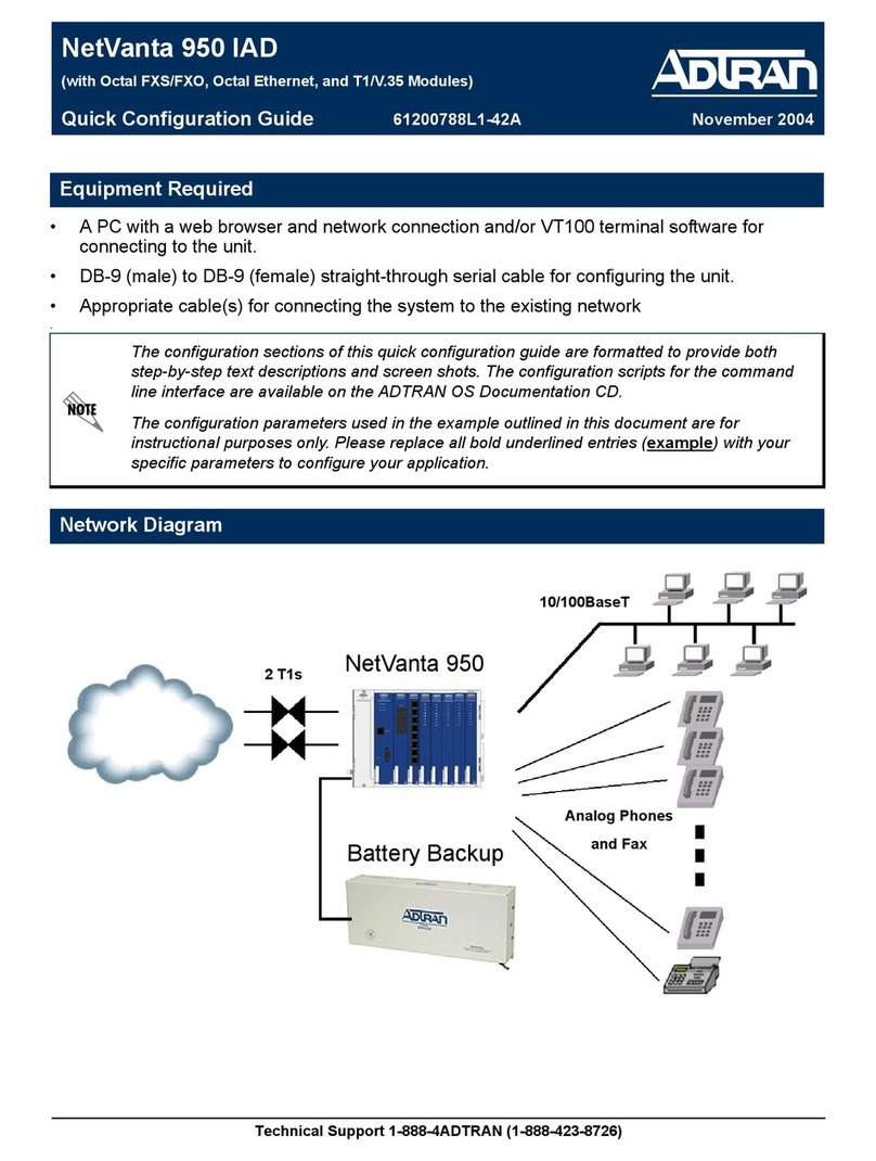
61200788L1-29.1B
July 2004
Configuration Guide
Configuration Guide: Analog and
Digital Voice
This Configuration Guide is designed to provide you with a basic
understanding of the concepts behind configuring your NetVanta 950 IAD
for analog and digital voice traffic. Two configuration methods are
available for your NetVanta IAD:
• Web-Based GUI
• AOS CLI
The web-based GUI lets you configure the main settings and provides
online guidance and explanations for each setting. However, use of the
AOS CLI may be necessary for more advanced configurations.
Access the AOS CLI via the CONSOLE port or a Telnet session. For more
details on CLI access, refer to the AOS Command Reference Guide on
your ADTRAN OS Documentation CD (included in the shipment).
This guide consists of the following sections:
•Understanding Analog and Digital Voice on page 2
•Configuring Your IAD on page 4
•Verifying Your Configuration Using Show Commands on page 36
•Testing Your System on page 38
•Managing Event Messages on page 41
Understanding Analog and Digital Voice NetVanta 950 IAD Configuration Guide
2 © 2004 ADTRAN, Inc. 61200788L1-29.1B
1. UNDERSTANDING ANALOG AND DIGITAL VOICE
Hardware Description
The applications discussed in this guide require the following hardware:
• One NetVanta 900 Series AC Chassis (P/N 1200786L1)
• One NetVanta 950 IAD Controller (P/N 1200788L1)
• One NetVanta 950 T1/V.35 Expansion Module (P/N 1200798L1)
• Five NetVanta 900 Series Octal FXS Access Modules (P/N 1200791L1)
• One NetVanta 900 Series Octal FXO Access Module (P/N 1200792L1)
Figure 1 shows the front view of the chassis.
Figure 1. NetVanta 950 IAD Front Panel Layout
The CONSOLE port and T1 1/1 port are located on the front of the unit. The LEDs on the Controller, T1/V.35
Expansion Module, FXO Access Module, and FXS Access modules provide status information.
1200792L11200792L1
NetVanta 900 Series
ANLG FXO
1200792L1
TRUNKS
NetVanta 950 IAD Configuration Guide Understanding Analog and Digital Voice
61200788L1-29.1B © 2004 ADTRAN, Inc. 3
The tip/ring pairs for the analog voice ports connect to the right side of the chassis shown in Figure 2.
Figure 2. NetVanta 950 IAD Right Side Panel Layout
The T1s connect to the left side of the chassis as shown in Figure 3.
Figure 3. NetVanta 950 IAD Left Side Panel Layout
Voice Ports
(Amphenol)
T1
Network
Connections
Alarm
Contacts
Battery
Backup
Connection
Ground
Lug
Power
Connection
Configuring Your IAD NetVanta 950 IAD Configuration Guide
4 © 2004 ADTRAN, Inc. 61200788L1-29.1B
Common Applications
• POTS to PSTN via T1 - less expensive than individual analog trunk lines
• POTS to Centrex service via T1
• PBX to PSTN via T1 or FXO
•OPX
Types of Signaling
• Analog: Loop Start, Ground Start, E&M, DPT (FXO only)
• Digital: Robbed-Bit, Clear Channel
2. CONFIGURING YOUR IAD
The remainder of this document provides examples designed to clarify the configuration of analog (FXS or
FXO) or digital (T1) voice. Section 2a describes how to configure the IAD with the Web GUI. Section 2b
(starting on page 16) describes how to configure the IAD with the CLI.
2a. Configuring your IAD with the Web GUI
You can configure your IAD with the interactive Web GUI. The web-based GUI lets you configure the
main settings and provides online guidance and explanations for each setting. However, you may have to
use the AOS CLI for more advanced configurations.
Logging In
Open a browser window and type the IP address for the unit in the address field. A login window
(shown in Figure 4) displays.
Figure 4. Login Screen
Enter your USER NAME and PASSWORD; then click OK. The default username is admin, and the default
password is password. The IAD MANAGEMENT INTERFACE for the NetVanta 950 displays as shown in
Figure 5 on page 5. For information on setting your IP address and connecting the IAD to the LAN,
refer to the NetVanta 950 IAD Quick Configuration Guide provided on your ADTRAN OS
Documentation CD.
NetVanta 950 IAD Configuration Guide Configuring Your IAD
61200788L1-29.1B © 2004 ADTRAN, Inc. 5
T1 Ports
When you log into the Web GUI, the GENERAL SYSTEM INFORMATION page displays in your browser
window.
Figure 5. General System Information Page
Configuring Your IAD NetVanta 950 IAD Configuration Guide
6 © 2004 ADTRAN, Inc. 61200788L1-29.1B
In the left column select PHYSICAL INTERFACES, and the screen shown in Figure 6 displays. This
screen shows all the physical interfaces that are installed in the system.
Figure 6. Physical Interfaces Page
NetVanta 950 IAD Configuration Guide Configuring Your IAD
61200788L1-29.1B © 2004 ADTRAN, Inc. 7
View or edit the configuration of an interface by selecting its name. Select the t1 0/1 port, and
the T1 0/1 CONFIGURATION page displays as shown in Figure 7.
Figure 7. Configuration for T1 0/1
By default, the T1 interface is set for ESF framing and B8ZS coding. If you want to change settings,
select different options from the pulldown menus. For example, if you want to change FRAMING, select
the pulldown menu as shown in Figure 8. Select the new option from the list. When you are finished
making changes, select APPLY.
Figure 8. Changing the Framing Configuration
Configuring Your IAD NetVanta 950 IAD Configuration Guide
8 © 2004 ADTRAN, Inc. 61200788L1-29.1B
System Clock Source
The clock source provides the reference point for all voice and data traffic in the system. There can
only be one clock source for the system, otherwise clock slips may occur on the other T1 interfaces,
resulting in noise on voice lines and errors on data circuits. Options include INTERNAL, t1 0/1, or t1 0/2.
The default clock source is t1 0/1. Change the clock source by clicking on the PRIMARY CLOCK SOURCE
menu and selecting another option. You can also select a backup source if more than one source exists;
otherwise, Internal timing will be used as a backup. When you are finished making changes, click
APPLY.
Figure 9. System Clock Source
You can also check the configured settings as well as the current clock source on the
GENERAL SYSTEM INFORMATION page as shown in Figure 5 on page 5.
NetVanta 950 IAD Configuration Guide Configuring Your IAD
61200788L1-29.1B © 2004 ADTRAN, Inc. 9
TDM Groups
TDM groups are used to assign a number of DS0s to a particular interface. By creating a TDM group,
the user sets aside a block of T1 channels for use in a particular cross connect. To access the DS0
Connections, scroll down the browser screen until you see the configuration box shown below. You
can assign 24 DS0s to a T1 interface by selecting a DS0 RANGE of 1 to 24 (as shown in Figure 10). For
the CONNECT TOfield, select t1 0/1. For the STARTING DS0 select 1. Click ADD. A TDM group is
created for the interface and channels 1-24 are assigned to the TDM group. The new DS0 connection
displays at the bottom of the box.
Figure 10. TDM Groups
You can scroll down the page and use the STATUS box to view a snapshot of the current
status and statistics or to get a continuous update of the status and statistics of the T1 port.
Configuring Your IAD NetVanta 950 IAD Configuration Guide
10 © 2004 ADTRAN, Inc. 61200788L1-29.1B
Configuring the FXS Card
To configure the FXS card, select PHYSICAL INTERFACES in the left pane. All of the available interfaces
display as shown in Figure 6 on page 6. Select an FXS port, such as fxs 7/1,and the page shown in
Figure 11 displays. Change any of the settings (discussed in detail below) as required. When you are
finished, select APPLY. To apply changes to several ports at the same time, select the check box for each
port at the top of the screen. To apply the changes to all of the ports, click SELECT ROW.
Figure 11. FXS Card Configuration Settings
Settings
Click on ENABLE to enable the interface. The interface is disabled by default. The receive gain is
configurable in 0.1 dB increments from -12 dB to +6 dB (default is -3 dB). Receive gain determines
the amplification of the signal before sending the signal out the FXS interface. When increasing this
value, the signal being received on this port from the network sounds louder. When decreasing this
value, the signal being received on this port sounds softer.
The transmit gain is also configurable in 0.1 dB increments from -12 dB to +6 dB (default is -6 dB).
Transmit gain determines the amplification of the signal before sending the signal towards the
network. When increasing this value, the signal being transmitted to the far end sounds louder. When
decreasing this value, the signal being transmitted to the far end sounds softer.
NetVanta 950 IAD Configuration Guide Configuring Your IAD
61200788L1-29.1B © 2004 ADTRAN, Inc. 11
To change impedance, click the pulldown menu to select the appropriate terminating impedance for the
interface. There are four possible impedance settings: 600 OHM,600 OHM + 2.16UF, 900 OHM, and 900
OHM +2.16UF.
Answer Supervision configures answer supervision for the appropriate voice port(s). Answer
supervision (when the far end answers the call) is indicated by using reverse battery polarity. Enabling
this option will cause the FXS interface to interpret reverse battery polarity on the 2-wire interface as
LSAS (Line Side Answer Supervision) and transmit the appropriate signaling bits on the T1. The
LSAS signaling is defined as 0100 (for ESF) or 01/00 (for D4). The carrier must configure the network
T1 for LSAS (if this is not a point-to-point T1).
Signaling
Loop start signaling bridges tip and ring to indicate an off-hook (seizing the line) condition. Ground
start signaling applies resistance to the tip conductor of the circuit to indicate an off-hook (seizing the
line) condition. The signaling mode must match the configuration of the network and the expected
operation with customer premise equipment. The FXS ports are set for loop start signaling by default.
You can scroll down the page and use the STATUS box to view a snapshot of the current
status and statistics or to get a continuous update of the status and statistics of the FXS
port.
Configuring Your IAD NetVanta 950 IAD Configuration Guide
12 © 2004 ADTRAN, Inc. 61200788L1-29.1B
Configuring the FXO Card
To configure the FXO card, select PHYSICAL INTERFACES in the left pane. All of the available interfaces
display as shown in Figure 6 on page 6. Select an FXO port, such as fxo 6/1,and the page shown in
Figure 12 displays. Change any of the settings (discussed in detail below) as required. When you are
done editing, select APPLY. To apply changes to several ports at the same time, select the check box for
each port at the top of the screen. To apply the changes to all of the ports, click SELECT ROW.
Figure 12. FXO Card Configuration Settings
Settings
Click on ENABLE to enable the interface. The interface is disabled by default. The receive gain is
configurable in 0.1 dB increments from -12 dB to +6 dB (default is -0 dB). Receive gain determines
the amplification of the signal before sending the signal out the FXO interface. When increasing this
value, the signal being received on this port from the network sounds louder. When decreasing this
value, the signal being received on this port sounds softer.
The transmit gain is also configurable in 0.1 dB increments from -12 dB to +6 dB (default is -0 dB).
Transmit gain determines the amplification of the signal before sending the signal towards the
network. When increasing this value, the signal being transmitted to the far end sounds louder. When
decreasing this value, the signal being transmitted to the far end sounds softer.
NetVanta 950 IAD Configuration Guide Configuring Your IAD
61200788L1-29.1B © 2004 ADTRAN, Inc. 13
To change impedance, click the pulldown menu to select the appropriate terminating impedance for the
interface. There are two possible impedance settings: 600 OHM +2.16UFand 900 OHM +2.16UF.
Answer Supervision configures answer supervision for the appropriate voice port(s). Answer
supervision (when the far end answers the call) is indicated by using reverse battery polarity. Enabling
this option will cause the FXO interface to interpret reverse battery polarity on the 2-wire interface as
LSAS (Line Side Answer Supervision) and transmit the appropriate signaling bits on the T1. The
LSAS signaling is defined as 0100 (for ESF) or 01/00 (for D4). The carrier must configure the network
T1 for LSAS (if this is not a point-to-point T1).
Signaling
Loop start signaling bridges tip and ring to indicate an off-hook (seizing the line) condition. Ground
start signaling applies resistance to the tip conductor of the circuit to indicate an off-hook (seizing the
line) condition. DPT signaling is used when connecting the FXO interface to analog DPO ports on the
customer premise equipment. The signaling mode must match the configuration of the network and the
expected operation with customer premises equipment. The FXO ports are set for loop start signaling
by default.
You can scroll down the page and use the STATUS box to view a snapshot of the current
status and statistics or to get a continuous update of the status and statistics of the FXO
port.
Configuring Your IAD NetVanta 950 IAD Configuration Guide
14 © 2004 ADTRAN, Inc. 61200788L1-29.1B
Analog Ports
The ANALOG PORTS page (Figure 13) shows the analog ports in the system. This is a subset of the
PHYSICAL INTERFACES page. From here, you can go to the individual port page for configuration just as
you did from the PHYSICAL INTERFACES page. See Figure 11 on page 10 and Figure 12 on page 12.
Figure 13. Analog Ports Summary Page
NetVanta 950 IAD Configuration Guide Configuring Your IAD
61200788L1-29.1B © 2004 ADTRAN, Inc. 15
Connections
The CONNECTIONS SUMMARY page (Figure 14) shows every TDM connection in the system. You can go
to the individual port page for configuration just as instructed for the PHYSICAL INTERFACES page.
Figure 14. Connections Page
Configuring Your IAD NetVanta 950 IAD Configuration Guide
16 © 2004 ADTRAN, Inc. 61200788L1-29.1B
Saving Your Configuration
At the top of each page there are SAVE and LOGOUT links. To save your configuration, either select
SAVE at the top of the page or select the CONFIGURATION option in the left column. The page shown in
Figure 15 displays. From this page you can save your current configuration, download the
configuration from the IAD to your PC, or upload a new configuration to the IAD. When you are
finished, select LOGOUT at the top of the page to log out of the Web GUI.
Figure 15. Save Configuration Page
2b. Configuring Your IAD with the CLI
This section describes how to configure the NetVanta 950 using the CLI. The following sections (T1 Ports,
Voice Ports, and Connecting Interfaces) give an overview of the options and steps necessary when
configuring analog or digital voice. See Configuration Examples on page 22 for additional information.
NetVanta 950 IAD Configuration Guide Configuring Your IAD
61200788L1-29.1B © 2004 ADTRAN, Inc. 17
T1 Ports
From the prompt, IAD#, enter configure terminal. All interfaces will be configured from within the
configure terminal mode. Enter interface t1 0/1 to configure the controller’s first T1 port (0/1).
Settings
The T1 interface is set for B8ZS coding, ESF framing, and 0 dB line build out (LBO) by default. If the
user wanted to change coding, for example, typing coding ami would configure the T1 port for AMI
coding. For framing, type framing d4 to configure the interface for D4 framing. The IAD supports
four different settings for Line Build Out. Type lbo -22.5 to set the Line Build out to -22.5 dB. Other
settings include -15 and -7.5. See the AOS Command Reference Guide for a complete list of all T1
commands, or type ? at the prompt.
TDM Groups
TDM groups are used to assign a number of DS0s to a particular interface. By creating a TDM group,
the user sets aside a block of T1 channels for use in a particular cross connect. You can assign 24 DS0s
to a T1 interface by typing tdm-group 1 timeslots 1-24. This command creates TDM group 1 for the
interface ("one" was chosen arbitrarily; it could be any value between 1 and 255) and assigns channels
1-24 to it.
Activation
The last step of the T1 interface configuration is to activate the T1 interfaces by typing no shutdown
from the IAD (config-t1 0/1)# prompt for T1 WAN 0/1 or the IAD (config-t1 0/2)# prompt for T1
WA N 0 / 2 . S e e Verifying Your Configuration Using Show Commands on page 36 section for more
information on the status of the T1 port.
Clock Source
The clock source provides the reference point for all voice and data traffic in the system. There can
only be one active clock source for the system; otherwise clock slips may occur on the other T1
interfaces resulting in noise on voice lines and errors on data circuits. Options include internal, t1 0/1,
or t1 0/2. The default clock source is t1 0/1. For example, type clock source t1 0/2 to set the timing
source to the controller's second T1 port. The system also allows a secondary clock source for backup
timing. In the event of a failure of the primary source, the system switches over to the secondary
source. To configure T1 0/1 as a secondary timing source, type clock source t1 0/1 secondary.
Voice Ports (FXS)
From the prompt, IAD#, enter configure terminal. All interfaces will be configured from within the
configure terminal mode. Enter interface fxs 2/1 to configure the first FXS port on the access module
in slot 2.
The user may configure each port one at a time or use the range command to set a group of ports at the
same time. To use the range command, type interface range fxs slot x/port a-b, fxs slot y/port a-b
where slot x and y are slots with FXS cards installed and port a-b specifies the range of ports to be
configured. For example, to configure FXS slot 3, ports 1-8 and FXS slot 5, ports 1-4, from the Global
configuration prompt, type interface range fxs 3/1-8, fxs 5/1-4. Then type the desired command to
configure all 12 of the specified ports identically.
Configuring Your IAD NetVanta 950 IAD Configuration Guide
18 © 2004 ADTRAN, Inc. 61200788L1-29.1B
For additional information about the available settings for the FXS card, see Configuring the FXS Card
on page 10.
All other interface configuration options are dependent on the type of signaling used. These settings
are described in the Signaling section. See the AOS Command Reference Guide for a complete list of
all FXS commands, or type ?at the prompt.
Signaling
Loop start signaling bridges tip and ring to indicate an off-hook (seizing the line) condition. Ground
start signaling applies resistance to the tip conductor of the circuit to indicate an off-hook (seizing the
line) condition. The signaling mode must match the configuration of the network and the expected
operation with customer premises equipment. The FXS ports are set for loop start signaling by default.
The other option is ground start signaling. To change the signaling type to ground start, type signal
ground-start.
E&M Tandem conversion is a setting used to convert E&M signaling on a T1 to FXS loop start or
ground start signaling. The em-conversion command has two possible settings, immediate and wink.
Type em-conversion immediate to transmit DTMF digits toward the 2-wire interface immediately
following an off-hook condition. Type em-conversion wink to implement a wink process for inbound
calls. Use the no command to disable em-conversion (em-conversion is disabled by default).
There are several other settings that are only valid if E&M Conversion is enabled. These include
dial-tone, dnis-delay, dnis-wink-timeout, forward-disconnect delay, forward-disconnect battery,
and ringback. Type dial-tone to enable dial-tone and type ringback to enable ringback. They should
be enabled whenever the central office switch does not provide those features. They are only necessary
in E&M applications and em-conversion must be configured.
The dnis-delay and dnis-wink-timeout commands are used in conjunction with the em-conversion
wink setting. Use dnis-delay to define the time delay after transmitting a wink in response to the
2-wire interface going off-hook (after ringing) before transmitting off-hook towards the T1 interface.
Dnis-delay is only valid when em-conversion is configured for wink. By default, dnis-delay is
disabled. The no version of this command disables dnis-delay. Possible settings range from 500 ms to
3000 ms in 500 ms increments. For example, type dnis-delay 1500 to set the delay to 1.5 seconds.
When dnis-delay is specified and dnis-wink-timeout is enabled, a wink is returned to the originating
switch after five seconds if the port does not detect an off-hook condition. Disabling this option allows
the FXS port to ring without winking until the call is answered. By default this option is enabled when
dnis-delay is activated.
.
Finally, forward-disconnect delay and forward-disconnect battery are used together to define the
actions of the FXS port when the remote equipment ends the call. Both commands are disabled by
default and are only used when the interface is configured for loop-start and em-conversion is
enabled. The forward-disconnect delay specifies the number of milliseconds the FXS module waits
after initiating a disconnect sequence on the FXS interface as a result of remote end terminating the
call, before returning to an idle condition. By default, forward-disconnect delay is disabled. If
Trunks may be taken out of service by the central office switch if no wink is received. Use
caution when disabling this option.
NetVanta 950 IAD Configuration Guide Configuring Your IAD
61200788L1-29.1B © 2004 ADTRAN, Inc. 19
configured, the recommended initial setting is 1000 ms. Possible settings are 250, 500, 750, 1000, and
2000 ms.
Use forward-disconnect battery to specify the behavior of the battery when the remote equipment
ends the call. Possible settings are remove and reverse. Selecting remove configures the FXS to
remove battery from the circuit when the remote equipment ends the call. Selecting reverse configures
the FXS to reverse battery polarity on the circuit when the remote equipment ends the call. By default,
forward-disconnect battery is disabled. Setting forward-disconnect battery is only necessary when
em-conversion is configured and a forward-disconnect delay specified. If configured, the
recommended initial setting is forward-disconnect battery remove.
TDM Groups
An FXS port can only connect to a single DS0, so there are no TDM groups for FXS ports. FXS ports
are assigned to DS0s using the cross-connect command discussed in Connecting the Interfaces on
page 21.
Activation
The user may activate each port individually, or if the range command is used many ports can be
activated simultaneously. To activate each port one at a time, first enter interface fxs 2/1 from the
Global configuration mode. Type no shutdown. Then type interface fxs 2/2 to move to the next port
and repeat through interface fxs 6/8.
To activate all the ports with the range command, type interface range fxs 2/1-8,fxs 3/1-8, fxs 4/1-8,
fxs 5/1-8, fxs 6/1-8 and then type no shutdown.
See Verifying Your Configuration Using Show Commands on page 36 for more information on the
status of each FXS port.
Voice Ports (FXO)
From the prompt, IAD#, enter configure terminal. All interfaces will be configured from within the
configure terminal mode. Enter interface fxo 7/1 to configure the first FXO port on the access module
in slot 7.
The user may configure each port one at a time or use the range command to set a group of ports at the
same time. To use the range command, type interface range fxo slot x/port a-b, fxo slot y/port a-b
where slot x and y are slots with FXO cards installed and port a-b specifies the range of ports to be
configured. For example, to configure FXO slot 3, ports 1-8 and FXO slot 5, ports 1-4, from the Global
configuration prompt, type interface range fxo 3/1-8, fxo 5/1-4. Then type the desired command to
configure all 12 of the specified ports identically.
Making configuration changes while a port is active will cause the call to drop.
Configuring Your IAD NetVanta 950 IAD Configuration Guide
20 © 2004 ADTRAN, Inc. 61200788L1-29.1B
Settings
Each FXO interface is set for Loop Start signaling, 600Ω + 2.16uF impedance, answer supervision
disabled and with receive and transmit gains both set to 0 dB. If, for example, the user wanted to
change impedance, typing impedance 600c would configure the FXO port for 600Ω+2.16uF
impedance. There are two possible impedance settings: 600c (600 Ω+2.16uF complex) and 900c (900
Ω+2.16uF complex).
Answer Supervision enables answer supervision for the FXO port. Answer supervision (when the far
end answers the call) is indicated by using reverse battery polarity. Enabling this option will cause the
FXO interface to interpret reverse battery polarity on the 2-wire interface as LSAS (Line Side Answer
Supervision) and transmit the appropriate signaling bits on the T1. The LSAS signaling is defined as
0100 (for ESF) or 01/00 (for D4). The carrier must configure the network T1 for LSAS (if this is not a
point-to-point T1).
The receive gain is configurable in 0.1 dB increments from -6 dB to +10 dB (default is 0 dB). Receive
gain determines the amplification of the signal before sending the signal out the FXO interface. When
increasing this value, the signal being received on this port from the network sounds louder. When
decreasing this value, the signal being received on this port sounds softer. Type rx-gain -10 to set the
receive gain to –10 dB, for example.
The transmit gain is also configurable in 0.1 dB increments from -6 dB to +10 dB (default is 0 dB).
Transmit gain determines the amplification of the signal before sending the signal towards the
network. When increasing this value, the signal being transmitted to the far end sounds louder. When
decreasing this value, the signal being transmitted to the far end sounds softer. Type tx-gain 4.8 to set
the transmit gain to +4.8 dB, for example.
See the AOS Command Reference Guide for a complete list of all FXO commands, or type ?at the
prompt.
Signaling
The FXO supports three types of signalling: Loop Start, Ground Start, and DPT. Loop start signaling
bridges tip and ring to indicate an off-hook (seizing the line) condition. Ground start signaling applies
resistance to the tip conductor of the circuit to indicate an off-hook (seizing the line) condition. DPT
signaling is used when connecting the FXO interface to analog DPO ports on the customer premise
equipment. The signaling mode must match the configuration of the network and the expected
operation with customer premises equipment. The FXO ports are set for loop start signaling by default.
To change the signaling type to ground start, type signal ground-start, for example.
TDM Groups
An FXO port can only connect to a single DS0, so there are no TDM groups for FXO ports. FXO ports
are assigned to DS0s using the cross-connect command discussed in Connecting the Interfaces on
page 21.
Making configuration changes while a port is active will cause the call to drop.

Other manuals for NetVanta 900 Series

2

This manual suits for next models

1

Other ADTRAN Wireless Access Point manuals
ADTRAN NetVanta 2054 User manual

ADTRAN

ADTRAN NetVanta 2054 User manual

ADTRAN T400TAC Maintenance and service guide

ADTRAN

ADTRAN T400TAC Maintenance and service guide

ADTRAN Bluesocket 2020 Series User manual

ADTRAN

ADTRAN Bluesocket 2020 Series User manual

ADTRAN 1287564G1 User manual

ADTRAN

ADTRAN 1287564G1 User manual

ADTRAN BSAP 6040 User manual

ADTRAN

ADTRAN BSAP 6040 User manual

ADTRAN BlueSocket BSAP 1920 User manual

ADTRAN

ADTRAN BlueSocket BSAP 1920 User manual

ADTRAN NetVanta 150 User manual

ADTRAN

ADTRAN NetVanta 150 User manual

ADTRAN NetVanta 150 Series Manual

ADTRAN

ADTRAN NetVanta 150 Series Manual

ADTRAN NetVanta 160 Installation instructions

ADTRAN

ADTRAN NetVanta 160 Installation instructions

ADTRAN BLUESOCKET 2135 User manual

ADTRAN

ADTRAN BLUESOCKET 2135 User manual

ADTRAN Total Access 850 Instruction Manual

ADTRAN

ADTRAN Total Access 850 Instruction Manual

ADTRAN 2135 User manual

ADTRAN

ADTRAN 2135 User manual

ADTRAN BLUESOCKET 1940 User manual

ADTRAN

ADTRAN BLUESOCKET 1940 User manual

ADTRAN Bluesocket 2020 Series User manual

ADTRAN

ADTRAN Bluesocket 2020 Series User manual

ADTRAN BLUESOCKET 1930 User manual

ADTRAN

ADTRAN BLUESOCKET 1930 User manual

ADTRAN Bluesocket 2030 User manual

ADTRAN

ADTRAN Bluesocket 2030 User manual

ADTRAN BLUESOCKET 3045 User manual

ADTRAN

ADTRAN BLUESOCKET 3045 User manual

ADTRAN NetVanta 160 User manual

ADTRAN

ADTRAN NetVanta 160 User manual
ADTRAN 1700412E1 User manual

ADTRAN

ADTRAN 1700412E1 User manual

ADTRAN Total Access 5004 User manual

ADTRAN

ADTRAN Total Access 5004 User manual
ADTRAN BSAP 6120 User manual

ADTRAN

ADTRAN BSAP 6120 User manual
ADTRAN NetVanta 950 IAD User manual

ADTRAN

ADTRAN NetVanta 950 IAD User manual
ADTRAN NetVanta 100 Series Manual

ADTRAN

ADTRAN NetVanta 100 Series Manual

ADTRAN Total Access 612 User manual

ADTRAN

ADTRAN Total Access 612 User manual

Popular Wireless Access Point manuals by other brands

Planet Networking & Communication WNAP-6305 Quick installation guide

Planet Networking & Communication

Planet Networking & Communication WNAP-6305 Quick installation guide

Samsung WEA524i Quick installation manual

Samsung

Samsung WEA524i Quick installation manual

Cisco Linksys WAP610N user guide

Cisco

Cisco Linksys WAP610N user guide

Novatel MiFi2200 Product user guide

Novatel

Novatel MiFi2200 Product user guide

Hewlett Packard Enterprise Aruba 370 Series Startup guide

Hewlett Packard Enterprise

Hewlett Packard Enterprise Aruba 370 Series Startup guide

Edimax EW-7438RPn V2 Features

Edimax

Edimax EW-7438RPn V2 Features

Fortinet FortiAP 831F quick start guide

Fortinet

Fortinet FortiAP 831F quick start guide

Edimax EW-7416APn v2 Quick install guide

Edimax

Edimax EW-7416APn v2 Quick install guide

Enable-IT 8424 user manual

Enable-IT

Enable-IT 8424 user manual

Mist AP41 Hardware installation guide

Mist

Mist AP41 Hardware installation guide

Aruba 210 Series installation guide

Aruba

Aruba 210 Series installation guide

H3C 6W100 manual

H3C

H3C 6W100 manual

Cisco Meraki MR70 installation guide

Cisco

Cisco Meraki MR70 installation guide

SMC Networks EliteConnect SMC2555W-AG2 Specifications

SMC Networks

SMC Networks EliteConnect SMC2555W-AG2 Specifications

AirTies AP-301 user manual

AirTies

AirTies AP-301 user manual

ZyXEL Communications NWA-1100 datasheet

ZyXEL Communications

ZyXEL Communications NWA-1100 datasheet

Devolo Duo Specifications

Devolo

Devolo Duo Specifications

LXE 6250 Configuration guide

LXE

LXE 6250 Configuration guide

manuals.online logo
manuals.online logoBrands
  • About & Mission
  • Contact us
  • Privacy Policy
  • Terms and Conditions

Copyright 2025 Manuals.Online. All Rights Reserved.