Advance acoustic Proterra LPG User manual

Electronic Service
Manuals
This electronic document is provided as a service to our customers.
Wedonotcreatethecontentsoftheinformationcontainedinthisdocu-
ment. Shouldyouhavedetailedquestionspertainingtotheinformation
contained in this document, you may contact Michco, or the manufac-
turer which provided the original information in this electronic deliver-
able. Michco’sonlypartin this electronic deliverable was the electronic
assemblyprocess. Byprovidingthismanualonlinewearenotguaran-
teeing parts availability.
You may contact Michco through the following methods:
Phone (517) 484-9312 or (800) 331-3339
2011 N. High St. -- Lansing, Michigan -- 48906
Fax: (517) 484-9836
Email: [email protected]
Web site: www.Michco.Com
Parts Web site: www.FloorMachineParts.Com
Order Parts on Line at:
www.FloorMachineParts.Com
Directly to Parts & Service:
By Fax: (517) 702-2041
By Voice: Use numbers above.
Serving the Cleaning Industry Since 1922
Notice: All copyrighted material remains property of original owners, all trademarks are property of respective owners.
ManualsaresubjecttoManufacturer’sreproductionlimitations. Originalsorreproductionswereprovidedbymanufacturers
through a request. We make no warranty as to the correctness of information provided in this document and you assume
allrisk. By placing thesemanualsonlinewe are notdeclaringourcorporation to be anmanufacturerauthorizeddealer or
provider, please check ourwebsiteforauthorizedmanufacturerswerepresent.

Proterra™
INSTRUCTION FOR USE
INSTRUCTIONS D’UTILISATION
INSTRUCCIONES DE USO
INSTRUÇÕES DE USO
Advance models: 13300109 - 13300174
ENGLISH
FRANÇAIS
ESPAÑOL
PORTUGUÊS
33019864(3)2012-03
33019864(3)2012-03.indb 1 16/04/2012 12:40:49

33019864(3)2012-03.indb 2 16/04/2012 12:40:49

INSTRUCTION FOR USE ENGLISH
33019864 - Proterra™ 1
TABLE OF CONTENTS
INTRODUCTION.............................................................................................................................................................. 2
MANUAL PURPOSE AND CONTENTS .......................................................................................................................................... 2
TARGET........................................................................................................................................................................................... 2
HOW TO STORE THIS MANUAL.................................................................................................................................................... 2
IDENTIFICATION DATA................................................................................................................................................................... 2
OTHER REFERENCE MANUALS................................................................................................................................................... 2
SPARE PARTS AND MAINTENANCE............................................................................................................................................. 2
CHANGES AND IMPROVEMENTS ................................................................................................................................................ 2
OPERATION CAPABILITIES ........................................................................................................................................................... 3
CONVENTIONS .............................................................................................................................................................................. 3
UNPACKING/DELIVERY ................................................................................................................................................. 3
SAFETY ........................................................................................................................................................................... 3
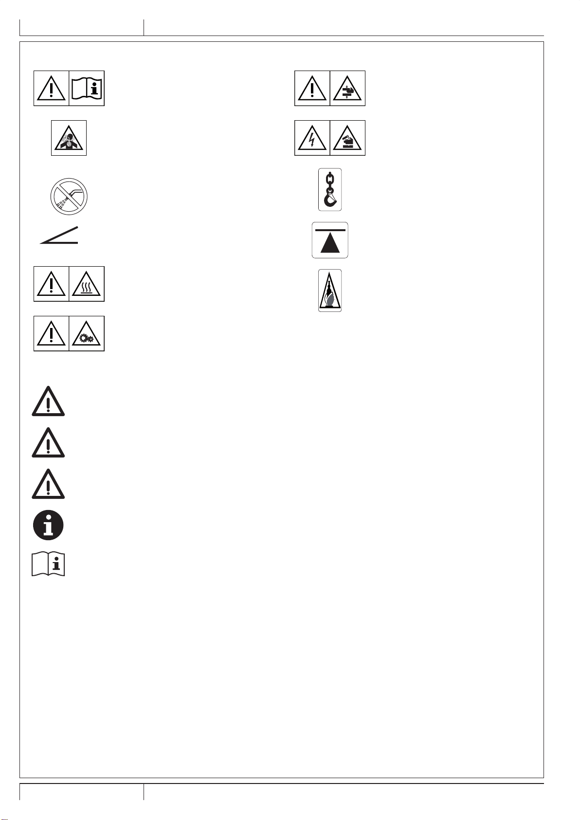
VISIBLE SYMBOLS ON THE MACHINE......................................................................................................................................... 4
SYMBOLS THAT APPEAR ON THIS MANUAL............................................................................................................................... 4
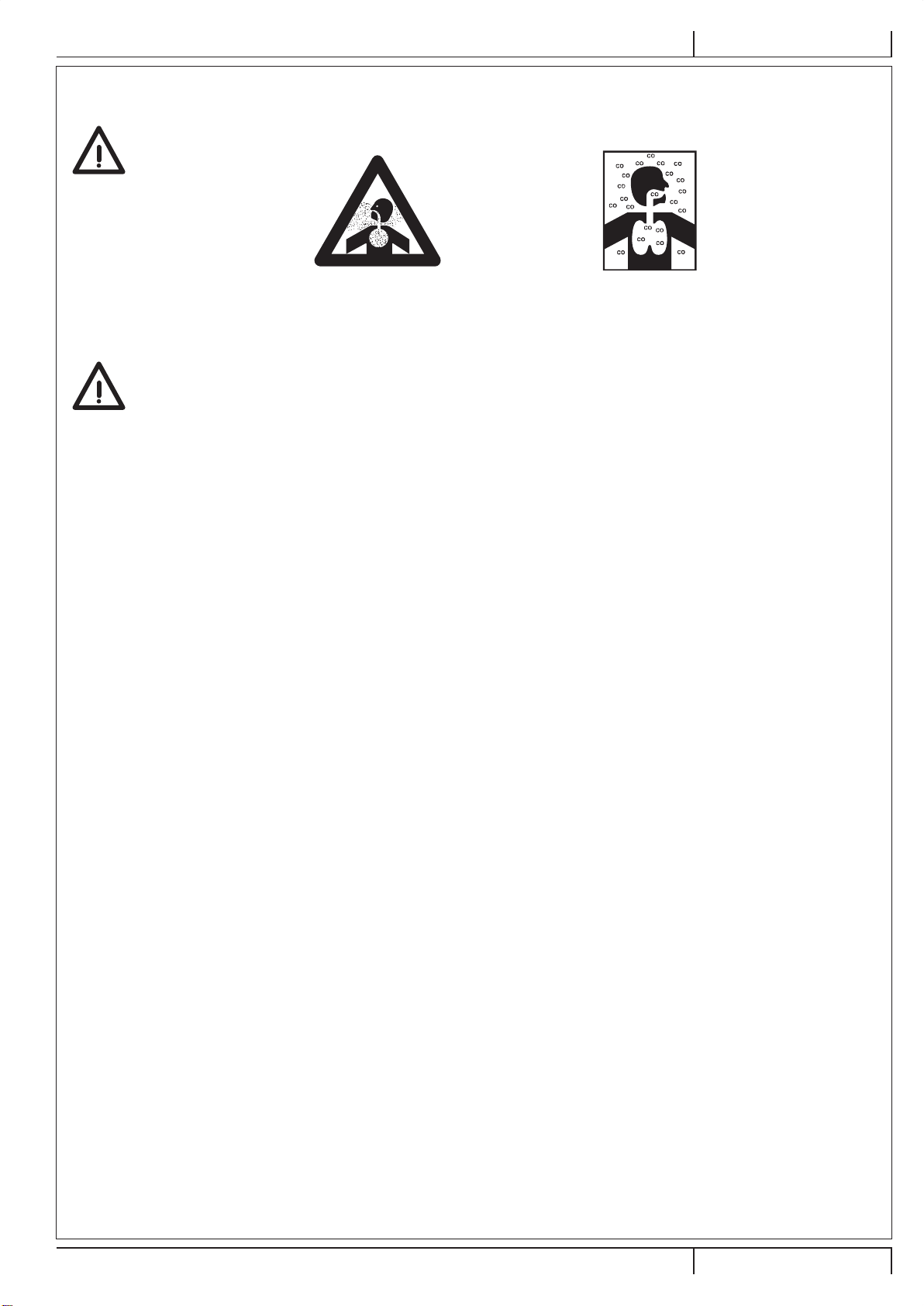
GENERAL INSTRUCTIONS............................................................................................................................................................ 5
HOPPER SAFETY SUPPORT ........................................................................................................................................................ 8
JACKING THE MACHINE................................................................................................................................................................ 8
MACHINE TRANSPORT ................................................................................................................................................................. 8
PUSHING/TOWING THE MACHINE............................................................................................................................................... 8
KNOW YOUR MACHINE ................................................................................................................................................. 9
MACHINE NOMENCLATURE ......................................................................................................................................................... 9
OPERATING CONTROLS..............................................................................................................................................................11
ACCESSORIES/OPTIONS............................................................................................................................................................ 12
TECHNICAL DATA......................................................................................................................................................................... 12
WIRING DIAGRAM........................................................................................................................................................................ 13
HYDRAULIC DIAGRAM ................................................................................................................................................................ 15
PREPARING THE MACHINE FOR USE ....................................................................................................................... 16
PRE-OPERATIONAL CHECKLIST................................................................................................................................................ 16
MAIN BROOM ............................................................................................................................................................................... 16
FUEL.............................................................................................................................................................................................. 16
OPERATING THE MACHINE ........................................................................................................................................ 17
BEFORE STARTING THE MACHINE ........................................................................................................................................... 17
STARTING AND STOPPING THE MACHINE ............................................................................................................................... 17
PARKING BRAKE.......................................................................................................................................................................... 18
SWEEPING ................................................................................................................................................................................... 18
HOPPER DUMPING...................................................................................................................................................................... 19
AFTER USING THE MACHINE..................................................................................................................................................... 20
MACHINE STORAGE.................................................................................................................................................................... 20
FIRST PERIOD OF USE ............................................................................................................................................................... 20
MAINTENANCE............................................................................................................................................................. 20
SCHEDULED MAINTENANCE TABLE ......................................................................................................................................... 21
MAIN BROOM MAINTENANCE .................................................................................................................................................... 22
SIDE BROOM MAINTENANCE..................................................................................................................................................... 24
DUST FILTER MAINTENANCE (PANEL FILTER)......................................................................................................................... 26
SKIRT MAINTENANCE ................................................................................................................................................................. 27
DUSTGUARD SYSTEM WATER FILTER CLEANING (OPTIONAL)............................................................................................. 27
HYDRAULIC OIL ........................................................................................................................................................................... 28
ENGINE OIL .................................................................................................................................................................................. 28
ENGINE AIR FILTER CLEANING.................................................................................................................................................. 29
ENGINE COOLANT....................................................................................................................................................................... 29
FUSE CHECK/REPLACEMENT/RESET....................................................................................................................................... 30
TROUBLESHOOTING................................................................................................................................................... 31
SCRAPPING .................................................................................................................................................................. 32
33019864(3)2012-03.indb 1 16/04/2012 12:40:50

ENGLISH INSTRUCTION FOR USE
2Proterra™ - 33019864
INTRODUCTION
NOTE
The numbers in brackets refer to the components shown in Machine Description chapter.
MANUAL PURPOSE AND CONTENTS
The purpose of this Manual is to provide the operator with all necessary information to use the machine properly, in a safe and
autonomous way. It contains information about technical data, safety, operation, storage, maintenance, spare parts and disposal.
Before performing any procedure on the machine, the operators and qualied technicians must read this Manual carefully. Contact
Advance in case of doubts concerning the interpretation of the instructions and for any further information.
TARGET
This Manual is intended for operators and technicians qualied to perform the machine maintenance.
The operators must not carry out operations reserved for qualied technicians. Advance will not be responsible for damages coming
from failure to follow these instructions.
HOW TO STORE THIS MANUAL
The Instructions for use Manual must be kept near the machine, inside an adequate case, away from liquids and other substances
that can cause damage to it.
IDENTIFICATION DATA
The machine model and serial number are shown on the plate (10) placed on the frame.
Product code and year of production are marked on the same plate.
The machine model and serial number are shown on the plate (31).
This information is useful when ordering machine and engine spare parts. Use the following table to write down the machine and
engine identication data.
MACHINE model ...............................................................................
PRODUCT code ................................................................................
MACHINE serial number ...................................................................
ENGINE model ..................................................................................
ENGINE serial number ......................................................................
OTHER REFERENCE MANUALS
– Engine Manual, supplied with the machine, to be considered an integral part of this Manual.
– The following Manuals are also available:
• Spare Parts List (supplied with the machine)
• Service Manual (that can be consulted at any Advance Dealer)
SPARE PARTS AND MAINTENANCE
All necessary operating, maintenance and repair procedures must be performed by qualied personnel or by Advance Service
Centers. Only original spare parts and accessories must be used.
Call Advance for service or to order spare parts and accessories, specifying the machine model, product code and serial number.
CHANGES AND IMPROVEMENTS
Advance constantly improves its products and reserves the right to make changes and improvements at its discretion without being
obliged to apply such benets to the machines that were previously sold.
Any change and/or addition of accessory must be approved and performed by Advance.
33019864(3)2012-03.indb 2 16/04/2012 12:40:50

INSTRUCTION FOR USE ENGLISH
33019864 - Proterra™ 3
OPERATION CAPABILITIES
This sweeper has been approved to clean/sweep compact and solid oors, in civil and industrial environments, under safe
operation conditions by a qualied operator.
CONVENTIONS
Forward, backward, front, rear, left or right are intended with reference to the operator’s position, while on the driver’s seat (32).
UNPACKING/DELIVERY
Upon delivery, carefully check that the packing and the machine are not damaged. In case of visible damages, keep the packing
and have it checked by the carrier that delivered it. Call the carrier immediately to ll in a damage claim.
– Check that the machine is equipped as follows:
• Sweeper Instructions for use Manual
• Engine Manual
• Sweeper Spare Parts List
– After removing the packing, remove the wooden blocks next to the wheels.
– Check the engine oil and coolant levels.
– Check the hydraulic oil level.
– Read the instructions in the Preparing the Machine For Use section of this manual, then ll the fuel tank.
– Place a ramp next to the front end of the pallet.
– Read the instructions in the Operating Controls and Operating the Machine sections of this manual and start the engine.
Slowly drive the machine forward down the ramp to the oor.
WARNING!
Use extreme caution when operating the sweeper.
Be certain to be thoroughly familiar with all of the operating instructions prior to using this sweeper.
In case of questions, contact a supervisor or local Advance Industrial Dealer.
Should the sweeper malfunction, do not attempt to correct the problem unless the supervisor directs you to do
so. Have a qualied company mechanic or an authorised Advance Dealer service person make any necessary
corrections to the equipment.
Use extreme care when working on this machine. Neckties, loose clothing, long hair, rings and bracelets can get
caught in moving parts.
Before working on the machine turn the ignition key (65) to “0”, remove the key, engage the parking and
disconnect the battery.
Use good common sense, practice good safety habits and pay attention to the yellow decals on this machine.
Drive the machine slowly on inclines. Use the brake pedal (35) to control machine speed while descending
inclines.
Do not turn the machine on an incline; drive straight up or down.
The maximum rated incline during transport with a 3 cylinder model is 17%.
SAFETY
The following symbols indicate potentially dangerous situations. Always read this information carefully and take all necessary
precautions to safeguard people and property.
The operator’s cooperation is essential in order to prevent injury. No accident prevention program is effective without the total
cooperation of the person responsible for the machine operation. Most of the accidents that may occur while working or moving
around are caused by failure to comply with the simplest rules for exercising prudence. A careful and prudent operator is the best
guarantee against accidents and is essential for successful completion of any prevention program.
33019864(3)2012-03.indb 3 16/04/2012 12:40:50

ENGLISH INSTRUCTION FOR USE
4Proterra™ - 33019864
VISIBLE SYMBOLS ON THE MACHINE
WARNING!
Carefully read all the instructions
before performing any operation on the
machine.
DANGER!
Internal combustion engine.
Do not inhale exhaust gas fumes.
Carbon monoxide (CO) can cause brain
damage or death.
WARNING!
Do not wash the machine with
pressurized water.
X % WARNING!
Do not use the machine on slopes with
a gradient exceeding the specications.
WARNING!
Hot parts, danger of burns.
WARNING!
Moving parts.
WARNING!
Moving parts, danger of crushing.
WARNING!
Parts under voltage.
Presence of corrosive uids.
Jacking locations.
Hydraulic lifting system and/or safety
stands anchoring locations.
Greasing point.
SYMBOLS THAT APPEAR ON THIS MANUAL
DANGER!
It indicates a dangerous situation with risk of death for the operator.
WARNING!
It indicates a potential risk of injury for people or damage to objects.
CAUTION!
It indicates a caution or a remark related to important or useful functions. Pay careful attention to the
paragraphs marked by this symbol.
NOTE
It indicates a remark related to important or useful functions.
CONSULTATION
It indicates that it is necessary to consult the Instructions for use Manual before performing any procedure.
33019864(3)2012-03.indb 4 16/04/2012 12:40:51

INSTRUCTION FOR USE ENGLISH
33019864 - Proterra™ 5
GENERAL INSTRUCTIONS
Specic warnings and cautions to inform about potential damages to people and machine are shown below.
DANGER!
–Carbon monoxide (CO) can cause brain damage or death.
–The internal combustion engine of this machine can emit carbon monoxide.
–Do not inhale exhaust gas fumes.
–Only use indoors when adequate ventilation is provided, and with the help of an assistant.
DANGER!
–Before performing any maintenance, repair, cleaning or replacement procedure disconnect the battery
connector, remove the ignition key and engage the parking brake.
–This machine must be used by properly trained operators only.
–Sharp turns must be made at slowest possible speed. Avoid: abrupt turns on incline, turns when the hopper
is lifted.
–Do not lift the hopper when the machine is on incline. The machine loses stability on incline or when the
hopper is full. Regularly check the tire pressure.
–Do not wear jewels when working near electrical components.
–Keep the battery away from sparks, ames and incandescent material. During the normal operation explosive
gases are released.
–Do not work under the lifted machine without supporting it with safety stands.
–When working under the open hood, ensure that it cannot be closed by accident.
–Do not operate the machine near toxic, dangerous, ammable and/or explosive powders, liquids or vapors:
This machine is not suitable for collecting dangerous powders.
–Be careful, fuel is highly ammable.
–Do not smoke or bring naked ames in the area where the machine is refuelled or where the fuel is stored.
–Refuel outdoors or in a well-ventilated area, with the engine off.
–Avoid contact with skin and do not breathe in fuel vapors. Keep out of reach of children.
–Do not lay any object on the engine.
–Stop the engine before performing any procedure on it. To prevent the engine from starting accidentally,
disconnect the battery negative terminal.
–See also the SAFETY RULES in the Engine Manual, which is to be considered an integral part of this Manual.
–Lead batteries (WET) are installed on this machine, do not tilt the machine more than 30° from its horizontal
position to prevent the highly corrosive acid to leak out of the batteries. When the machine is to be tilted to
perform maintenance procedures, remove the batteries.
–Do not use the machine in case of gas leaks. Disconnect the fuel hose and replace the LPG tank. If the gas
leak persists, disconnect the fuel hose and contact the Advance Service Center.
33019864(3)2012-03.indb 5 16/04/2012 12:40:51

ENGLISH INSTRUCTION FOR USE
6Proterra™ - 33019864
WARNING!
–Carefully read all the instructions before performing any maintenance/repair procedure.
–When working near the hydraulic system, always wear protective clothes and safety glasses.
–Pay attention to hot parts when working near the engine, the mufer, the manifold and the cooler.
–Use only as shown in this Manual. Use only Nilsk’s recommended accessories.
–This machine is not intended for use by persons (including children) with reduced physical, sensory or
mental capabilities, or lack of experience and knowledge, unless they have been given supervision or
instruction concerning use of the machine by a person responsible for they safety. Children should be
supervised to ensure that they do not play with the machine.
–Close attention is necessary when used near children.
–Take all necessary precautions to prevent hair, jewels and loose clothes from being caught by the machine
moving parts.
–Wear proper ear protection when using the machine.
–To avoid any unauthorized use of the machine, remove the ignition key.
–Do not leave the machine unattended without being sure that it cannot move independently.
–Do not use the machine on slopes with a gradient exceeding the specications.
–Do not tilt the machine more than the angle indicated on the machine itself, in order to prevent instability.
–Use only brooms supplied with the machine or those specied in the Instructions for use Manual. Using
other brooms could reduce safety.
–Before using the machine, close all doors and/or covers, as indicated in the Instructions for use Manual.
–Use the machine only where a proper lighting is provided.
–Working lights (optional) have to be used only to enhance visibility on the oor to be cleaned, but they do not
authorize anyone to use the sweeper in dark environments.
–If the machine is to be used where there are other people besides the operator, it is necessary to install the
pivoting light and the reverse gear buzzer (optional).
–Do not wash the machine with direct or pressurised water jets, or with corrosive substances.
–Do not use compressed air to clean this type of machine, except for the lters (see the relevant paragraph).
–While using this machine, take care not to cause damage to people and property.
–Do not lean liquid containers on the machine, use the relevant can holder.
–The machine storage temperature must be 32 °F and 104 °F (0 °C to +40 °C).
–The machine working temperature must be 32 °F and 104 °F (0 °C to +40 °C).
–The humidity must be between 30% and 95%.
–Always protect the machine against the sun, rain and bad weather, both under operation and inactivity
condition. Store the machine indoors, in a dry place. This machine must be used in dry conditions, it must
not be used or kept outdoors in wet conditions.
–Do not use the machine as a means of transport, or for pushing/towing.
–Do not allow the brooms to operate while the machine is stationary to avoid damaging the oor.
–In case of re, use a powder re extinguisher, not a water one.
–Do not bump into shelves or scaffoldings, particularly where there is a risk of falling objects.
–Adjust the operation speed to suit the oor conditions.
–Avoid sudden stops when the machine is going downhill. Avoid sharp turns. Drive at slow speed when going
downhill.
–This machine cannot be used on roads or public streets.
–Do not tamper with the machine safety guards.
–Follow the routine maintenance procedures scrupulously.
–Do not allow any object to enter into the openings. Do not use the machine if the openings are clogged.
Always keep the openings free from dust, hairs and any other foreign material which could reduce the air
ow.
33019864(3)2012-03.indb 6 16/04/2012 12:40:51

INSTRUCTION FOR USE ENGLISH
33019864 - Proterra™ 7
WARNING!
–(Only for versions equipped with dust guard system) Pay attention during machine transport when
temperature is below freezing point. The water in the system tank or hoses could freeze and seriously
damage the machine.
–Do not remove or modify the plates afxed to the machine.
–In case of machine malfunctions, ensure that these are not due to lack of maintenance. Otherwise, request
assistance from the authorised personnel or from an authorised Service Center.
–In case of part replacement, order ORIGINAL spare parts from an authorised Dealer or Retailer.
–To ensure the proper and safe operation of the machine, have the scheduled maintenance, detailed in the
relevant chapter of this Manual, performed by the authorised personnel or an authorised Service Center.
–The machine must be disposed of properly, because of the presence of toxic-harmful materials (batteries,
oil, plastics, etc.), which are subject to standards that require disposal in special centres (see Scrapping
chapter).
–While the engine is running the silencer heats up. Do not touch the silencer to avoid serious scalding or re.
–Running the engine with an insufcient quantity of oil can seriously damage the engine. Check the oil level
with the engine off and the machine on a level surface.
–Never run the engine if the air lter is not installed, because the engine could be damaged.
–All engine servicing procedures should be performed by an authorised Dealer.
Only use original spare parts or parts of matching quality for the engine. Using spare parts of lower quality
can seriously damage the engine.
–See also the SAFETY RULES in the Engine Manual, which is to be considered an integral part of this Manual.
Guide lines to bacteria control and other dangers coming from the presence of microbes in the dust guard system
(optional).
WARNING!
To prevent the operators and other people from developing infections caused by microbes and Legionella that
may ourish in the dust guard system, take the following precautions:
–If possible, ll the tank with cold water (< 20 °C).
–DO NOT use stagnant water to ll the tank.
–DO NOT use recycled water, undrinkable water or water that has been in contact with the soil.
–Adjust and turn the nozzles towards the oor only, from preventing possible inhaling.
–Do not store the machine outdoors or near sources of heat.
–Do not over-ll the tank. Fill the tank sufciently so that it can be emptied by using the system.
–Empty the tank every 10 hours or once a week, according to the use.
–If the machine is not used for more than one week, empty the tank completely, and let it dry before storing it.
–If the tank cannot be cleaned regularly, consider using a biocide that can kill or exert a controlling effect on
Legionella bacteria. Biocide must be chosen according to the local regulations and must be used according
to the relevant instructions and cautions, to avoid that the personnel gets affected by dangerous chemical
substances.
–If chemical products have to be used in the water tank, it is mandatory to apply the relevant information and
caution labels of the product.
33019864(3)2012-03.indb 7 16/04/2012 12:40:51

ENGLISH INSTRUCTION FOR USE
8Proterra™ - 33019864
HOPPER SAFETY SUPPORT
CAUTION!
Before performing any maintenance procedure under or near to the lifted hopper, pull the locking handle (39) to
make sure the hopper safety support (5) is in place. The hopper safety support (5) holds the hopper in the lifted
position to allow work to be performed under the hopper. Never rely on the machine’s hydraulic components to
safely support the hopper.
JACKING THE MACHINE
WARNING!
Never work under a machine without safety stands or blocks to support the machine.
When jacking the machine, do so at designated locations (do not jack on the hopper) - see jacking locations (8).
MACHINE TRANSPORT
WARNING!
Before transporting the machine on an open truck or trailer, make sure that:
–All access doors are latched securely.
–The machine is tied down securely.
–The parking brake is engaged.
PUSHING/TOWING THE MACHINE
CAUTION!
The hydraulic pump can be damaged if the machine is towed when the screw is in the normal working position
(locked).
The machine hydraulic pump (45) is equipped with a screw that disengages the traction system. The system prevents damage to
the hydraulic system when the machine is being towed/pushed short distances without using the engine.
1. To access the unlocking screw, open the engine compartment hood (1) by using the unlocking push-button (25) and locate the
hydraulic pump (45) in the front part of the engine (44).
2. Remove the supplied wrench (A, Fig. 1) on the pump lever.
3. With the wrench, turn the socket head screw (B) 1/4 of a turn counter-clockwise (C) to disengage the hydrostatic lock between
the engine and pump.
4. Tow or push the machine no faster than a normal walking pace (3-4.5 km/h) and for short distances only.
NOTE
If the machine is to be moved long distances the driving wheels need to be raised off the oor and placed on a suitable
transport dolly.
5. After pushing/towing the machine, turn the socket head screw 1/4 of a turn clockwise (D) to reset the hydrostatic lock and
hydraulic functions.
NOTE
If the screw is left in unlocking position (C), the hydraulic pump cannot drive the machine.
C
D
A
A
B
P100320
Figure 1
33019864(3)2012-03.indb 8 16/04/2012 12:40:52

INSTRUCTION FOR USE ENGLISH
33019864 - Proterra™ 9
KNOW YOUR MACHINE
MACHINE NOMENCLATURE
1. Engine compartment hood
2. Left side main broom access panel
3. Battery
4. Left side hood
DustGuard system tank (optional)
5. Hopper safety support
6. Hopper hood latch
7. Working light (optional)
8. Jacking locations (rear location is under the engine
radiator)
9. Right side broom
10. Serial number plate/technical data/conformity certication
11. Dust lter shaker assembly
12. Hopper dust control lter
Panel lter (standard)
Closed pocket lter (optional)
13. Filter shaker assembly mounting knobs
14. Hydraulic oil lter
15. Left side broom (optional)
16. Hopper hood
17. Hopper hood support rod
18. Right side main broom access panel
19. Hydraulic oil tank
20. Hydraulic oil tank plug
21. LPG fuel tank
22. LPG tank safety valve
23. Radiator plug
24. Engine air lter
25. Engine compartment hood unlocking push-button
26. Tie-down locations (3)
27. Air lter service indicator
28. DustGuard system nozzles (optional)
29. DustGuard system tank plug (optional)
30. Water lter (optional)
31. Engine model and serial number plate
1
2
45
31
4
32
19
30
8
5
15
9
6
7
11
12
13
14
20
17
28
47 43
26
P100317
33019864(3)2012-03.indb 9 16/04/2012 12:40:55

ENGLISH INSTRUCTION FOR USE
10 Proterra™ - 33019864
MACHINE NOMENCLATURE (Continues)
32. Driver’s seat
33. Control panel (see the following paragraph)
34. Steering wheel
35. Brake pedal
36. Parking brake pedal
(To engage/disengage the parking brake, use
simultaneously with the brake pedal)
37. Forward/reverse gear pedal
38. Circuit breaker panel (see the Fuse Check/Replacement/
Reset paragraph)
39. Hopper safety support handle
• Pull backward to lock the support
• Push forward to unlock the support
40. Driver’s seat adjustment lever
41. Engine air grid
42. Rear driving and steering wheel
43. Front wheels
44. Engine
45. Hydraulic pump
46. Engine coolant/hydraulic oil radiator
47. Hopper
48. Fuses (see the Fuse Check/Replacement/Reset
paragraph)
49. Fire extinguisher (optional)
3
23
24
27
25
29
26
26
8
22
21 18
40
41
43
44
45
46
49
42
33 34
36
37
48
38
39
35
16
10
P100318A
33019864(3)2012-03.indb 10 16/04/2012 12:40:58

INSTRUCTION FOR USE ENGLISH
33019864 - Proterra™ 11
OPERATING CONTROLS
51. Engine speed lever
• (Forward) working speed
• (Backward) idle speed
52. Side broom lever
• (Forward) side broom lowered
• (Backward) side broom lifted
53. Main broom lever
• (Forward) main broom lowered
• (Backward) main broom lifted
54. Hopper lever
• (Forward) hopper lowered
• (Backward) hopper lifted
55. Hopper dumping door lever
• (Forward) dumping door opened
• (Backward) dumping door closed
56. Hour counter
57. Fuel level indicator
58. Fuel level warning light
59. Hopper overtemperature warning light
60. Clogged hopper lter warning light
61. Low oil pressure warning light
62. Battery charger warning light
63. Engine coolant overtemperature warning light
64. Parking brake warning light
65. Ignition key:
• When turned to “0” it stops the engine and disables all
machine functions.
• When turned to “I” it enables the machines functions.
• When turned to “II” it starts the engine.
As soon as the engine starts release the key, which will
return to “I”.
66. Horn switch
67. Vacuum fan/Shaker switch
• (Lower position) lter shaker activation
• (Upper position) vacuum fan and dust control system
activation
68. DustGuard system switch (optional)
69. Engine choke lever
70. Working light switch (optional)
71. Hazard warning light switch (optional)
72. Turn signal switch (optional)
73. Steering wheel adjustment lever (optional)
61
51525355 54
5
5
5
5
62 63 64 65 66 67 6968
70
71
72
73
6
7
8
9
60
P100319A
33019864(3)2012-03.indb 11 16/04/2012 12:40:58

ENGLISH INSTRUCTION FOR USE
12 Proterra™ - 33019864
ACCESSORIES/OPTIONS
In addition to the standard components, the machine can be equipped with the following accessories/options, according to the
machine specic use:
– Main and side brooms with harder or softer bristles
– Polyester Water Resistant dust lter
– Clogged lter sensor
– DustGuard system
– Fire extinguisher
– Headlights
– Working light
– Flashing light
– Non-marking wheels
– Tilt steering wheel
– Driver’s seat with suspensions
– Safety belts
– Side broom guard
– Overhead Guard
– Overhead guard canopy
– Soft cabin
– Rearview mirrors
– Rear bumper
– Reverse gear buzzer
– Hopper protection
– Anti-skid mat
– Hopper lower protection
– Driver’s seat plate
– Driver’s seat armrests
– Polyester closed pocket lter
For further information about the above-mentioned accessories, contact an authorised Retailer.
TECHNICAL DATA
Dimensions and weights Proterra™ LPG Proterra™ LPG BR
Cleaning path with main broom 35.5 in (900 mm)
Cleaning path with one side broom 49.25 in (1,250 mm)
Cleaning path with two side brooms (optional) 63 in (1,600 mm)
Machine length 87.5 in (2,220 mm)
Machine width (broom hubs) 52 in (1,320 mm)
Maximum machine height 57.5 in (1,460 mm)
Maximum machine height with Overhead Guard (optional) 79 in (2,000 mm)
Minimum distance from the oor (skirts not included) 4.25 in (110 mm)
Maximum hopper lifting height 62.5 in (1,590 mm)
Main broom size (diameter x length) 12.2 x 35.5 in (310 x 900 mm)
Side broom diameter 21.5 in (550 mm)
Tire pressure 85 psi (6 Bar)
Maximum capacity 800 lb (365 kg)
IP protection class X3
Front axle curb weight 1,180 lb (535 kg)
Rear axle curb weight 905 lb (410 kg)
Total machine curb weight (without operator) 2,085 lb (945 kg)
Maximum weight (GVW) 2,910 lb (1,320 kg)
Machine weight for shipment 2,315 lb (1,050 kg)
Refuelling data Proterra™ LPG Proterra™ LPG BR
Hydraulic system oil tank capacity 30.6 qt (29 liters)
Engine oil pan capacity (*) 3.59 qt (3.4 liters)
Engine oil type (**) SAE 10W-30
Engine coolant quantity (**) 4.2 qt (4 liters)
(*) For other engine data/values, see the Engine Manual.
(**) For engine oil and coolant data, and for technical specications refer to the Engine Manual.
33019864(3)2012-03.indb 12 16/04/2012 12:40:59

INSTRUCTION FOR USE ENGLISH
33019864 - Proterra™ 13
Performance data Proterra™ LPG Proterra™ LPG BR
Maximum forward speed (for transport only) 7.5 mph (12 km/h)
Gradeability when working 17% (9.6°)
Minimum turning radius 60.2 in (1,530 mm)
Sound pressure level at workstation (ISO 11201, ISO 4871, EN 60335-2-72) (LpA) 87 ± 3 dB(A) 89 ± 3 dB(A)
Machine output acoustic power (ISO 3744, ISO 4871, EN 60335-2-72) (LwA) 107 dB(A) 109 dB(A)
Vibration level at the operator’s arms (ISO 5349-1, EN 60335-2-72) < 2.5 m/s2
Vibration level at the operator’s body (ISO 2631-1, EN 60335-2-72) < 0.5 m/s2
Hopper capacity Theoretic: 11.25 cu·ft (315 liters)
Real: 8.00 cu·ft (226 liters)
Hopper maximum lift capacity 800 lb (363 kg)
DustGuard system tank capacity (optional) 11.9 gal (45 liters)
WIRING DIAGRAM
Key
ALT Alternator
BAT Battery
BE1 Pivoting light (optional)
BZ1 Reverse gear buzzer (optional)
ES1 Vacuum system relay
ES2 Filter shaker relay
ES3 LPG safety relay
EV2 LPG solenoid valve
EV3 LPG safety solenoid valve
F1 Vacuum system circuit breaker (30 A)
F2 Filter shaker circuit breaker (16 A)
F3 Water pump circuit breaker (10 A) (optional)
F4 Ignition key circuit breaker (30 A)
F5 Engine accessory circuit breaker (16 A)
F6 Working light fuse (10 A) (optional)
F8 Cab blower resettable fuse (optional)
F10 Alternator fuse box and fuse (50 A)
F11 Hood inner light fuse (1 A) (optional)
HN Horn
IGN Ignition unit
K1 Ignition switch
L1-L2 Front working light (optional)
L3 Driver’s side working light (optional)
L4 Rear working light (optional)
L5 Engine hood inner light (optional)
M1 Vacuum system motor
M2 Filter shaker motor
M3 Water pump motor (optional)
M4 Cab blower motor (optional)
M7 Windscreen wiper motor (optional)
MST Starter
SE1 Oil pressure sensor
SE2 Water temperature sensor
SE3 Clogged hopper lter sensor (optional)
SE6 Hopper temperature sensor (optional)
SE7 Engine speed sensor
SE8 Low fuel sensor
SPK Glow plug coils
STR Gauge
SW1 Vacuum system/lter shaker switch
SW2 Horn switch
SW3 Driver’s seat microswitch
SW4 Reverse gear proximity sensor (optional)
SW5 Cab blower switch (optional)
SW6 Water pump switch (optional)
SW7 Working light switch (optional)
SW13 Driver’s side working light switch (optional)
SW14 Rear working light switch (optional)
SW15 Hood inner light switch (optional)
SW16 Windscreen wiper switch (optional)
SW17 Lifted hood microswitch (optional)
T1 Filter shaker timer
T2 Filter shaker timer 2
T3 Driver’s seat timer
T4 LPG safety timer
Color code
BK Black
BU Light blue
BN Brown
GN Green
GY Grey
OG Orange
PK Pink
RD Red
VT Violet
WH White
YE Yellow
33019864(3)2012-03.indb 13 16/04/2012 12:40:59

ENGLISH INSTRUCTION FOR USE
14 Proterra™ - 33019864
WIRING DIAGRAM PROTERRA™ LPG
A
B
C
D
E
A
B
C
D
E
P100330LPG
33019864(3)2012-03.indb 14 16/04/2012 12:40:59

INSTRUCTION FOR USE ENGLISH
33019864 - Proterra™ 15
HYDRAULIC DIAGRAM
Key
1. Oil tank
2. Oil lter
3. Drive system pump
4. Accessory pump
5. Drive system motor
6. Power steering
7. Steering cylinder
8. Priority valve
9. Manifold 3 levers
10. Hopper lifting cylinder
11. Skirt cylinder
12. Main broom motor
13. Main broom cylinder
14. Manifold 1 lever
15. Right side broom motor
16. Right side broom cylinder
17. Check valve
18. One-way valve
19. Double check valve
20. Manifold block
21. Left side broom motor (optional)
22. Left side broom cylinder (optional)
23. Oil cooler
20 9
11 10
13
12
14
15
21
16
17
18
19
22
1
2
23
3
456
7
8
2
P100328
33019864(3)2012-03.indb 15 16/04/2012 12:40:59

ENGLISH INSTRUCTION FOR USE
16 Proterra™ - 33019864
PREPARING THE MACHINE FOR USE
WARNING!
On some points of the machine there are adhesive plates indicating:
–DANGER
–WARNING
–CAUTION
–CONSULTATION
While reading this Manual, the operator must pay particular attention to the symbols shown on the plates (see the Visible Symbols
On The Machine paragraph).
Do not cover these plates for any reason and immediately replace them if they are damaged.
PRE-OPERATIONAL CHECKLIST
Before Each Use:
– Inspect the machine for damage, oil or coolant leaks.
– Check the engine coolant level (23) (see the relevant paragraph).
– Check the engine oil level (44) (see the relevant paragraph).
– Check the hydraulic oil level (19) (see the relevant paragraph).
– Check the fuel level indicator (57), if the warning light (58) is on replace the LPG tank (21).
– Check that the pressure of all three tires is 85 psi (6 Bar).
– Check the air lter service indicator (see the relevant paragraph).
In the driver’s seat:
– Be sure to understand the operating controls and their functions.
– Adjust the seat with the lever (40) to allow easy reach of all controls.
– Insert the ignition key (65) and turn it to “I”:
• Check the horn (66), hour counter (56) and headlights (70, optional) for proper operation.
• Turn the ignition key (65) to “0”.
– Check the Parking Brake (35 and 36). The brake must hold its (locked parked) setting rmly without easily being released.
(Report all defects immediately to service personnel).
Plan cleaning in advance:
– Arrange long runs with a minimum of stopping or starting.
– Allow a small amount of broom path overlap to ensure complete coverage.
– Avoid making sharp turns, bumping into posts, or scraping the side of the machine.
MAIN BROOM
Several different main brooms are available for this machine. To select the best broom for the surface and litter to be swept, contact
a Advance Retailer.
NOTE
To install the main broom, refer to Main Broom Maintenance paragraph.
FUEL
CAUTION!
–Always stop the engine before lling the fuel tank.
–Do not smoke while lling the fuel tank.
–Fill the fuel tank in a well-ventilated area.
–Do not ll the fuel tank near sparks or open ame.
DANGER!
–Carbon monoxide (CO) can cause brain damage or death.
–The internal combustion engine of this machine can emit carbon monoxide.
–Do not inhale exhaust gas fumes.
–Only use indoors when adequate ventilation is provided, and with the help of an assistant.
33019864(3)2012-03.indb 16 16/04/2012 12:41:00

INSTRUCTION FOR USE ENGLISH
33019864 - Proterra™ 17
DANGER!
Before replacing the tank, close the safety valve and disconnect the hose.
1. Assembly only a LPG container with the following specications:
• DOT fuel container marked for a minimum service pressure of 240 psi (1.7 MPa). It shall bear marking DOT-4BA240
or DOT-4BW240.
2. Connect the fuel hose and open the cutoff valve on the tank. Always wear gloves when connecting and disconnecting the fuel
hose.
3. When the machine is operating, close the LPG tank valve.
NOTE
Place the LPG tank in a proper horizontal position. Connect the fuel hose to the tank and check that there are no gas
leaks.
WARNING!
Do not use the machine in case of gas leaks. Disconnect the fuel hose and replace the LPG tank. If the gas leak
persists, disconnect the fuel hose and contact the Advance Service Center.
OPERATING THE MACHINE
The Proterra™ is a rider-type automatic oor sweeping machine. The controls were designed to be user friendly. For single pass
sweeping the operator can simply lower the main broom.
BEFORE STARTING THE MACHINE
1. Be sure to understand the operating controls and their functions.
2. Plan the cleaning route. Arrange long, straight passes with as few turns as possible.
3. Check the brake pedal (35). The pedal should be rm.
WARNING!
If the pedal is “spongy” or fades under pressure, do not drive the machine.
Report all defects immediately to service personnel.
Filling the dust guard system water tank (optional)
1. Remove the plug (29) to reach the ller neck.
2. Fill the tank (4) with clean water. Do not ll the tank completely, leave a few centimeters from the edge.
STARTING AND STOPPING THE MACHINE
Starting the machine
NOTA
The driver’s seat (32) is equipped with a safety sensor, which allows the machine to be started up and driven only when
the operator is on the driver’s seat.
1. Slowly open the safety valve on the LPG tank (21). Pull the engine choke lever (67).
2. Turn the ignition key (65) clockwise to position “II”, then release it when the engine starts.
If the engine does not start after running the starter for 15 seconds, release the ignition key, wait 1 minute and then repeat
steps 1 and 2.
After the ignition, let the engine run for a few seconds, then release the choke lever (67).
3. Before using the machine, run the engine at idle for 5 minutes by turning the engine speed lever (51) backward (idle speed).
4. Disengage the parking brake.
5. Turn the engine speed lever (51) forward (working speed) and drive the machine at slow speed for 2 or 3 minutes to warm up
the hydraulic system.
6. Press the front part of the drive pedal (37) to move forward and the rear part to move backward.
The drive speed can be adjusted from zero to maximum speed by increasing the pressure on the pedal.
WARNING!
When steering, avoid abrupt direction changes, pay careful attention and drive the machine at slow speed,
especially when the hopper is full or when operating on inclines.
Drive the machine slowly on inclines. Use the brake pedal (35) to control machine speed while descending
inclines.
Do not turn the machine on an incline; drive straight up or down.
Stopping the machine
7. To stop the machine release the pedal (37).
To stop the machine quickly, press also the brake pedal (36).
8. Turn off the machine by turning the ignition key (65) to “0”, then remove it.
9. Engage the parking brake.
33019864(3)2012-03.indb 17 16/04/2012 12:41:00
This manual suits for next models
1
Table of contents
Languages:
Other Advance acoustic Blower manuals
Popular Blower manuals by other brands

Cincinnati Fan
Cincinnati Fan CPF Installation, safety, operation & maintenance manual amd parts list

DeWalt
DeWalt DWH205 manual

Makita
Makita DAS180 instruction manual

EDM Product
EDM Product 08767 instruction manual

DeWalt
DeWalt DCMBA572X1 Original instructions

Sweepster
Sweepster WSP36 series Operator and parts manual