Advance acoustic Terra 28B User manual

TerraTM 28B
SERVICE MANUAL
Advance model: 908 4702 010
1463163000(1)2007-02

ENGLISH SERVICE MANUAL
21463163000(1)2007-02 TerraTM 28B

SERVICE MANUAL ENGLISH
TerraTM 28B 1463163000(1)2007-02 1
GENERAL INFORMATION ........................................................................................................................................ 2
CONVENTIONS .................................................................................................................................................... 2
MACHINE LIFTING ............................................................................................................................................... 2
MACHINE TRANSPORT ....................................................................................................................................... 2
OTHER AVAILABLE MANUALS ............................................................................................................................ 2
SAFETY ................................................................................................................................................................ 3
GENERAL INSTRUCTIONS ................................................................................................................................. 3
TECHNICAL DATA ................................................................................................................................................ 4
MAINTENANCE .................................................................................................................................................... 5
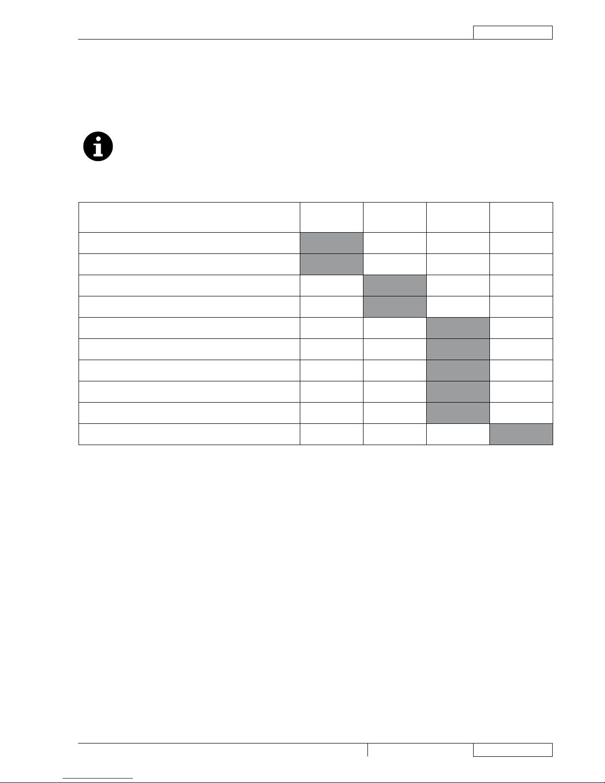
SCHEDULED MAINTENANCE TABLE ................................................................................................................. 5
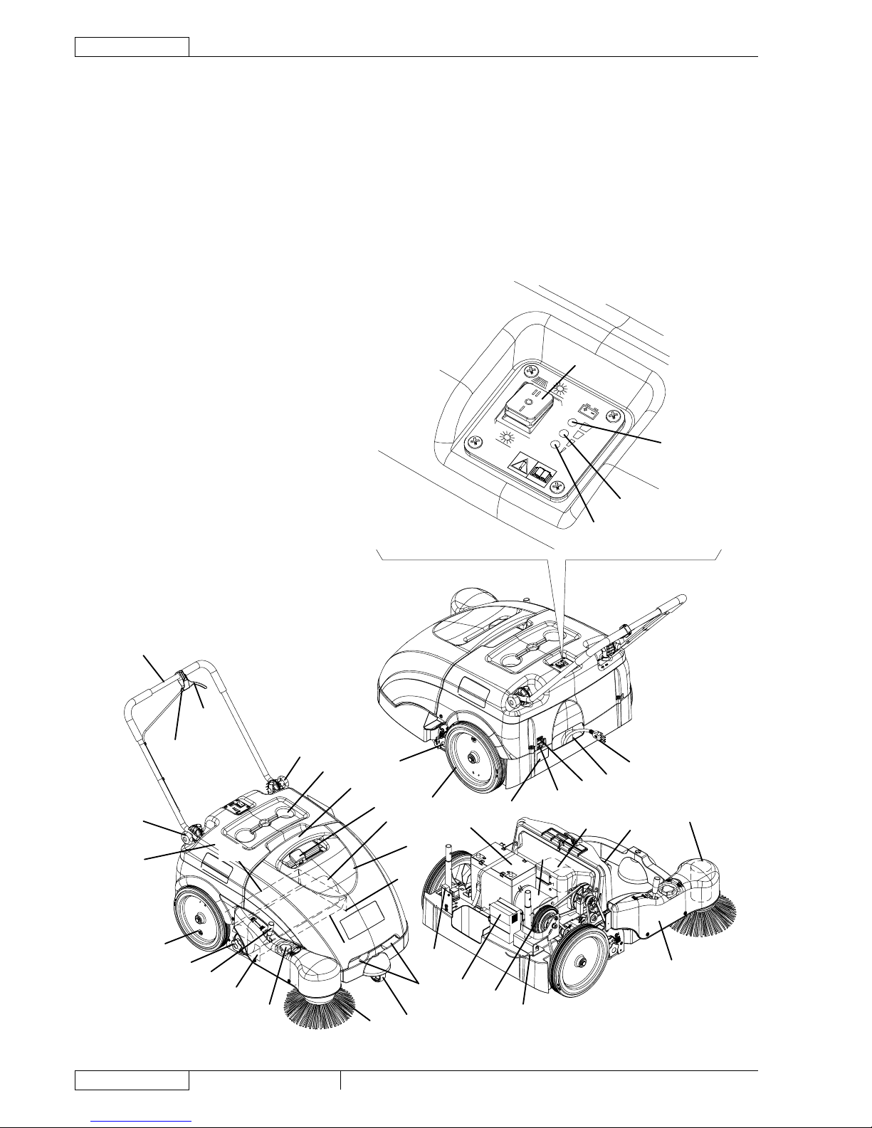
MACHINE NOMENCLATURE ............................................................................................................................... 6
SWEEPING SYSTEM ................................................................................................................................................ 7
SIDE BROOM HEIGHT CHECK AND ADJUSTMENT .......................................................................................... 7
SIDE BROOM DISASSEMBLY/ASSEMBLY ......................................................................................................... 8
MAIN BROOM HEIGHT CHECK AND ADJUSTMENT ......................................................................................... 9
MAIN BROOM DISASSEMBLY/ASSEMBLY ....................................................................................................... 10
MAIN MOTOR-TO-IDLER GEAR BELT DISASSEMBLY/ASSEMBLY (FOR MAIN BROOM) ............................. 11
MAIN BROOM BELT DISASSEMBLY/ASSEMBLY ............................................................................................. 12
SIDE BROOM MOTOR ELECTRICAL INPUT CHECK ....................................................................................... 13
SIDE BROOM MOTOR DISASSEMBLY/ASSEMBLY ......................................................................................... 14
TROUBLESHOOTING ........................................................................................................................................ 15
SKIRT ....................................................................................................................................................................... 16
SKIRT HEIGHT AND OPERATION CHECK ........................................................................................................ 16
LEFT SIDE SKIRT DISASSEMBLY/ASSEMBLY ................................................................................................. 17
RIGHT SIDE SKIRT DISASSEMBLY/ASSEMBLY .............................................................................................. 18
REAR SKIRT DISASSEMBLY/ASSEMBLY ......................................................................................................... 19
FRONT SKIRT DISASSEMBLY/ASSEMBLY ...................................................................................................... 19
DUST AND DEBRIS COLLECTION SYSTEM ........................................................................................................ 20
DUST FILTER CLEANING AND INTEGRITY CHECK, HOPPER GASKET CHECK .......................................... 20
FILTER SHAKER OPERATION CHECK ............................................................................................................. 21
VACUUM SYSTEM MOTOR ELECTRICAL INPUT CHECK ............................................................................... 22
VACUUM SYSTEM MOTOR DISASSEMBLY/ASSEMBLY ................................................................................. 23
TROUBLESHOOTING ........................................................................................................................................ 23
DRIVE SYSTEM ....................................................................................................................................................... 24
DRIVE SYSTEM CONTROL CABLE ADJUSTMENT ......................................................................................... 24
DRIVING BELT DISASSEMBLY/ASSEMBLY ...................................................................................................... 25
TROUBLESHOOTING ........................................................................................................................................ 26
MAIN MOTOR .......................................................................................................................................................... 27
DRIVING BELT AND CLUTCH VISUAL INSPECTION AND ADJUSTMENT ...................................................... 27
MAIN MOTOR ELECTRICAL INPUT CHECK ..................................................................................................... 28
MAIN MOTOR CARBON BRUSH CHECK AND REPLACEMENT ..................................................................... 29
MAIN MOTOR DISASSEMBLY/ASSEMBLY ....................................................................................................... 30
TROUBLESHOOTING ........................................................................................................................................ 32
OTHER SYSTEMS ................................................................................................................................................... 33
NUT AND SCREW TIGHTENING CHECK .......................................................................................................... 33
HOOD DISASSEMBLY/ASSEMBLY ................................................................................................................... 34
SIDE BROOM COVER DISASSEMBLY/ASSEMBLY ......................................................................................... 35
ELECTRICAL SYSTEM ........................................................................................................................................... 36
BATTERY CHARGER CABLE INTEGRITY CHECK ........................................................................................... 36
BATTERY CHARGING ........................................................................................................................................ 37
BATTERY DISASSEMBLY/ASSEMBLY .............................................................................................................. 38
HOOD SAFETY SWITCH OPERATION CHECK ................................................................................................ 38
LAMELLAR FUSE CHECK/REPLACEMENT ..................................................................................................... 39
TROUBLESHOOTING ........................................................................................................................................ 40
COMPONENT LAYOUT ...................................................................................................................................... 41
WIRING DIAGRAM ............................................................................................................................................. 42

GENERAL INFORMATION
ENGLISH SERVICE MANUAL
21463163000(1)2007-02 TerraTM 28B
CONVENTIONS
Forward, backward, front, rear, left or right are intended with reference to the operator’s position, that is to say with the hands on
the handlebar.
MACHINE LIFTING
WARNING!
Do not work under the lifted machine without supporting it with safety stands.
MACHINE TRANSPORTATION
WARNING!
Before transporting the machine, make sure that:
All guards and hoods are closed
The machine is off
The machine is securely fastened to the means of transport.
–
–
–
OTHER AVAILABLE MANUALS
The following manuals are available at Advance Literature Service Department:
Terra 28B, Spare Parts List – Advance Form Number 146 3086 000
Terra 28B, User Manual – Advance Form Number 146 3081 000
SAFETY
The following symbols indicate potentially dangerous situations. Always read this information carefully and take all necessary
precautions to safeguard people and property.
DANGER!
It indicates a dangerous situation with risk of death for the operator.
WARNING!
It indicates a potential risk of injury for people.
CAUTION!
It indicates a caution or a remark related to important or useful functions. Pay particular attention to the
paragraphs marked by this symbol.
NOTE
It indicates the necessity to refer to the User Manual before performing any procedure.
CONSULTATION
It indicates that it is necessary to consult the User Manual before performing any procedure.
–
–

GENERAL INFORMATION
SERVICE MANUAL ENGLISH
TerraTM 28B 1463163000(1)2007-02 3
GENERAL SAFETY PRECAUTIONS
Specic warnings and cautions to inform about potential damages to people and machine are shown below.
DANGER!
Before performing any maintenance/repair procedure, turn the main switch to “0”.
Before performing any maintenance/repair procedure on electrical components, disconnect the battery negative
terminal.
This machine must be used by properly trained and authorised personnel only. Children or disabled people
cannot use this machine.
Do not wear jewerly when working near electrical components.
Keep the battery away from sparks, ames and incandescent material.
Do not work under the lifted machine without supporting it with safety stands.
Do not operate the machine near toxic, dangerous, ammable and/or explosive powders, liquids or vapours.
WARNING!
Carefully read all the instructions before carrying out any maintenance/repair procedure.
Before using the battery charger, ensure that frequency and voltage values, shown on the machine serial number
plate, match the electrical mains voltage.
Do not pull or carry the machine by the battery charger cable and never use the battery charger cable as a handle.
Do not close a door on the battery charger cable, or pull the battery charger cable around sharp edges or corners.
Do not run the machine on the battery charger cable.
Keep the battery charger cable away from heated surfaces.
Do not charge the batteries if the battery charger cable or the plug are damaged.
If the battery charger cable is damaged, replace it.
To reduce the risk of re, electric shock, or injury, do not leave the machine unattended when it is plugged in.
Before performing any maintenance procedure, disconnect the battery charger cable from the electrical mains.
Always protect the machine against the sun, rain and bad weather, both under operation and inactivity condition.
Store the machine indoors, in a dry place.
Do not allow to be used as a toy. Close attention is necessary when used near children.
Use only as shown in this Manual. Use only Advance recommended accessories.
Take all necessary precautions to prevent hair, jewerly and loose clothes from being caught by the machine
moving parts.
Do not leave the machine unattended if the main switch is not turned to “0” and without being sure that it cannot
move independently.
Do not wash the machine with direct or pressurised water jets, or with corrosive substances. Do not use
compressed air to clean this type of machine.
While using this machine, take care not to cause warm to other people, and children especially.
The machine storage temperature must be between 0°C and +40°C.
The machine working temperature must be between 0°C and +40°C.
The humidity must be between 30% and 95%.
Do not use the machine as a means of transport.
Do not use the machine on slopes with a gradient exceeding the specications.
Do not allow the brooms to operate while the machine is stationary to avoid damaging the oor.
In case of re, possibly use a powder re extinguisher, not a water one.
Do not bump into shelves or scaffoldings, especially where there is a risk of falling objects.
Adjust the operation speed to suit the oor conditions.
This machine cannot be used on roads or public streets.
Do not remove or modify the plates afxed to the machine.
Do not tamper with the machine safety guards and follow the ordinary maintenance instructions scrupulously.
If the machine is used according to the instructions, the vibrations are not dangerous. The machine vibration level
is less than 2.5 m/s2 (98/37/EEC-EN 1033/1995).
Carefully read all the instructions before carrying out any maintenance/repair procedure.
To ensure machine proper and safe operation, perform the scheduled maintenance shown in the relevant chapter
of this Manual.
If parts must be replaced, require ORIGINAL spare parts from a Dealer or Authorised Retailer.
The machine must be disposed of properly, because of the presence of toxic-harmful materials (batteries, plastics,
etc.), which are subject to standards that require disposal in special centers (see Scrapping chapter in the User
Manual).
–
–
–
–
–
–
–
–
–
–
–
–
–
–
–
–
–
–
–
–
–
–
–
–
–
–
–
–
–
–
–
–
–
–
–
–
–
–

GENERAL INFORMATION
ENGLISH SERVICE MANUAL
41463163000(1)2007-02 TerraTM 28B
TECHNICAL DATA
General Values
Cleaning width (without side broom) 19.7 in (500 mm)
Cleaning width (with side broom) 28.3 in (720 mm)
Machine size with folded handlebar and without side broom (length x width x height) 39.3 x 31.4 x 19.7 in (998 x 797 x 501 mm)
Minimum distance from the ground (skirts not included) 1.0 in (25 mm)
Main broom size (diameter x length) 7.9 x 19.7 in (200 x 500 mm)
Side broom diameter 12.4 in (315 mm)
Main broom speed 335 rpm
Side broom speed 100 rpm
Gradeability 2%
Hopper capacity 15.8 US gal (60 litres)
Total machine weight with standard battery 167.5 lb (76 kg)
Front steering wheel size (diameter x length) 3.0 x 1.3 in (75 x 32 mm)
Rear wheel size (diameter x length) 11.8 x 1.8 in (300 x 45 mm)
Maximum drive speed 2.3 miles/h (3.7 km/h)
Sound pressure level at workstation (A Lpa) 59.3 dB(A)
Electrical components Values
Electrical system voltage 12 V
Standard battery GEL, 12 V, 77 Ah
Battery charger 6 A
Main motor 200 W, 1,500 rpm
Side broom motor 40 W
Vacuum system motor 50 W
Dust vacuuming and ltering Values
Dust lter 5-10 µm
Dust lter surface 10.8 ft2 (1 m2)
Main broom compartment vacuum 0.24 in H2O (6.2 mm H2O)

GENERAL INFORMATION
SERVICE MANUAL ENGLISH
TerraTM 28B 1463163000(1)2007-02 5
MAINTENANCE
The lifespan of the machine and its maximum operating safety are ensured by correct and regular maintenance.
The following table provides the scheduled maintenance. The intervals shown may vary according to particular working
conditions, which are to be dened by the person in charge of the maintenance.
The following paragraphs give further instructions about maintenance procedures listed in the Scheduled Maintenance Table.
NOTE
To perform maintenance procedures, the machine must be off and, if necessary, the batteries must be
disconnected.
Moreover, carefully read the instructions in the Safety paragraph.
SCHEDULED MAINTENANCE TABLE
Procedure Every 10
hours
Every 50
hours
Every 200
hours
Every 400
hours
Battery charger cable check
Side and main broom height check and adjustment
Skirt height and operation check
Dust lter cleaning and integrity check
Hopper gasket check
Filter shaker operation check
Drive belt and clutch visual inspection
Drive system belt tensioner adjustment
Nut and screw tightening check (1)
Motor carbon brush check or replacement
(1): And after the rst 8 hours.

GENERAL INFORMATION
ENGLISH SERVICE MANUAL
61463163000(1)2007-02 TerraTM 28B
MACHINE NOMENCLATURE
Throughout this manual you will nd numbers in brackets – for example: (2). These numbers refer to the components shown in
these two nomenclature pages. Refer to these pages whenever it is necessary to identify a component mentioned in the text.
Main switch for vacuum system, main broom and side
broom activation
Charged battery warning light (green)
Semi-discharged battery warning light (yellow)
Discharged battery warning light (red)
Drive control lever
Handlebar
Handlebar adjusting knobs
Filter shaker knob
Hopper
Front steering wheel
Side broom
Side broom lifting/lowering lever
Side broom height adjusting knob
Main broom
Main broom height adjusting knobs
Rear driving wheels
Can holder
Battery charger cable
Battery charger cable housing
Side broom motor circuit breaker
Main motor circuit breaker
Battery
Dust lter
Side broom motor
Main motor
Drive system gear (clutch)
Vacuum fan
Battery charger - Function control
Vacuum system motor lamellar fuse (7.5 A)
Hood
Hopper upper handle
1.
2.
3.
4.
5.
6.
7.
8.
9.
10.
11.
12.
13.
14.
15.
16.
17.
18.
19.
20.
21.
22.
23.
24.
25.
26.
27.
28.
29.
30.
31.
Hopper lower handles
Serial number plate/technical data/conformity certication
Side skirts
Front skirt
Rear skirt
Side broom cover
Drive system control cable adjuster
32.
33.
34.
35.
36.
37.
38.
5
6
7
17
31
8
14
7
30 36 9
11
32
29
10
34
13
16
15
12
34
35
15
16
23 24
25
27
22
28 26
38
38
37
18
20
19
33 21
1
2
3
4
S301584

SWEEPING SYSTEM
SERVICE MANUAL ENGLISH
TerraTM 28B 1463163000(1)2007-02 7
SIDE BROOM HEIGHT CHECK AND ADJUSTMENT
NOTE
Brooms of various hardness are available. This procedure is applicable to all types of brooms.
Check that the side broom is at the correct distance from the ground, according to the following procedure:
Drive the machine on a level ground and lower the side broom.
Keep the machine stationary and turn on the side broom for a few seconds.
Turn off the side broom by pressing the switch (1), then lift it and move the machine.
Check if the size and orientation of the print left by the side broom are as shown in the gure (A, Fig. 1): the side broom
must touch the ground along a circle arc ranging from “10 o’clock” position to “3 o’clock” position.
If the print is not within specications, it is necessary to adjust the broom height, according to the procedure shown in
step 2.
Turn the knob (13) clockwise or counter-clockwise to adjust the broom height up or down.
Perform step 1 again to check that the side broom is at the correct distance from the ground.
When the broom is too worn and can no longer be adjusted, replace it according to the procedure shown in the relevant
paragraph.
10
3
�
S301585
1.
•
•
•
•
•
2.
3.
4.

SWEEPING SYSTEM
ENGLISH SERVICE MANUAL
81463163000(1)2007-02 TerraTM 28B
SIDE BROOM DISASSEMBLY/ASSEMBLY
NOTE
Brooms of various hardness are available. This procedure is applicable to all types of brooms.
CAUTION!
It is advisable to use protective gloves when replacing the side brooms because there can be sharp debris
between the bristles.
Disassembly
Drive the machine on a level ground.
Turn the main switch (1) to “0”.
Lift the side broom.
Loosen the knob (A) inside the side broom, then remove the broom (B) by disengaging it from the pins (C).
Assembly
Install the new broom on the machine engaging it on the pins (C), then tighten the knob (A).
Adjust the height of the new broom according to the procedure shown in the previous paragraph.
BC
A
S301586
1.
2.
3.
4.
5.
6.

SWEEPING SYSTEM
SERVICE MANUAL ENGLISH
TerraTM 28B 1463163000(1)2007-02 9
MAIN BROOM HEIGHT CHECK AND ADJUSTMENT
NOTE
Brooms of various hardness are available. This procedure is applicable to all types of brooms.
Check that the main broom is at the correct distance from the ground, according to the following procedure:
Drive the machine on a level ground.
Keep the machine stationary and turn on the main broom for a few seconds.
Turn off the main broom by pressing the switch (1), then move the machine.
Check that the main broom print (A), along its length, is 1.2-2 in (3-5 cm) wide.
If the print is not within specications, it is necessary to adjust the broom height, according to the procedure shown in
step 2.
Turn the main switch (1) to “0”.
On both sides of the machine, loosen the knob (B).
Grasp the support (C) on the points (D) and move it upwards, then lift it or lower it to change the main broom height. For
height variation, refer to the indicator (E). Then tighten the knob (B) on both sides of the machine.
Perform step 1 again to check that the main broom is at the correct distance from the ground.
When the broom is too worn and can no longer be adjusted, replace it according to the procedure shown in the relevant
paragraph.
CAUTION!
An excessive print (larger than 5 cm) of the main broom can lead to machine malfunction and overheating of
moving and electric parts, thus reducing machine life.
Pay careful attention when performing the above-mentioned checks, and always use the machine according
to the indicated conditions.
C
B
D
D
E
1.2 in - 2 in
3 cm - 5 cm
S301587
1.
•
•
•
•
•
2.
3.
4.
5.
6.

SWEEPING SYSTEM
ENGLISH SERVICE MANUAL
10 1463163000(1)2007-02 TerraTM 28B
MAIN BROOM DISASSEMBLY/ASSEMBLY
NOTE
Brooms of various hardness are available. This procedure is applicable to all types of brooms.
CAUTION!
It is advisable to use protective gloves when replacing the main broom because there can be sharp debris
between the bristles.
Drive the machine on a level ground.
Turn the main switch (1) to “0”.
Remove the hopper (9).
Completely loosen the handwheels (A) on the left side of the machine.
Remove the lid (B) by grasping it on the points (C).
Grasp the main broom (D) on the points (E) and (F), then disconnect it from the drive hub (G) by pulling it in the direction
shown by the arrow (H); then remove it in the direction shown by the arrow (I).
Install the new main broom with the bristles rows (D) bent as shown in the gure.
Install the new broom by performing steps 3 to 6 in the reverse order.
Adjust the main broom height according to the procedure shown on the relevant page.
A
BC
G
D
F
E
I
H
S301588
1.
2.
3.
4.
5.
6.
7.
8.
9.

SWEEPING SYSTEM
SERVICE MANUAL ENGLISH
TerraTM 28B 1463163000(1)2007-02 11
MAIN MOTOR-TO-IDLER GEAR BELT DISASSEMBLY/ASSEMBLY (FOR MAIN BROOM)
Disassembly
Remove the hood (see the procedure in the relevant paragraph).
Loosen the nut (A) and move away the clutch (B) from the crankshaft (H).
Manually disengage the belt (C) from the pulley (D).
Remove four screws (E), then remove the idler gear assembly (F) and the belt (G) by disengaging it from the pulley (I).
Assembly
Perform steps 2 to 4 in the reverse order.
Visually inspect and adjust the driving belts and clutch (see the procedure in the relevant paragraph).
Install the hood (see the procedure in the relevant paragraph).
B
A
H
I G
E
F
D
C
S301589
1.
2.
3.
4.
5.
6.
7.

SWEEPING SYSTEM
ENGLISH SERVICE MANUAL
12 1463163000(1)2007-02 TerraTM 28B
MAIN BROOM BELT DISASSEMBLY/ASSEMBLY
Disassembly
Remove the hood (see the procedure in the relevant paragraph).
Remove the main broom (see the procedure in the relevant paragraph).
Manually disengage the belt (A) from the pulley (B).
Remove the screws (C), then remove the right lid (D) and the main broom belt.
At the workbench, remove the screws (I) and the skirt (E), then remove the main broom belt (F).
Check the tensioner (G) and the spring (H) for proper operation.
Assembly
Perform steps 3 to 5 in the reverse order.
Visually inspect and adjust the driving belts and clutch (see the procedure in the relevant paragraph).
Install the main broom (see the procedure in the relevant paragraph).
Install the hood (see the procedure in the relevant paragraph).
G
B
A
H
D
C CD
C
F
I
E
S301590
1.
2.
3.
4.
5.
6.
7.
8.
9.
10.

SWEEPING SYSTEM
SERVICE MANUAL ENGLISH
TerraTM 28B 1463163000(1)2007-02 13
SIDE BROOM MOTOR ELECTRICAL INPUT CHECK
WARNING!
This procedure must be performed by qualied personnel only.
Remove the side broom cover (see the procedure in the relevant paragraph).
WARNING!
Pay attention to the main broom rotation while performing the following steps.
Apply the amperometric pliers (A) on one cable (B) of the main broom, motor (C).
Grasp the handlebar (6) and slightly lift the front part of the machine, in order to lift the main broom from the ground, then
turn the main switch (1) to “II” and check that the side broom motor electrical input is:
- 2 to 3 A at 12 V.
Turn the main switch to “0” and lower the front part of the machine. Remove the amperometric pliers.
If the electrical input is higher, perform the following procedures to detect the cause and correct the abnormal input:
Check for debris or cords around the side broom hub.
If necessary, disassemble the motor (see the procedure in the relevant paragraph), clean it and check its moving parts.
If the above-mentioned procedures do not lead to a correct electrical input,the motor must be replaced (see the procedure
in the relevant paragraph).
Install the side broom cover (see the procedure in the relevant paragraph).
C
A
B
S301591
1.
2.
3.
•
•
•
•
•
4.

SWEEPING SYSTEM
ENGLISH SERVICE MANUAL
14 1463163000(1)2007-02 TerraTM 28B
SIDE BROOM MOTOR DISASSEMBLY/ASSEMBLY
Disassembly
Remove the side broom cover (see the procedure in the relevant paragraph).
Remove the hood (see the procedure in the relevant paragraph), then disconnect the negative connector of the battery
(22).
Loosen the threaded dowel (A).
Remove the side broom hub (B).
Disconnect the connector (C) of the side broom motor (E).
Remove the screws (D).
Remove the side broom motor (E).
Assembly
Assemble the components in the reverse order of disassembly.
E
D
A
B
C
S301592
1.
2.
3.
4.
5.
6.
7.
8.

SWEEPING SYSTEM
SERVICE MANUAL ENGLISH
TerraTM 28B 1463163000(1)2007-02 15
TROUBLESHOOTING
OPEN CIRCUIT
The circuit breakers (20) and (21) determines the open circuit. This system prevents the main motor and broom motor circuits
from being damaged in case of overload.
In case of open circuit, possible causes are:
Main motor (for main broom): The circuit breaker (21) determines the open circuit. Possible causes:
There are bulky debris or cords around the broom or between the broom and its ange (remove the debris).
The broom pressure on the ground is excessive (check the broom height).
The main motor electrical input is too high (check the electrical input).
Wait at least 2 minutes after the open circuit. After repairing, press the circuit breaker button (21).
Side broom motor: The circuit breaker (20) determines the open circuit. Possible causes:
There are bulky debris or cords around the broom or between the broom and its ange (remove the debris).
The broom pressure on the ground is excessive (check the broom height).
The side broom motor electrical input is too high (check the electrical input).
Wait at least 2 minutes after the open circuit. After repairing, press the circuit breaker button (20).
THE MAIN BROOM DOES NOT TURN
Possible causes:
The battery voltage is too low, the warning light (4) is on (charge the battery).
The main motor carbon brushes are worn (replace).
The motor is faulty (repair/replace).
The motor driving belts are inefcient or broken (replace).
The wiring harness is damaged (repair).
The relay is faulty (replace).
There is an open in the circuit breaker (reset).
The hopper microswitch does not work (adjust/replace).
The main switch is damaged (replace).
The battery charger-function control is faulty (replace).
THE SIDE BROOM DOES NOT TURN
Possible causes:
The battery voltage is too low, the warning light (4) is on (charge the battery).
The motor carbon brushes are worn (replace).
The motor is faulty (repair/replace).
The wiring harness is damaged (repair).
There is an open in the circuit breaker (reset).
The main switch is damaged (replace).
1.
2.
3.
1.
2.
3.
1.
2.
3.
4.
5.
6.
7.
8.
9.
10.
1.
2.
3.
4.
5.
6.

SKIRT
ENGLISH SERVICE MANUAL
16 1463163000(1)2007-02 TerraTM 28B
SKIRT HEIGHT AND OPERATION CHECK
Drive the machine on a level ground that is suitable for checking the skirt height.
Turn the main switch (1) to “0”.
Check that the distance from the ground of the side skirts (A and B) is 0 to 0.08 in (0 to 2 mm).
Check the skirts for integrity, cuts or tears, which can reduce the machine vacuum capabilities. If necessary replace the
side skirts (see the procedure in the relevant paragraph).
Check that the front and rear skirts (C and D) slightly rub on the ground. Check the skirts for integrity, cuts or tears, which
can reduce the machine vacuum capabilities. Note that the front skirt has typical vertical cuts (E). If necessary replace the
front and/or rear skirts (see the procedure in the relevant paragraph).
A
D
B
E
C
C
D
A-B
0-2 mm
0-0.08 in
S301593
1.
2.
3.
4.

SKIRT
SERVICE MANUAL ENGLISH
TerraTM 28B 1463163000(1)2007-02 17
LEFT SIDE SKIRT DISASSEMBLY/ASSEMBLY
Disassembly
Drive the machine on a level ground that is suitable for checking the skirt height.
Turn the main switch (1) to “0”.
Completely loosen the handwheels (A) on the left side of the machine.
Remove the cover (B) by grasping it on the points (C).
At the workbench, remove the screws (D), then remove the skirt assembly with straps (E).
Remove the screw (F) and separate the left skirt (G) from the straps (H).
Assembly
Assemble the components in the reverse order of disassembly.
A
BC
F
E
D
HG H D
F
B
S301594
1.
2.
3.
4.
5.
6.
7.

SKIRT
ENGLISH SERVICE MANUAL
18 1463163000(1)2007-02 TerraTM 28B
RIGHT SIDE SKIRT DISASSEMBLY/ASSEMBLY
Disassembly
Remove the main broom (see the procedure in the relevant paragraph).
Remove the screws (A), then remove the right skirt assembly with straps (B).
At the workbench, remove the screw (C) and separate the right skirt (D) from the straps (E).
Assembly
Assemble the components in the reverse order of disassembly.
C
E
DE
C
BA A
S301595
1.
2.
3.
4.
Other manuals for Terra 28B
1
Table of contents
Other Advance acoustic Blower manuals
Popular Blower manuals by other brands

Craftsman
Craftsman INCREDI.PULL 316.794802 Operator's manual

Milwaukee
Milwaukee M18 0884-20 Operator's manual

Worx
Worx MAKERX WX747 Original instructions

Chicago Electric
Chicago Electric 91010 Assembly and operating instructions

Trac Vac
Trac Vac 1060 Operating and assembly manual

Black & Decker
Black & Decker BEBL7000 user manual