Advance acoustic Terra 5200 B User manual

TerraTM 5200 B
SERVICE MANUAL
Advance model: 9084513010
1463546000(1)2008-07


SERVICE MANUAL ENGLISH
Terra™ 5200 1463546000(1)2008-07 1
TABLE OF CONTENTS
GENERAL INFORMATION.............................................................................................................................................. 3
CONVENTIONS .............................................................................................................................................................................. 3
MACHINE LIFTING ......................................................................................................................................................................... 3
MACHINE TRANSPORT ................................................................................................................................................................. 3
PUSHING OR TOWING THE MACHINE......................................................................................................................................... 3
OTHER REFERENCE MANUALS................................................................................................................................................... 3
SAFETY........................................................................................................................................................................................... 3
SYMBOLS ....................................................................................................................................................................................... 3
GENERAL INSTRUCTIONS............................................................................................................................................................ 4
TECHNICAL DATA........................................................................................................................................................................... 5
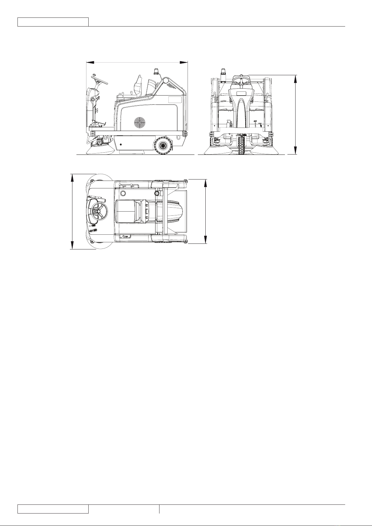
DIMENSIONS .................................................................................................................................................................................. 8
SCHEDULED MAINTENANCE ....................................................................................................................................................... 9
SCHEDULED MAINTENANCE TABLE ........................................................................................................................................... 9
MACHINE NOMENCLATURE ....................................................................................................................................................... 10
SWEEPING SYSTEM .................................................................................................................................................... 13
MAIN BROOM DRIVING BELT VISUAL INSPECTION................................................................................................................. 13
MAIN BROOM DRIVING BELT DISASSEMBLY/ASSEMBLY ....................................................................................................... 14
MAIN BROOM PULLEY BEARING REPLACEMENT ................................................................................................................... 15
MAIN BROOM GAS SPRING DISASSEMBLY/ASSEMBLY]......................................................................................................... 16
MAIN BROOM HEIGHT CHECK AND ADJUSTMENT.................................................................................................................. 17
MAIN BROOM REPLACEMENT ................................................................................................................................................... 19
MAIN BROOM HEIGHT ADJUSTMENT CABLE REPLACEMENT ............................................................................................... 20
SIDE BROOM HEIGHT ADJUSTMENT ........................................................................................................................................ 21
SIDE BROOM REPLACEMENT.................................................................................................................................................... 23
SIDE BROOM LIFTING CABLE REMOVAL .................................................................................................................................. 24
MICROSWITCH REPLACEMENT ON THE SIDE AND MAIN BROOMS LIFTING LEVERS ....................................................... 25
MAIN BROOM MOTOR ELECTRICAL INPUT CHECK................................................................................................................. 26
MAIN BROOM MOTOR CARBON BRUSH CHECK AND REPLACEMENT ................................................................................. 27
MAIN BROOM MOTOR DISASSEMBLY/ASSEMBLY................................................................................................................... 28
SIDE BROOM MOTOR ELECTRICAL INPUT CHECK ................................................................................................................. 29
SIDE BROOM MOTOR CARBON BRUSH CHECK AND REPLACEMENT.................................................................................. 30
SIDE BROOM MOTOR REMOVAL ............................................................................................................................................... 31
TROUBLESHOOTING................................................................................................................................................................... 32
SKIRT............................................................................................................................................................................. 33
SKIRT HEIGHT AND OPERATION CHECK .................................................................................................................................. 33
SIDE SKIRT REPLACEMENT ....................................................................................................................................................... 35
REAR SKIRT REPLACEMENT ..................................................................................................................................................... 35
FRONT SKIRT REPLACEMENT ................................................................................................................................................... 36
FRONT SKIRT CONTROL CABLE REPLACEMENT.................................................................................................................... 37
DUST AND DEBRIS COLLECTION SYSTEM .............................................................................................................. 39
PANEL DUST FILTER CLEANING AND INTEGRITY CHECK] ..................................................................................................... 39
CLOSED POCKET FILTER CLEANING AND INTEGRITY CHECK]............................................................................................. 41
VACUUM FAN MOTOR ELECTRICAL INPUT CHECK]................................................................................................................ 43
VACUUM FAN MOTOR REMOVAL/REPLACEMENT].................................................................................................................. 44
FILTER SHAKER OPERATION CHECK ....................................................................................................................................... 45
FILTER SHAKER MOTOR REMOVAL .......................................................................................................................................... 45
HOPPER GASKET CHECK AND REPLACEMENT ...................................................................................................................... 46
HORIZONTAL HOPPER CONTROL MICROSWITCH CHECK AND ADJUSTMENT ................................................................... 48
HORIZONTAL HOPPER CONTROL MICROSWITCH REPLACEMENT ...................................................................................... 49
LIFTED HOPPER CONTROL MICROSWITCH CHECK AND ADJUSTMENT.............................................................................. 50
LIFTED HOPPER CONTROL MICROSWITCH REPLACEMENT................................................................................................. 52
HOPPER ROTATION ACTUATOR CHECK AND ADJUSTMENT ................................................................................................. 53
HOPPER ROTATION ACTUATOR REPLACEMENT .................................................................................................................... 55
HOPPER MECHANICAL STABILIZER CHECK AND ADJUSTMENT ........................................................................................... 56
HOPPER REMOVAL ..................................................................................................................................................................... 57
ADJUSTMENT HOPPER END-OF-STROKE [SR 1301 B/SR 1301 P]......................................................................................... 58
HOPPER LIFTING LEVER ASSEMBLY REMOVAL...................................................................................................................... 60
TROUBLESHOOTING................................................................................................................................................................... 62

ENGLISH SERVICE MANUAL
21463546000(1)2008-07 Terra™ 5200
STEERING SYSTEM AND BRAKE SYSTEM ............................................................................................................... 63
STEERING CHAIN CHECK AND CLEANING............................................................................................................................... 63
STEERING CHAIN REPLACEMENT ............................................................................................................................................ 64
BRAKE SYSTEM ADJUSTMENT] ................................................................................................................................................. 65
BRAKE CONTROL CABLE REPLACEMENT ............................................................................................................................... 67
BRAKE REPLACEMENT............................................................................................................................................................... 69
DRIVE SYSTEM............................................................................................................................................................. 71
DRIVE SYSTEM MOTOR ELECTRICAL INPUT CHECK ............................................................................................................. 71
DRIVE SYSTEM MOTOR CARBON BRUSH CHECK AND REPLACEMENT.............................................................................. 73
DRIVE SYSTEM MOTOR REMOVAL............................................................................................................................................ 74
DRIVESHAFT BEARING REPLACEMENT ................................................................................................................................... 77
DRIVE CHAIN CLEANING AND TENSION CHECK ..................................................................................................................... 79
DRIVE CHAIN REPLACEMENT.................................................................................................................................................... 81
FORWARD/REVERSE GEAR PEDAL CONTROL BOARD REPLACEMENT .............................................................................. 83
TROUBLESHOOTING................................................................................................................................................................... 85
HOPPER HYDRAULIC LIFTING SYSTEM ................................................................................................................... 87
HYDRAULIC SYSTEM OIL CHANGE ........................................................................................................................................... 87
HOPPER LIFTING SYSTEM PUMP REMOVAL............................................................................................................................ 90
HOPPER LIFTING HYDRAULIC CYLINDER REMOVAL.............................................................................................................. 92
PUMP-TO-HYDRAULIC CYLINDER FEED AND/OR RETURN HOSES REMOVAL.................................................................... 94
COMPONENT LOCATION ............................................................................................................................................................ 96
HYDRAULIC DIAGRAM ................................................................................................................................................................ 97
OTHER SYSTEMS......................................................................................................................................................... 99
SCREW AND NUT TIGHTENING CHECK.................................................................................................................................... 99
ELECTRICAL SYSTEM ............................................................................................................................................... 101
BATTERY REMOVAL, INSTALLATION, MAINTENANCE AND CHARGING .............................................................................. 101
FUSE CHECK/REPLACEMENT/RESET..................................................................................................................................... 101
DRIVE SYSTEM ELECTRONIC BOARD REPLACEMENT ........................................................................................................ 102
TROUBLESHOOTING................................................................................................................................................................. 103
COMPONENT LOCATION .......................................................................................................................................................... 104
WIRING DIAGRAM...................................................................................................................................................................... 107

GENERAL INFORMATION
SERVICE MANUAL ENGLISH
Terra™ 5200 1463546000(1)2008-07 3
GENERAL INFORMATION
CONVENTIONS
Forward, backward, front, rear, left or right are intended with reference to the operator’s position, that is to say on the driver’s seat,
with the hands on the steering wheel.
MACHINE LIFTING
WARNING!
Do not work under the lifted machine without supporting it with safety stands.
MACHINE TRANSPORT
WARNING!
Before transporting the machine, make sure that:
All guards and hoods are closed.–
The ignition key is removed.–
The machine is securely fastened to the means of transport.–
PUSHING OR TOWING THE MACHINE
WARNING!
When pushing or towing the machine, carefully follow the instructions in the User Manual.
Failure to follow these instructions may cause damage to the machine.
OTHER REFERENCE MANUALS
The following Manuals are available at Advance Literature Service Department:
Terra™ 5200 Spare Parts List – Form Number 1463544000–
Terra™ 5200 User Manual – Form Number 1463545000–
Terra™ 5200P Roof Kit Assembly – Form Number 146 2097 000–
Terra™ 5200 Roof Pivoting Light Kit Assembly – Form Number 146 2099 000–
Terra™ 5200 Hood Pivoting Light Kit Assembly – Form Number 146 1156 000–
Terra™ 5200 Working Light Kit Assembly – Form Number 146 1713 000–
Terra™ 5200 Closed Pocket Filter Kit Assembly – Form Number 146 1235 000–
SAFETY
The following symbols indicate potentially dangerous situations. Always read this information carefully and take all necessary
precautions to safeguard people and property.
SYMBOLS
DANGER!
It indicates a dangerous situation with risk of death for the operator.
WARNING!
It indicates a potential risk of injury for people or damage to objects.
CAUTION!
It indicates a caution related to important or useful functions.
Pay careful attention to the paragraphs marked by this symbol.
NOTE
It indicates a remark related to important or useful functions.
CONSULTATION
It indicates the necessity to refer to the User Manual before performing any procedure.

GENERAL INFORMATION
ENGLISH SERVICE MANUAL
41463546000(1)2008-07 Terra™ 5200
GENERAL INSTRUCTIONS
Specic warnings and cautions to inform about potential damages to people and machine are shown below.
DANGER!
Before performing any maintenance, repair, cleaning or replacement procedure disconnect the battery–
connector, remove the ignition key and engage the parking brake.
This machine must be used by properly trained operators only. Children or disabled people cannot use this–
machine.
Keep sparks, ames and smoking materials away from the batteries. During the normal operation explosive –
gases are released.
Do not wear jewels when working near electrical components.–
Do not work under the lifted machine without supporting it with safety stands.–
When working under the open hood, ensure that it cannot be closed by accident.–
Do not operate the machine near toxic, dangerous, ammable and/or explosive powders, liquids or vapours. –
This machine is not suitable for collecting dangerous powders.
When lead batteries (WET) are installed on this machine, do not tilt the machine more than 30° from its–
horizontal position to not allow the highly corrosive acid to leak out of the batteries. When the machine is to
be tilted to perform maintenance procedures, remove the batteries.
If the machine is equipped with lead (WET) batteries, battery charging produces highly explosive hydrogen –
gas. Keep the hood open when charging the batteries and perform this procedure in well-ventilated areas
and away from naked ames.
WARNING!
Carefully read all the instructions before performing any maintenance/repair procedure.–
Take all necessary precautions to prevent hair, jewels and loose clothes from being caught by the machine–
moving parts.
To avoid any unauthorized use of the machine, remove the ignition key.–
Do not leave the machine unattended without being sure that it cannot move independently.–
Do not use the machine on slopes with a gradient exceeding the specications.–
Use only brooms supplied with the machine and those specied in the User Manual. Using other brooms –
could reduce safety.
Do not smoke while charging the batteries.–
Before using the machine, close all doors and/or covers.–
Do not use the machine in excessively dusty areas.–
Do not wash the machine with direct or pressurised water jets, or with corrosive substances.–
Do not use compressed air to clean this type of machine, except for the lters (see the relevant paragraph).–
While using this machine, take care not to cause damage to other people, and children especially.–
Do not put any can containing uids on the machine.–
The machine storage temperature must be between 32°F and 104°F (0°C and +40°C).–
The machine working temperature must be between32°F and 104°F (0°C and +40°C).–
The humidity must be between 30% and 95%.–
Always protect the machine against the sun, rain and bad weather, both under operation and inactivity–
condition. Store the machine indoors, in a dry place. This machine must be used in dry conditions, it must
not be used or kept outdoors in wet conditions.
Do not use the machine as a means of transport, or for pushing/towing.–
The machine maximum capacity, operator’s weight not included, is 242 lb (110 kg) (the weight of waste).–
Do not allow the brooms to operate while the machine is stationary to avoid damaging the oor.–
In case of re, possibly use a powder re extinguisher, not a water one.–
Do not bump into shelves or scaffoldings, especially where there is a risk of falling objects.–
Adjust the operation speed to suit the oor conditions.–
Do not use the machine on slopes with a gradient exceeding the specications.–
This machine cannot be used on roads or public streets.–
Do not tamper with the machine safety guards.–
Follow the routine maintenance procedures scrupulously.–
Do not remove or modify the plates afxed to the machine.–
In case of machine malfunctions, ensure that these are not due to lack of maintenance. Otherwise, request –
assistance from the authorised personnel or from an authorised Service Center.
If parts must be replaced, require ORIGINAL spare parts from an Authorised Dealer or Retailer.–
To ensure machine proper and safe operation, the scheduled maintenance shown in the relevant chapter of–
this Manual must be performed by the authorised personnel or by an authorised Service Center.
The machine must be disposed of properly, because of the presence of toxic-harmful materials (batteries, –
oils, plastics, etc.), which are subject to standards that require disposal in special centres (see the Scrapping
chapter).

GENERAL INFORMATION
SERVICE MANUAL ENGLISH
Terra™ 5200 1463546000(1)2008-07 5
TECHNICAL DATA
Dimensions and weights Values
Machine length 70 in (1,776 mm)
Machine width (with one side broom) 47.6 in (1,208 mm)
Machine width (with two side brooms) 51.6 in (1,310 mm)
Front – rear wheelbase 42.9 in (1,090 mm)
Track (centres of front wheels) 38.7 in (982.7 mm)
Machine maximum height (at the steering wheel) 53.1 in (1,350 mm)
Machine maximum height/with canopy/with canopy and pivoting light 54.1/80/83.8 in (1,375/2,030/2,130 mm)
Driver’s seat height 36.1 in (918.5 mm)
Minimum distance from the oor (skirts not included) 2.3 in (60 mm)
Approach angle 46% (25°)
Hopper maximum lifting height (horizontal position) 65 in (1,650 mm)
Minimum/maximum dumping height 10.6/54 in (270/1,370 mm)
Max overall height with the hopper lifted (HxLxW) 93.3 x 110.8 x 51.5 in
(2,370 x 2,816 x 1,310 mm)
Working width (with one side broom) 41.5 in (1,054 mm)
Working width (with two side brooms) 51.5 in (1,308 mm)
Main broom size (diameter x width) 11.8 x 31.5 in (300 x 800 mm)
Side broom diameter 19.7 in (500 mm)
Minimum turning radius 66.3 in (1,685 mm)
Rear wheel specic pressure on the oor (*) 159 psi (1.1 N/mm2)
Front wheel specic pressure on the oor (*) 159 psi (1.1 N/mm2)
Front axle weight in running conditions 659 lb (299 kg)
Rear axle weight in running conditions 934 lb (424 kg)
Machine kerb weight (with operator) 1594 lb (723 kg)
Front steering wheel (diameter x width) 12 x 3.6 in (305 x 92 mm)
Rear driving wheel (diameter x width) 12 x 3.6 in (305 x 92 mm)
(*) Machines have been tested under the following conditions:
With the operator [165 lb (75 kg)] on board•
Battery of maximum size installed•
Oil and fuel tanks lled up•
Optional components installed•
Weight on wheels checked•
Wheel print checked•
The result is expressed as maximum value for front wheel and for rear wheels•

GENERAL INFORMATION
ENGLISH SERVICE MANUAL
61463546000(1)2008-07 Terra™ 5200
Performance data Values
Maximum forward speed 4.3 mi/h (7 km/h)
Maximum reverse speed 2.1 mi/h (3.5 km/h)
Gradeability at full load 9° (16% )
Main broom maximum speed 550 rpm
Side broom maximum speed 85 rpm
Panel lter surface 5580 in2(3.6 m2)
Panel lter rating 15 ÷ 20 µ
Closed pocket lter surface 6510 in2(4.2 m2)
Closed pocket lter rating 40 ÷ 60 µ
Main broom compartment vacuum 0.015 psi (10.9 mm/H2O)
Maximum weight liftable by the hopper 242.5 lb (110 kg)
Hopper capacity 34,3 gal (130 litres)
Sound pressure level at workstation (ISO 11201, ISO 4871) (LpA) 67 dB(A) ±3 dB(A)
Machine output acoustic power (ISO 3744, ISO 4871) (LwA) 82 dB(A)
Vibration level at the operator’s body (ISO 2631-1) (**) < 98 in/s2(< 2.5 m/s2)
Vibration level at the operator’s arms (ISO 5349-1) (**) 256 in/s2(6.5 m/s2)
(**) Under normal working conditions, on a level asphalt surface.
Motor data Values
Electrical system voltage 24 V
Vacuum system motor Power 0.4 hp (310 W)
Revolutions per minute 3,000 rpm
Main broom motor Power 0.6 hp (500 W)
Revolutions per minute 550 rpm
Drive system motor Power 1 hp (750 W)
Revolutions per minute 315 rpm
Side broom reduction unit Power 0.12 hp (90 W)
Revolutions per minute 85 rpm
Panel lter shaker motor Power 0.12 hp (90 W)
Revolutions per minute 5,700 rpm
Closed pocket lter shaker motor Power 0.15 hp (110 W)
Revolutions per minute 3,000 rpm
Refuelling data Values
Hopper hydraulic lifting system Tank capacity [whole circuit] 0.2 gal (0.75 litres) [0.37 gal (1.4 litres)]
Oil type AGIP Arnica 46 (*)
(*) See the oil technical data and reference data tables below.
CAUTION!
If the machine is to be used at ambient temperatures below 50°F (10°C), the oil should be changed with
equivalent oil having a viscosity of 32 cSt. For temperatures below 32°F (0°C), use an oil with lower viscosity.

GENERAL INFORMATION
SERVICE MANUAL ENGLISH
Terra™ 5200 1463546000(1)2008-07 7
TECHNICAL DATA REFERENCE DATA
AGIP ARNICA 46 32 ISO-L-HV
Viscosity at 104 °F (40°C) in2/s (mm2/s) 0.07 (45) 0.05 (32) ISO 11158
Viscosity at 212 °F (100°C) in2/s (mm2/s) 0,012 (7.97) 0,009 (6.40) AFNOR NF E 48603 HV
Viscosity index / 150 157 AISE 127
Flash point COC °F (°C) 419 (215) 396 (202) ATOS Tab. P 002-0/I
Pour point °F (°C) -32.8 (-36) -32.8 (-36) BS 4231 HSE
Density at 59 °F (15°C) lb/gal (kg/l) 1.9 (0.87) 1.9 (0.865) CETOP RP 91 H HV
COMMERCIAL HYDRAULICS
Danieli Standard 0.000.001 (AGIP ARNICA 22, 46, 68)
EATON VICKERS I-286-S3
EATON VICKERS M-2950
DIN 51524 t.3 HVLP
LAMB LANDIS-CINCINNATI P68, P69, P70
LINDE
PARKER HANNIFIN (DENISON) HF-0
REXROTH RE 90220-1/11.02
SAUER-DANFOSS 520L0463
Electrical system data Values
System voltage 24 V
Propulsion battery
Standard WET batteries with acid electrolyte, in serial connection 4 x 6 V x 180 Ah@5h
Optional WET battery with acid electrolyte 1 x 24 V x 240 Ah@5h
Optional WET battery with acid electrolyte 1 x 24 V x 320 Ah@5h
Battery capacity 330 Ah@5h
Battery case dimensions 31.5 x 11.8 x 5.9 in (800 x 300 x 150 mm)
Battery compartment maximum size 14.2 x 31.5 x 14.9 in (360 x 800 x 380 mm)

GENERAL INFORMATION
ENGLISH SERVICE MANUAL
81463546000(1)2008-07 Terra™ 5200
DIMENSIONS
1776 mm (70.0 in)
1350 mm (53.1 in)
1106 mm (43.5 in)
1310 mm (51.6 in)
P100256

GENERAL INFORMATION
SERVICE MANUAL ENGLISH
Terra™ 5200 1463546000(1)2008-07 9
SCHEDULED MAINTENANCE
The lifespan of the machine and its maximum operating safety are ensured by proper and regular maintenance.
WARNING!
Before performing any maintenance procedure, carefully read the instructions shown in Safety chapter.
The following table provides the scheduled maintenance. The intervals shown may vary according to particular working conditions,
which are to be dened by the person in charge of the maintenance.
The following paragraphs give further instructions about maintenance procedures listed in the Scheduled Maintenance Table.
SCHEDULED MAINTENANCE TABLE
Procedure Upon delivery
Every
10
hours
Every
50
hours
Every
100
hours
Every
200
hours
Every
400
hours
Battery uid level check (1)
Side and main broom height check
Hopper hydraulic lifting system oil level check (1)
Skirt height and operation check
Panel dust lter cleaning and integrity check
Filter shaker operation check
Driving wheel chain cleaning and tension check
Visual inspection of the belt between motor and main broom
Closed pocket lter cleaning and integrity check
Brake adjustment
Nut and screw tightening check (2)
Steering chain cleaning
Vacuum system efciency check
Replacement of the timing belt between motor and main broom
Hopper gasket integrity check
Lifted hopper control microswitch adjustment check
Horizontal hopper control microswitch adjustment check
Motor carbon brush check and replacement
Hydraulic system oil change (3)
(1) Or before each start-up
(2) And after the rst 8 running-in hours
(3) Change the oil for the rst time after 500 hours, then every 2,000 hours or every year

GENERAL INFORMATION
ENGLISH SERVICE MANUAL
10 1463546000(1)2008-07 Terra™ 5200
MACHINE NOMENCLATURE
Throughout this Manual you will nd numbers in brackets – for example: (2). These numbers refer to the components shown in
these two nomenclature pages. Refer to these pages whenever it will be necessary to identify a component mentioned in the text.
Hopper lifting/lowering/dumping enabling switch1.
Horn switch2.
Working light switch (optional)3.
Main broom print adjusting knob4.
Turn it counter-clockwise to increase the broom print•
Turn it clockwise to decrease the broom print•
Position for optional switch5.
Switch6.
(Lower position) vacuum system activation•
(Upper position) lter shaker activation•
Hopper lifting/lowering switch7.
Hopper dumping switch8.
Display selection switch for the following functions, in9.
sequence:
Working hours•
Last digit of the hours - (dot) - minutes•
Battery voltage (V)•
Display10.
Discharged battery warning light (red)11.
Semi-discharged battery warning light (yellow)12.
Charged battery warning light (green)13.
Emergency push-button14.
Steering wheel15.
Steering wheel tilting control knob16.
Ignition key:17.
When turned to “0”, it turns the machine off and•
disables all functions.
When turned to “I”, it enables all machine functions; it•
also turns on the ashing light.
Parking brake lock control lever18.
It locks the service brake (75) thus switching it to parking
brake.
Forward/reverse gear pedal19.
Right side broom lifting/lowering lever20.
Left side broom lifting/lowering lever21.
Seat longitudinal position adjusting lever22.
Main broom lifting/lowering lever23.
Front skirt lifting pedal24.
Service brake pedal25.
Serial number plate/technical data/conformity certication28.
Flashing light (always on when the ignition key is turned to29.
“I”) (optional)
Vacuum system motor cover30.
Hopper (empty it when it is full)31.
Left door (to be opened for performing maintenance32.
procedures only)
Left closing fastener with safety mounting screw33.
Right door (for main broom removal)34.
Right fastener35.
Working light (optional)36.
Right side broom37.
Left side broom38.
Main broom39.
Battery compartment hood40.
Rear driving wheels on xed axle41.
Front steering wheel42.
Left side skirt43.
Right side skirt44.
Front skirt45.
Rear skirt46.
Dust lter container47.
Working light aiming adjusting screws48.
Battery compartment hood (open)49.
Lead batteries (WET) or optional gel batteries (GEL)50.
Battery caps (for WET batteries only)51.
Battery connector52.
Main broom motor circuit breaker53.
Right side broom motor circuit breaker54.
Left side broom motor circuit breaker55.
Lamellar fuse box56.
Vacuum system motor connector57.
Battery connection diagram58.
Drive system motor59.
Electrical component box60.
Drive system electronic board61.
Hopper hydraulic lifting system oil tank62.
Hood support rod63.
Driver’s seat64.

GENERAL INFORMATION
SERVICE MANUAL ENGLISH
Terra™ 5200 1463546000(1)2008-07 11
MACHINE NOMENCLATURE (Continues)
1 2
17
9
15
16 18
4
19
10
3 5 6 7 8
14
11 12 13
20 21
22
23
24
25
P100250
48
36
37 36 42 38 45 33 43 32 41
30
47
31
46 41 39 44 34 35
28
402964
94
94
P100251

GENERAL INFORMATION
ENGLISH SERVICE MANUAL
12 1463546000(1)2008-07 Terra™ 5200
MACHINE NOMENCLATURE (Continues)
P100252

SWEEPING SYSTEM
SERVICE MANUAL ENGLISH
Terra™ 5200 1463546000(1)2008-07 13
SWEEPING SYSTEM
MAIN BROOM DRIVING BELT VISUAL INSPECTION
Drive the machine on a level oor and engage the parking brake with the pedal and the lever (25 and 18).1.
Turn the ignition key (17) to “0”.2.
Release the fastener (33) and open the left door (32).3.
Visually inspect the timing belt (A) for integrity, cracks or breaks, along its whole length; if necessary, replace it (see the4.
procedure in the relevant paragraph).
Tension belt adjustment is not necessary.
Close the left side door (32) and engage the fastener (33).5.
A
P100258

SWEEPING SYSTEM
ENGLISH SERVICE MANUAL
14 1463546000(1)2008-07 Terra™ 5200
MAIN BROOM DRIVING BELT DISASSEMBLY/ASSEMBLY
Disassembly
Drive the machine on a level oor and engage the parking brake with the pedal and the lever (25 and 18).1.
Turn the ignition key (17) to “0”.2.
Lower the main broom lever (23).3.
Release the fastener (33) and open the left door (32).4.
With a wrench on the screw (A) turn the pulley (B) clockwise, and disengage the timing belt (C) from the pulley.5.
Remove the belt (C) from the pinion (D).6.
Assembly
Install the belt (C) on the pinion (D).7.
With a wrench on the screw (A) turn the pulley (B) clockwise, and engage the timing belt (C) to the pulley.8.
Tension belt adjustment is not necessary.9.
Close the left side door (32) and engage the fastener (33).10.
A
B
C
D
P100259

SWEEPING SYSTEM
SERVICE MANUAL ENGLISH
Terra™ 5200 1463546000(1)2008-07 15
MAIN BROOM PULLEY BEARING REPLACEMENT
Disassembly
Drive the machine onto an appropriate lifting hook.1.
Engage the parking brake with the pedal and the lever (25 and 18).2.
Turn the ignition key (17) to “0”.3.
Operating according to the safety rules, lift the machine.4.
If the lifting hook is not available, engage the machine to the four anchors (94), and lift it with a proper hoisting system,
operating according to the safety rules.
Remove the main broom (see the procedure in the relevant paragraph).5.
Release the fastener (33) and open the left door (32).6.
Remove the nut (A).7.
Remove the holder (B) and recover the key (C).8.
Remove the screw (D).9.
Remove the pulley (E) and recover the key (F).10.
Remove the main broom joint (G).11.
Remove the retaining ring (H).12.
Remove the main broom pulley bearings (I) with a hammer and a special bearing remover.13.
Assembly
Assemble the components in the reverse order of disassembly, and note the following:14.
Insert the new bearings (I) by pressing them only on the external ring and using a metal pipe with proper diameter.•
A
BCG
HI
FE
D
P100260

SWEEPING SYSTEM
ENGLISH SERVICE MANUAL
16 1463546000(1)2008-07 Terra™ 5200
MAIN BROOM GAS SPRING DISASSEMBLY/ASSEMBLY
Disassembly
Drive the machine onto an appropriate lifting hook.1.
Engage the parking brake with the pedal and the lever (25 and 18).2.
Turn the ignition key (17) to “0”.3.
Lower the main broom with the lever (23).4.
Remove the main broom (see the procedure in the relevant paragraph).5.
Fully turn the knob (4) counter-clockwise.6.
Operating according to the safety rules, lift the machine.7.
If the lifting hook is not available, engage the machine to the four anchors (94), and lift it with a proper hoisting system,
operating according to the safety rules.
Remove the fastening screws (A) and (B) of the gas spring (C).8.
Remove the gas spring (C) and recover the nuts and the washers (D).9.
Assembly
Assemble the components in the reverse order of disassembly, and note the following:10.
Tighten the screw (A) rst, then the screw (B).•
Adjust the main broom height (see the procedure in the relevant paragraph).11.
A
B
D
D
C
P100261

SWEEPING SYSTEM
SERVICE MANUAL ENGLISH
Terra™ 5200 1463546000(1)2008-07 17
MAIN BROOM HEIGHT CHECK AND ADJUSTMENT
NOTE
Brooms with harder or softer bristles are available. This procedure is applicable to all types of brooms.
Check
Check the main broom distance from the oor as shown below:1.
Drive the machine on a level oor.•
Keep the machine stationary, lower the main broom and turn it on for a few seconds.•
Stop and lift the main broom, then move the machine and switch it off.•
Check that the main broom print (A), along its length, is 0.8 to 1.6 in (2 to 4 cm) wide.•
If the print (A) is not within specications, adjust the main broom height according to the following procedure.
Adjustment of the overall broom pressure on the oor (the whole broom is too much or too little pressed to the
oor)
Turn the knob (B) and consider that:2.
To increase the print width, the knob must be turned counter-clockwise.•
To decrease the print width, lift the broom with the lever (80) and turn the knob clockwise.•
NOTE
The knob can be used both to adjust the print and to adjust the broom according to the bristle wear.
Perform step 1 again to check the proper adjustment of the main broom height.3.
When the broom is too worn to be adjusted, replace it (see the procedure in the relevant paragraph).4.
Adjustment of the pressure evenness across the broom length (the broom pressure differs from one end to another)
Release the fastener (35) and open the right door (34).5.
To adjust the broom pressure on the oor loosen the locknuts (C) and (D), and operate on the screws (E) and (F), and consider 6.
that: To lower the broom on the right side, the screw (E) must be tightened; to lift the broom on the right side the screw must be
loosened.
Then adjust the screw (F) until it ts on the inner bushing (G) and tighten the nuts (C) and (D).7.
Perform step 1 again to check the proper adjustment of the main broom pressure evenness on the oor.8.
Machine reset
Close the left door (32) and engage the fastener (33).9.
Close the right door (34) and engage the fastener (35).10.

SWEEPING SYSTEM
ENGLISH SERVICE MANUAL
18 1463546000(1)2008-07 Terra™ 5200
MAIN BROOM HEIGHT CHECK AND ADJUSTMENT (Continues)
B
P100216 P100262
P100263
Table of contents
Other Advance acoustic Blower manuals