Advance acoustic SW900 User manual

SW900
Instructions for use
Model No.:
9084112010
08/2013 Revised 01/2018
(C)
FORM NO. 1465374000
English
Français
Español
Português
Instructions d’utilisation
Instrucciones de uso
Instruções de uso
A0 COVER.indd 1 23/01/2018 11:08:53

A0 COVER.indd 2 23/01/2018 11:08:53

INSTRUCTIONS FOR USE ENGLISH
1465374000 - SW900 1
TABLE OF CONTENTS
INTRODUCTION.............................................................................................................................................................. 2
MANUAL PURPOSE AND CONTENTS .......................................................................................................................................... 2
TARGET........................................................................................................................................................................................... 2
HOW TO KEEP THIS MANUAL....................................................................................................................................................... 2
IDENTIFICATION DATA................................................................................................................................................................... 2
OTHER REFERENCE MANUALS................................................................................................................................................... 2
SPARE PARTS AND MAINTENANCE............................................................................................................................................. 2
CHANGES AND IMPROVEMENTS ................................................................................................................................................ 2
OPERATION CAPABILITIES ........................................................................................................................................................... 3
CONVENTIONS .............................................................................................................................................................................. 3
UNPACKING/DELIVERY ................................................................................................................................................. 3
SAFETY ........................................................................................................................................................................... 3
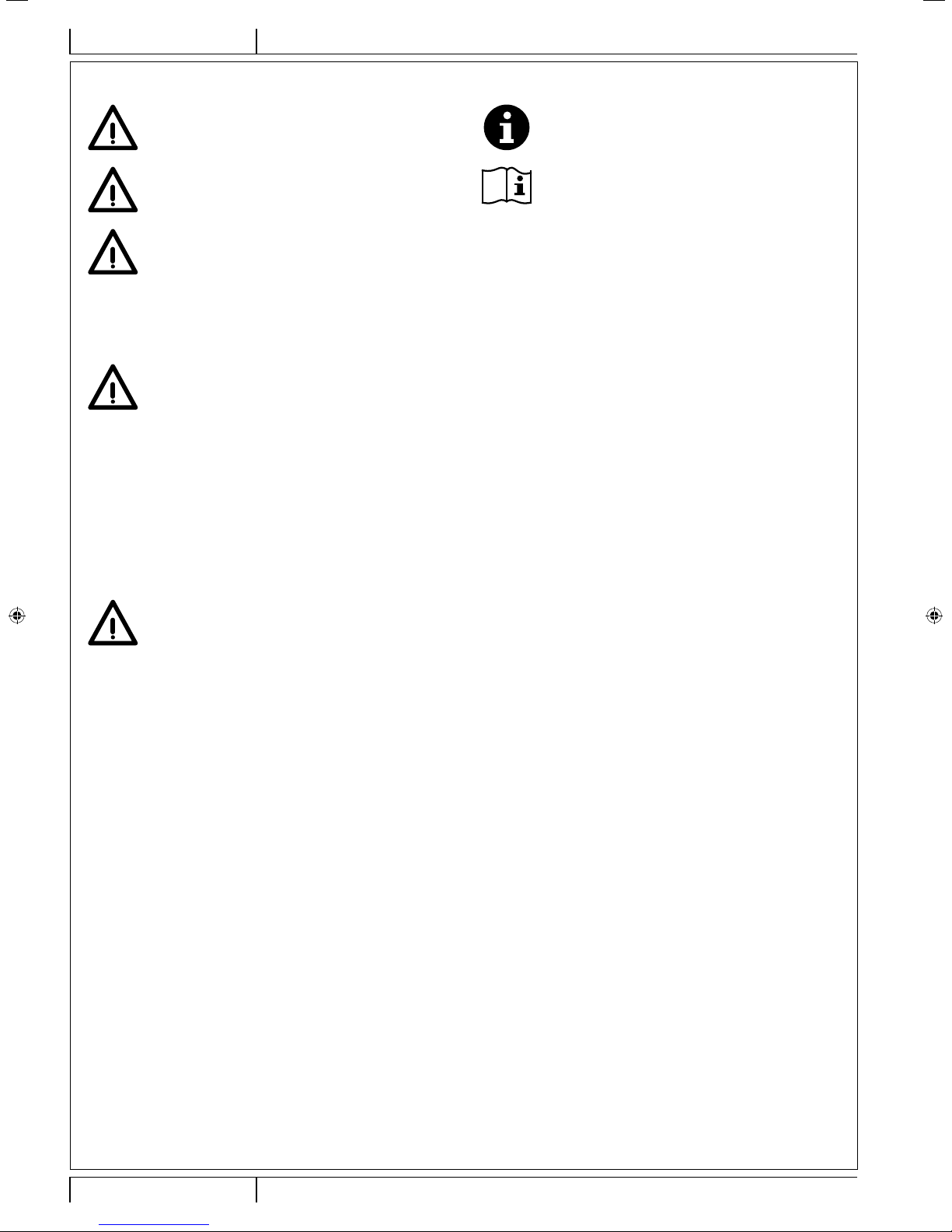
VISIBLE SYMBOLS ON THE MACHINE......................................................................................................................................... 3
SYMBOLS THAT APPEAR ON THIS MANUAL............................................................................................................................... 4
GENERAL INSTRUCTIONS............................................................................................................................................................ 4
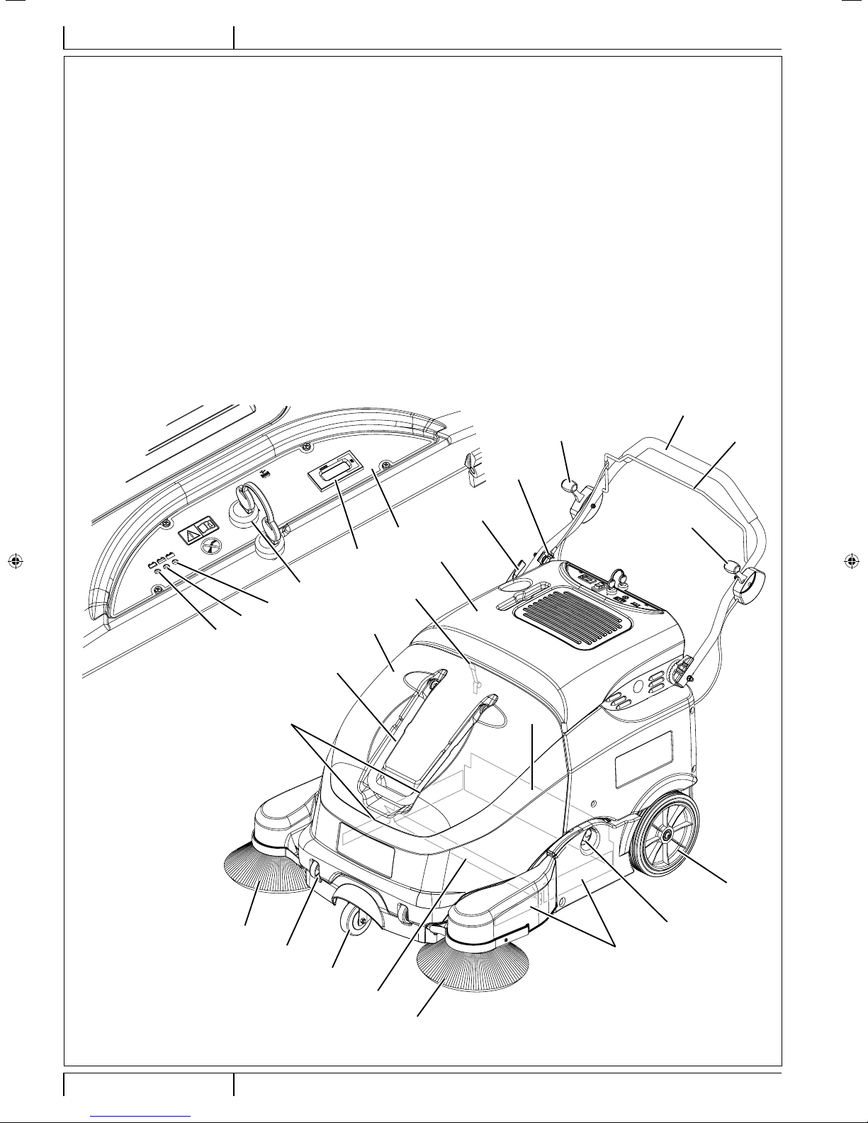
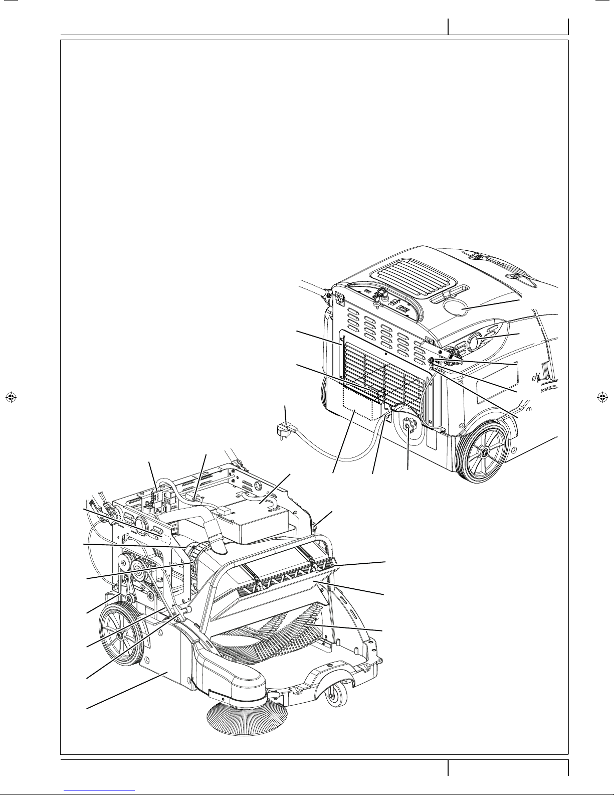
MACHINE DESCRIPTION ............................................................................................................................................... 6
MACHINE STRUCTURE ................................................................................................................................................................. 6
ACCESSORIES/OPTIONS.............................................................................................................................................................. 8
TECHNICAL DATA........................................................................................................................................................................... 8
WIRING DIAGRAM.......................................................................................................................................................................... 9
USE ................................................................................................................................................................................ 10
BATTERY CHECK/SETTING ON A NEW MACHINE.....................................................................................................................11
BEFORE MACHINE START-UP .................................................................................................................................................... 12
STARTING AND STOPPING THE MACHINE ............................................................................................................................... 12
MACHINE OPERATION ................................................................................................................................................................ 12
HOPPER DUMPING...................................................................................................................................................................... 13
AFTER USING THE MACHINE..................................................................................................................................................... 13
PUSHING THE MACHINE............................................................................................................................................................. 13
MACHINE LONG INACTIVITY ...................................................................................................................................................... 13
MAINTENANCE............................................................................................................................................................. 13
SCHEDULED MAINTENANCE TABLE ......................................................................................................................................... 14
BATTERY CHARGER CABLE CHECK ......................................................................................................................................... 14
BATTERY CHARGING .................................................................................................................................................................. 14
MAIN BROOM HEIGHT CHECK AND ADJUSTMENT.................................................................................................................. 15
MAIN BROOM REPLACEMENT ................................................................................................................................................... 16
SIDE BROOM HEIGHT CHECK AND ADJUSTMENT .................................................................................................................. 17
SIDE BROOM DISASSEMBLY/ASSEMBLY.................................................................................................................................. 17
SKIRT CHECK AND ADJUSTMENT ............................................................................................................................................. 18
DUST FILTER CLEANING AND INTEGRITY CHECK .................................................................................................................. 19
HOPPER POSITION MICROSWITCH OPERATION CHECK....................................................................................................... 20
FUSE CHECK/REPLACEMENT/RESET....................................................................................................................................... 20
BATTERY ELECTROLYTE LEVEL CHECK (FOR WET BATTERIES ONLY) ............................................................................... 20
TROUBLESHOOTING................................................................................................................................................... 21
SCRAPPING .................................................................................................................................................................. 22
1465374000(B)10-2013.indb 1 01/12/2017 15:00:05

ENGLISH INSTRUCTIONS FOR USE
2SW900 - 1465374000
INTRODUCTION
NOTE
The numbers in brackets refer to the components shown in Machine Description chapter.
MANUAL PURPOSE AND CONTENTS
The purpose of this Manual is to provide the operator with all necessary information to use the machine properly, in a safe and
autonomous way. It contains information about technical data, safety, operation, storage, maintenance, spare parts and disposal.
Before performing any procedure on the machine, the operators and qualied technicians must read this Manual carefully. Contact
Advance in case of doubts regarding the interpretation of the instructions and for any further information.
TARGET
This Manual is intended for operators and technicians qualied to perform the machine maintenance.
The operators must not perform procedures reserved for qualied technicians. Advance will not be responsible for damages coming
from failure to follow these instructions.
HOW TO KEEP THIS MANUAL
The Instructions for Use Manual must be kept near the machine, inside an adequate case, away from liquids and other substances
that can cause damage to it.
IDENTIFICATION DATA
The machine serial number and model name are marked on the plate (47).
Product code and year of production are marked on the same plate.
This information is useful when requiring machine spare parts. Use the following table to write down the machine identication data.
MACHINE model ...............................................................................
PRODUCT code ................................................................................
MACHINE serial number ...................................................................
OTHER REFERENCE MANUALS
– Electronic Battery Charger Manual (to be considered as integral part of this Manual)
– Spare Parts List (supplied with the machine)
Moreover, the following Manuals are available:
– Service Manual (that can be consulted at Advance Service Centers)
SPARE PARTS AND MAINTENANCE
All necessary operating, maintenance and repair procedures must be performed by qualied personnel or by Advance Service
Centers. Only original spare parts and accessories must be used.
Contact Advance for service or to order spare parts and accessories, specifying the machine model, product code and serial
number.
CHANGES AND IMPROVEMENTS
Advance constantly improves its products and reserves the right to make changes and improvements at its discretion without being
obliged to apply such benets to the machines that were previously sold.
Any change and/or addition of accessories must be approved and performed by Advance.
1465374000(B)10-2013.indb 2 01/12/2017 15:00:05

INSTRUCTIONS FOR USE ENGLISH
1465374000 - SW900 3
OPERATION CAPABILITIES
This sweeper has been designed to clean (by sweeping and vacuuming) smooth and solid oors, and to collect dust and light
debris, in civil and industrial environments, under safe operation conditions by a qualied operator.
CONVENTIONS
Forward, backward, front, rear, left or right are intended with reference to the operator’s position, that is to say with the hands on the
handlebar (10).
UNPACKING/DELIVERY
CAUTION!
To unpack the machine, carefully follow the instructions on the packing.
Upon delivery carefully check that the machine and its packing have not been damaged during transportation. In case of visible
damages, keep the packing and have it checked by the carrier that delivered it. Call the carrier immediately to ll in a damage claim.
Check that the machine is equipped with the following features:
– Technical documents:
• Sweeper Instructions for Use Manual (the present document)
• Electronic Battery Charger Manual
• Sweeper Spare Parts List
– No. 1 5 A fuse
SAFETY
The following symbols indicate potentially dangerous situations. Always read this information carefully and take all necessary
precautions to safeguard people and property.
The operator’s cooperation is essential in order to prevent injury. No accident prevention program is eective without the total
cooperation of the person responsible for the machine operation. Most of the accidents that may occur in a factory, while working
or moving around, are caused by failure to comply with the simplest rules for exercising prudence. A careful and prudent operator is
the best guarantee against accidents and is essential for successful completion of any prevention program.
VISIBLE SYMBOLS ON THE MACHINE
WARNING!
Carefully read all the instructions
before performing any operation on the
machine.
WARNING!
Do not wash the machine with direct or
pressurised water jets.
X
%
WARNING!
Do not use the machine on slopes with a
gradient exceeding the specications.
WARNING!
Moving parts.
1465374000(B)10-2013.indb 3 01/12/2017 15:00:06

ENGLISH INSTRUCTIONS FOR USE
4SW900 - 1465374000
SYMBOLS THAT APPEAR ON THIS MANUAL
DANGER!
It indicates a dangerous situation with risk of
death for the operator.
NOTE
It indicates a remark related to important or useful
functions.
WARNING!
It indicates a potential risk of injury for people or
damage to objects.
CONSULTATION
It indicates the necessity to refer to the Instructions
for Use Manual before performing any procedure.
CAUTION!
It indicates a caution or a remark related to
important or useful functions. Pay careful
attention to the paragraphs marked by this
symbol.
GENERAL INSTRUCTIONS
Specic warnings and cautions to inform about potential damages to people and machine are shown below.
DANGER!
–Before performing any cleaning, maintenance, repair or replacement procedure, remove the ignition key.
–This machine must be used by properly trained operators only.
–Do not wear jewels when working near electrical components.
–Do not work under the lifted machine without supporting it with safety stands.
–Do not operate the machine near toxic, dangerous, ammable and/or explosive powders, liquids or vapors:
This machine is not suitable for collecting dangerous powders.
–Keep the batteries away from sparks, ames and incandescent material. Explosive gases are released when
charging the batteries.
–If the machine is equipped with lead (WET) batteries, battery charging produces highly explosive hydrogen
gas. Charge the batteries in well-ventilated areas and away from naked ames.
–When lead batteries (WET) are installed, do not tilt the machine for more than 30° from the horizontal plane
to prevent the highly corrosive acid from leaking out of the batteries. When the machine is to be tilted to
perform maintenance procedures, remove the batteries.
WARNING!
–Carefully read all the instructions before performing any maintenance/repair procedure.
–Before using the battery charger, ensure that frequency and voltage values, indicated on the machine serial
number plate, match the electrical mains voltage.
–Do not pull or carry the machine by the battery charger cable and never use the battery charger cable as
a handle. Do not close a door on the battery charger cable, or pull the battery charger cable around sharp
edges or corners. Do not run the machine on the battery charger cable.
–Keep the battery charger cable away from heated surfaces.
–Do not use the machine if the battery charger cable or plug is damaged. If the machine is not working as it
should, has been damaged, left outdoors or dropped into water, return it to the Service Center.
–Before performing any maintenance procedure, disconnect the battery charger cable from the electrical
mains to avoid any risk of re, electric shock or injuries.
1465374000(B)10-2013.indb 4 01/12/2017 15:00:06

INSTRUCTIONS FOR USE ENGLISH
1465374000 - SW900 5
WARNING!
–Do not smoke while charging the batteries.
–This machine is not intended for use by persons (including children) with reduced physical, sensory or
mental capabilities, or lack of experience and knowledge, unless they have been given supervision or
instruction concerning use of the machine by a person responsible for they safety. Children should be
supervised to ensure that they do not play with the machine.
–Close attention is necessary when used near children.
–Use only as shown in this Manual. Use only Advance’s recommended accessories.
–Check the machine carefully before each use, always check that all the components have been assembled
before use. If the machine is not perfectly assembled it can cause damages to people and properties.
–Take all necessary precautions to prevent hair, jewels and loose clothes from being caught by the machine
moving parts.
–To avoid any unauthorised use of the machine, remove the ignition key.
–Do not leave the machine unattended without being sure that it cannot move independently.
–Do not use the machine on inclined surfaces.
–Do not tilt the machine more than the angle indicated on the machine itself, in order to prevent instability.
–Use only brooms supplied with the machine or those specied in the Instructions for Use Manual. Using
other brooms could reduce safety.
–Before using the machine, close all doors and/or covers, as indicated in the Instructions for Use Manual.
–Do not wash the machine with direct or pressurised water jets, or with corrosive substances.
–Use the machine only where a proper lighting is provided.
–While using this machine, take care not to cause damage to people or objects.
–Do not bump into shelves or scaoldings, especially where there is a risk of falling objects.
–Do not lean liquid containers on the machine, use the relevant can holder.
–The machine storage temperature must be 32°F to 104°F (0°C to +40°C).
–The machine working temperature must be 32°F to 104°F (0°C to +40°C).
–The humidity must be between 30% and 95%.
–Always protect the machine against the rain and bad weather, both under operation and inactivity condition.
Store the machine indoors, in a dry place. This machine must be used in dry conditions, it must not be used
or kept outdoors in wet conditions.
–Do not use the machine as a means of transport, or for pushing/towing.
–Do not allow the brooms to operate while the machine is stationary to avoid damaging the oor.
–The machine maximum capacity is 66 lb (30 kg) (the maximum weight of waste).
–In case of re, use a powder re extinguisher, not a water one.
–This machine cannot be used on roads or public streets.
–Do not tamper with the machine safety guards.
–Follow the routine maintenance procedures scrupulously.
–Do not allow any object to enter into the openings. Do not use the machine if the openings are clogged.
Always keep the openings free from dust, hairs and any other foreign material which could reduce the air
ow.
–Do not remove or modify the plates axed to the machine.
–In case of machine malfunctions, ensure that these are not due to lack of maintenance. If necessary,
request assistance from the authorised personnel or from an authorised Service Center.
–If parts must be replaced, require ORIGINAL spare parts from an Authorised Dealer or Retailer.
–To ensure machine proper and safe operation, the scheduled maintenance shown in the relevant chapter of
this Manual, must be performed by the authorised personnel or by an authorised Service Center.
–The machine must be disposed of properly, because of the presence of toxic-harmful materials (batteries,
oils, etc.), which are subject to standards that require disposal in special centres (see the Scrapping
chapter).
1465374000(B)10-2013.indb 5 01/12/2017 15:00:06

ENGLISH INSTRUCTIONS FOR USE
6SW900 - 1465374000
MACHINE DESCRIPTION
MACHINE STRUCTURE
1. Control panel
2. Ignition key:
• Position “0”: The machine is o and all functions are
disabled
• Position “I”: The machine is on and all functions are
enabled
4. Charged battery LED (green)
5. Semi-discharged battery LED (yellow)
6. Discharged battery LED (red)
7. Hour counter
8. Drive control lever
9. Drive system control adjuster
10. Handlebar
11. Handlebar tilting adjusting lever
12. Right side broom lifting/lowering lever
13. Left side broom lifting/lowering lever (optional)
14. Hopper
15. Hopper transport handle
16. Hopper wheels
17. Front pivoting wheel
18. Right side broom
19. Left side broom (optional)
20. Rear driving wheels
21. Battery and main motor hood
22. Front hood latch
23. Left door opening/closing knob
24. Front skirt
25. Rear skirt
26. Side skirts
6
5
4
2
7
1
10
8
9
13
12
11
16
14
15
19
17
18
20
21
22
25
26
23
24
26
P100813A
1465374000(B)10-2013.indb 6 01/12/2017 15:00:10

INSTRUCTIONS FOR USE ENGLISH
1465374000 - SW900 7
28
27
42
38
39
32
33
34
36
35
40
31
51 43
46
48
44
47
49
50
37
30
29
45
41
P100814A
MACHINE STRUCTURE (Continues)
27. Main broom
28. Main broom height adjusting knob
29. Battery fuse
30. Manual lter shaker activation handle
31. Battery charger fuse
32. Main motor circuit breaker
33. Right side broom motor circuit breaker
34. Left side broom motor circuit breaker (optional)
35. Batteries
36. Battery connector
37. Right door
38. Battery charger cable
39. Battery charger cable housing
40. Electronic battery charger
41. Dust lter
42. Pre-lter (optional)
43. “Wet by-pass” port
44. Main motor
45. Hopper position microswitch
46. Can holder
47. Serial number plate/technical data/conformity certication
48. Vacuum fan
49. Driving belt
50. Main broom belt
51. Rear grid
1465374000(B)10-2013.indb 7 01/12/2017 15:00:25

ENGLISH INSTRUCTIONS FOR USE
8SW900 - 1465374000
ACCESSORIES/OPTIONS
In addition to the standard components, the machine can be equipped with the following accessories/options, according to the
machine specic use:
– Left side broom
– Main and side brooms with harder or softer bristles
– Polyester dust lter
– Pre-lter
– Non-marking skirts
For further information concerning the optional accessories, contact an authorised Retailer.
TECHNICAL DATA
Model SW900 B
Cleaning width with one side broom 32.5 in (825 mm)
with two side brooms 41.3 in (1,050 mm)
Main broom size (length x diameter) 23.6 x 10.4 in (600 x 265 mm)
Side broom diameter 12.4 in (315 mm)
Theoretical working capacity with one side broom 39,987 ft2/h (3,715 m2/h)
with two side brooms 50,859 ft2/h (4,725 m2/h)
Hopper capacity 2.1 ft3(60 liters)
maximum transportable weight 66 lb (30 kg)
Filter cleaning system Manual lter shaker
area 20.5 ft2(1.9 m2)
ltering capacity 5-10 µm
Power Lead batteries for cyclic use / traction
12V (100 - 200 Ah C5)
Main motor power (drive/main broom/vacuum system) 0.9 hp (680 W)
Main broom speed 420 rpm
Side broom motor power 0.05 hp (40 W)
speed 100 rpm
Drive forward speed 2.8 mi/h (4.5 km/h)
Maximum gradient when working 2 %
Total absorbed power 67 A (0.8 kW)
Working autonomy 3 h
Size (length x width x height) machine running 54.7 x 34.2 x 43.3 in (1,390 x 870 x 1,100 mm)
machine with folded handlebar 41.3 x 34.2 x 33 in (1,050 x 870 x 840 mm)
machine with two side brooms 54.7 x 37.4 x 43.3 in (1,390 x 950 x 1,100 mm)
battery compartment 12.9 x 9 x 15 in (327 x 230 x 380 mm)
Weight kerb weight without batteries 181 lb (82 Kg)
total kerb weight (*) 315 lb (143 Kg)
gross vehicle weight (GVW) 388 lb (176 Kg)
Wheel specic pressure on the oor (front - rear wheels, in running conditions) 301 - 72 psi (2.1 - 0.5 N/mm2)
Sound pressure level at workstation (ISO 11201, ISO 4871, EN 60335-2-72) (LpA) 70 ± 3 dB(A)
Machine sound pressure level (ISO 3744, ISO 4871, EN 60335-2-72) (LwA) 84 dB(A)
IP protection class X3
U-turn space 61 in (1,550 mm)
Vibration level at the operator’s arms (ISO 5349-1) (**) < 98 in/s2(< 2.5 m/s2)
(*) With batteries and empty hopper.
(**) Under normal working conditions, on a level asphalt surface.
1465374000(B)10-2013.indb 8 01/12/2017 15:00:25

INSTRUCTIONS FOR USE ENGLISH
1465374000 - SW900 9
Machine material composition and recyclability
Type Recyclable
percentage
SW900 B weight percentage
Aluminium 100 % 2.4 %
Electric motors - various 29 % 11.8 %
Ferrous materials 100 % 39.4 %
Wiring harnesses 80 % 1.8 %
Liquids 100 % 0.0 %
Plastic - non-recyclable material 0 % 9.4 %
Plastic - recyclable material 100 % 27.1 %
Polyethylene 92 % 5.9 %
Rubber 20 % 2.4 %
Cardboard - paper - wood 100 % 28.6 %
WIRING DIAGRAM
Key
BAT 12 V batteries
CH Battery charger
EB1 Electronic board LED
F2 Battery charger fuse (30 A)
FA Main motor circuit breaker (70 A)
FB Right side broom circuit breaker (5 A)
FC Left side broom circuit breaker (5 A) (optional)
HM Hour counter
K0 Main motor electromagnetic switch
KEY Ignition key
M0 Main motor
M2 Right side broom motor
M3 Left side broom motor (optional)
SW0 Hopper microswitch
SW2 Right side broom microswitch
SW3 Left side broom microswitch (optional)
Color codes
BK Black
BU Blue
BN Brown
GN Green
GY Grey
OG Orange
PK Pink
RD Red
VT Violet
WH White
YE Yellow
1465374000(B)10-2013.indb 9 01/12/2017 15:00:25

ENGLISH INSTRUCTIONS FOR USE
10 SW900 - 1465374000
P100815A
USE
WARNING!
On some points of the machine there are some adhesive plates indicating:
–DANGER
–WARNING
–CAUTION
–CONSULTATION
While reading this Manual, the operator must pay particular attention to the symbols shown on the plates (see the Visible Symbols
On The Machine paragraph).
Do not cover these plates for any reason and immediately replace them if they are damaged.
1465374000(B)10-2013.indb 10 01/12/2017 15:00:26

INSTRUCTIONS FOR USE ENGLISH
1465374000 - SW900 11
BATTERY CHECK/SETTING ON A NEW MACHINE
WARNING!
The electric components of the machine can be seriously damaged if the batteries are either improperly installed
or connected. The batteries must be installed by qualied personnel only.
According to the type of batteries (WET or GEL-AGM), set the machine battery charger.
Check the batteries for damage before installation.
Disconnect the battery connector and the battery charger plug.
Handle the batteries with great care.
Install the battery terminal protection caps supplied with the machine.
The machine requires one 12 V battery, or two 6 V batteries connected according to the diagram in Figure 1.
The machine can be supplied in one of the following congurations:
a) WET or GEL batteries already installed on the machine
b) Without batteries
According to machine conguration, proceed as follows.
a) WET or GEL-AGM batteries already installed on the machine
1. Disengage the front latch (22) and open the battery and main motor hood (21), then check that the batteries are connected to
the machine with the connector (36).
2. Close the battery and main motor hood (21) and engage the front latch (22).
3. Insert the ignition key (2) on the control panel and turn it to “I” without pulling the drive control lever (8).
If the green LED (4) turns on, the batteries are ready to be used.
If the yellow or red LED (5 or 6) turns on, the batteries must be charged (see the procedure in Maintenance chapter).
b) Without batteries
1. Buy appropriate batteries (see the Technical Data paragraph and the
diagram in Figure 1).
For battery choice and installation, apply to qualied battery Retailers.
2. Disengage the front latch (22) and open the battery and main motor hood
(21).
3. Ensure that the battery connector (36) is disconnected.
WARNING!
The installed batteries may require a specic charging algorithm:
to set the most appropriate charging algorithm for the installed
batteries, always contact a qualied Advance Service Center.
4. Carefully lift the batteries to the relevant compartment, then place them as
shown in Figure 1.
5. Route and install the battery cable as shown in the diagrams in Figure 1,
then carefully tighten the nut on each battery terminal.
6. Place the protection cap on each terminal, then connect the battery
connector (36).
7. Close the battery and main motor hood (21) and engage the front latch (22).
8. Charge the batteries (see the procedure in Maintenance chapter).
BATTERY
PLUG
12V
6V
6V
BATTERY PLUG
P100816
Figure 1
1465374000(B)10-2013.indb 11 01/12/2017 15:00:26

ENGLISH INSTRUCTIONS FOR USE
12 SW900 - 1465374000
BEFORE MACHINE START-UP
1. Make sure that there are no open doors/hoods and that the machine is in normal operating conditions.
2. If the machine has not been used after being transported, check that all the blocks used for the transportation have been
removed.
3. Check that side and main brooms are installed, otherwise install them (see the procedure in Maintenance chapter).
4. Adjust the handlebar (10) as necessary, by using the lever (11).
When the adjustment is completed, close the lever.
STARTING AND STOPPING THE MACHINE
Starting the machine
1. Insert the ignition key (2) on the control panel and turn it to “I” without pulling the drive control lever (8).
During the rst 3 seconds, the battery LEDs (4, 5 and 6) ashing indicates the type of battery installed. Then, if the battery
charge is sucient, the main motor (44) turn on the main broom (27) and the vacuum fan (48).
If the green LED (4) turns on, the batteries are ready to be used.
If the yellow or red LED (5 or 6) turns on, the batteries must be charged (see the procedure in Maintenance chapter).
WARNING!
The machine cannot be started when the hopper (14) is not its position. A safety system prevents it from
starting.
2. Lower the side brooms (18) and (19, optional), by pulling the levers (12) and (13, optional) backwards.
NOTE
The side brooms turn on when lowered and can be lowered and lifted even when the machine is moving.
3. Start sweeping by grasping the handlebar (10) and pulling the drive control lever (8) gradually.
Stopping the machine
1. To stop the machine, release the drive control lever (8) completely.
2. To stop the side brooms (18) and (19, optional), pull the levers (12) and (13, optional) onwards.
3. To turn o the main broom (27) and the vacuum fan (48), turn the ignition key (2) to “0”.
4. Make sure that the machine cannot move independently.
MACHINE OPERATION
1. Drive the machine to the work area as shown in the previous paragraph.
2. Avoid stopping for a long time with the machine in the same position and the brooms turning: this could create unwanted
marks on the oor.
3. For machine proper operation, the dust lter (41) must be as clean as possible. For cleaning it, stop the machine and use the
handle (30) to activate the manual lter shaker.
NOTE
Repeat the lter shaking procedure at least every 10 minutes. This interval can change depending on the dustiness of
the area to be cleaned.
NOTE
When the dust lter is clogged and/or the hopper (14) is full, the machine cannot collect dust and debris anymore.
4. When operating on wet oors, open the “wet by-pass” port (43) to avoid damaging the dust lter.
When operating on dry oors, close the “wet by-pass” port (43) to restore proper vacuuming.
5. The hopper (14) should be emptied after each working cycle and whenever it is full.
NOTE
When the hopper is full, the machine cannot collect dust and debris anymore.
1465374000(B)10-2013.indb 12 01/12/2017 15:00:26

INSTRUCTIONS FOR USE ENGLISH
1465374000 - SW900 13
HOPPER DUMPING
1. Stop the machine and turn the ignition key (2) to “0”.
2. Remove the hopper (14) by using the transport handle (15) and the wheels (16) to drag it at the waste collection centre, then
empty it.
3. Reinstall the hopper on the machine.
4. The machine is ready to start sweeping again.
NOTE
When the hopper is removed, all machine functions are disabled.
AFTER USING THE MACHINE
After working, before leaving the machine, perform the following procedures.
– Turn on the manual lter shaker with the handle (30).
– Turn the ignition key (2) to “0” to stop the machine.
– Empty the hopper (14) (see the procedure in the previous paragraph).
– Lift the side brooms (18) and (19, optional), by pulling the levers (12) and (13, optional) onwards.
– Make sure that the machine cannot move independently.
– Charge the batteries (see the procedure in Maintenance chapter).
PUSHING THE MACHINE
The machine can be pushed both with the ignition key (2) to “0” and to “I”.
MACHINE LONG INACTIVITY
If the machine is not going to be used for more than 30 days, proceed as follows:
– Perform the procedures shown in After Machine Use paragraph.
– Check that the machine storage area is dry and clean.
– Disconnect the battery connector (36).
– Slightly lift the machine so that the skirts, the main broom and the wheels do not touch the ground.
MAINTENANCE
The lifespan of the machine and its maximum operating safety are ensured by correct and regular maintenance.
The following table provides the scheduled maintenance. The intervals shown may vary according to particular working conditions,
which are to be dened by the person in charge of the maintenance.
All scheduled or extraordinary maintenance procedures must be performed by qualied personnel, or by an authorised Service
Center.
This Manual describes only the easiest and most common maintenance procedures.
For other maintenance procedures shown in the Scheduled Maintenance Table, refer to the Service Manual that can be consulted
at any Service Center.
WARNING!
To perform maintenance procedures, the machine must be o, the ignition key removed, and, if necessary, the
batteries must be disconnected.
Read carefully the instructions in the Safety chapter before performing any maintenance procedure.
1465374000(B)10-2013.indb 13 01/12/2017 15:00:26

ENGLISH INSTRUCTIONS FOR USE
14 SW900 - 1465374000
SCHEDULED MAINTENANCE TABLE
Procedure Upon delivery Every 10
hours
Every 50
hours
Every 200
hours
Every 400
hours
Battery charging (1)
Battery (WET) uid level check
Battery charger cable check
Dust lter cleaning and integrity check (2)
Side and main broom height check and adjustment
Skirt height and operation check
Filter gasket check
Driving belt check/adjustment: drive system, main broom. (*)
Hopper position microswitch operation check
Driving belt replacement: drive system, main broom. (*)
Main motor carbon brush check or replacement (*)
(*) For the relevant procedure, refer to the Service Manual.
(1) Daily or after using the machine.
(2) Or before use.
BATTERY CHARGER CABLE CHECK
Carefully check the battery charger cable (38) and the relevant plug for wear, cuts, cracks or other damages.
If the battery charger cable or the relevant plug is damaged, contact the Advance Service Center.
BATTERY CHARGING
CAUTION!
Charge the batteries when the yellow (5) or red LED (6) turns on, or at the end of each cleaning cycle. Keeping
the batteries charged make their life last longer.
WARNING!
When the batteries are discharged, charge them as soon as possible, as that condition makes their life shorter.
WARNING!
If the machine is equipped with lead (WET) batteries, battery charging produces highly explosive hydrogen gas.
Charge the batteries in well-ventilated areas and away from naked ames.
Do not smoke while charging the batteries.
While charging the batteries always keep the hood open.
WARNING!
Pay careful attention when charging WET batteries as there may be battery uid leakages. The battery uid is
corrosive. If it comes in contact with skin or eyes, rinse thoroughly with water and consult a physician.
1. Drive the machine on a level oor. Make sure that the machine cannot move independently.
2. Turn the ignition key (2) to “0”.
3. Connect the cable (38) of the electronic battery charger (40) to the electrical mains.
WARNING!
The mains voltage and frequency must match the electronic battery charger values shown on the machine serial
number plate (47).
1465374000(B)10-2013.indb 14 01/12/2017 15:00:26

INSTRUCTIONS FOR USE ENGLISH
1465374000 - SW900 15
NOTE
When the electronic battery charger is connected to the electrical mains, all machine functions are automatically
disabled.
4. When the green LED (4) turns on, the batteries are charged.
For further information about the battery charger operation (40), see the Battery Charger Manual.
5. Disconnect the electronic battery charger cable (38) from the electrical mains and place it in its housing (39) on the machine.
6. Now the machine is ready to be used.
MAIN BROOM HEIGHT CHECK AND ADJUSTMENT
NOTE
Brooms with harder or softer bristles are available.
This procedure is applicable to all types of brooms.
Check
1. Check the main broom distance from the ground, according
to the following procedure:
2. Drive the machine on a level oor.
3. Keep the machine stationary and turn on the main broom
for a few seconds.
4. Stop the main broom, then move the machine and turn it
o.
5. Check that the main broom print (A, Fig. 2), along its
length, is 0.8 to 1.6 in (2 to 4 cm) wide.
6. If the print (A) is not within specications, adjust the broom
height.
Adjustment
7. Turn the ignition key (2) to “0”.
8. Turn the knob (B, Fig. 3) as shown below:
• to increase the print width, turn the knob counter-
clockwise
• to decrease the print width, turn the knob clockwise
NOTE
The knob can be used both to adjust the print and to
adjust the broom according to the bristle wear.
9. Perform step 1 again to check that the main broom is at the
correct distance from the ground.
10. When the broom is too worn to be adjusted, replace it as
shown in the next paragraph.
CAUTION!
If the main broom print is excessive (larger than
1.6 in (4 cm)), the machine regular operation
is aected and the moving parts or electrical
components can overheat, thus reducing
machine life.
Pay careful attention when performing the above-
mentioned checks, and always use the machine
according to the indicated conditions.
A
2 - 4 cm
0,8 - 1,6 in
P100817
Figure 2
B
P100818
Figure 3
1465374000(B)10-2013.indb 15 01/12/2017 15:00:26

ENGLISH INSTRUCTIONS FOR USE
16 SW900 - 1465374000
MAIN BROOM REPLACEMENT
CAUTION!
It is advisable to wear protective gloves when replacing the main broom because there can be sharp debris
between the bristles.
1. Drive the machine on a level oor.
2. Turn the ignition key (2) to “0”.
3. Turn the main broom height adjusting knob (28) fully clockwise.
4. Remove the hopper (14).
5. Turn the knob (23) and open the left door (A, Fig. 4).
6. Loosen the knobs (B) and remove the main broom cover (C) by slightly turning it counter-clockwise.
7. Remove the main broom (D) from the front side of the machine.
8. Check that the drive hub (E) is free from dirt or foreign materials (cords, rags, etc.) accidentally rolled up.
9. Place the new main broom with the bristles rows (F) bent as shown in the gure.
10. Install the new main broom on the front side of the machine, and ensure that the mesh (G) properly ts into the relevant drive
hub (E).
11. Install the main broom cover (C) and tighten the knobs (B).
12. Close the left door (A).
13. Adjust the main broom height as shown in the previous paragraph.
B
A
F
C
G
D
E
D
P100819
Figure 4
1465374000(B)10-2013.indb 16 01/12/2017 15:00:32

INSTRUCTIONS FOR USE ENGLISH
1465374000 - SW900 17
SIDE BROOM HEIGHT CHECK AND ADJUSTMENT
NOTE
Brooms with harder or softer bristles are available.
This procedure is applicable to all types of brooms.
NOTE
This procedure is applicable to both the right side
broom and left side broom (optional).
Check
1. Drive the machine on a level oor.
2. Turn the ignition key (2) to “I”.
3. Lower the side broom with the lever (12).
4. The proper side broom height is reached when the bristles
touch the oor along a circle arc as shown (A, Fig. 5).
If the print (A) is not within specications, adjust the broom
height.
Adjustment
5. Turn the ignition key (2) to “0”.
6. Loosen the nut (C, Fig. 6) under the cover (B) and turn the
screw (D) clockwise or counter-clockwise to increase or
decrease the side broom height. Then lock the screw with
the nut.
7. Perform step 4 again to check that the side broom is at the
correct distance from the ground.
8. When the broom is too worn to be adjusted, replace it as
shown in the next paragraph.
CAUTION!
If the side broom print is excessive, the machine
regular operation is aected and the moving
parts or electrical components can overheat, thus
reducing machine life.
A
P100820
Figure 5
CB D
P100821
Figure 6
SIDE BROOM DISASSEMBLY/ASSEMBLY
CAUTION!
It is advisable to wear protective gloves when
replacing the side broom because there can be
sharp debris between the bristles.
NOTE
This procedure is applicable to both the right side
broom and left side broom (optional).
1. Drive the machine on a level oor.
2. Turn the ignition key (2) to “0”.
3. Loosen the knob (A, Fig. 7) inside the side broom, then
remove the broom (B) by disengaging it from the three pins
(C).
4. Install the new broom on the machine engaging it on the
pins (C), then tighten the knob (A).
5. Adjust the height of the new broom according to the
procedure shown in the previous paragraph.
B A C CC
P100822
Figure 7
1465374000(B)10-2013.indb 17 01/12/2017 15:00:33

ENGLISH INSTRUCTIONS FOR USE
18 SW900 - 1465374000
SKIRT CHECK AND ADJUSTMENT
1. Drive the machine on a level oor that is suitable for
checking the skirt height. Make sure that the machine
cannot move independently.
2. Turn the ignition key (2) to “0”.
3. Remove the hopper (14).
4. Remove the main broom (27) as shown in the relevant
paragraph.
Side Skirt Check
5. Check the side skirts (26) for integrity.
Replace the skirts when they have cuts (A, Fig. 8) larger
than 20 mm or cracks/tears (B) larger than 10 mm (for skirt
replacement, refer to the Service Manual).
6. Check that the height of the side skirts (26) is as shown in
the gure (C), the side skirts must touch the oor all along
their length.
7. If necessary, adjust the skirts according to the following
procedure.
Side Skirt Adjustment
8. Remove the right door (52) to reach the nuts (D, Fig. 9).
9. Loosen the nuts (D) and the screw (E), then adjust the
height of the right side skirt (F) by using the slots of the
mounting holes.
10. Loosen the screws (G) and adjust the height of the right
side recovery skirt (H) by using the slots of the mounting
holes.
11. Loosen the screws (I) and the nuts (J), then adjust the
height of the left side skirt (K) by using the slots of the
mounting holes.
12. After that, tighten the screws and nuts.
NOTE
The adjustment procedure is applicable to both the
right side recovery skirt (H) and left side recovery
skirt (optional).
Front Skirt Check and Rear Skirt Check/Adjustment
13. On the hopper (14), check the front skirt (24) for integrity.
14. Check the rear skirt (25) for integrity.
15. Replace the skirts when they have cuts (A, Fig. 8) larger
than 20 mm or cracks/tears (B) larger than 10 mm (for skirt
replacement, refer to the Service Manual).
16. Check that the height of the rear skirt (25) is as shown in
the gure (C), the skirt must touch the oor all along its
length.
17. If necessary, loosen the screws (L, Fig. 10) and adjust the
height of the skirt (M) by using the slots of the mounting
holes.
18. When the adjustment is completed, tighten the screws (L).
19. Assemble the components in the reverse order of
disassembly.
NOTE
The front skirt (24) on the hopper does not require to
be adjusted.
> 20 mm
(> 0,8 in)
> 10 mm
(> 0,4 in)
A
B
C
P100823
Figure 8
G
EF
H
D
K
IJ
I
P100825
Figure 9
L
M
LLL
P100826
Figure 10
1465374000(B)10-2013.indb 18 01/12/2017 15:00:35
Table of contents
Languages:
Other Advance acoustic Blower manuals
Popular Blower manuals by other brands

DR.SCHNEIDER PC
DR.SCHNEIDER PC DC-003 Operation & maintenance instructions

Elektror
Elektror RD ATEX Customer's operating and assembly instructions

Tomcat
Tomcat VR operating instructions

Dunsch
Dunsch DU50040B3 instructions

Ryobi
Ryobi RBV2400CSV Original instructions

Elektror
Elektror HRD Series Operating and assembly instructions