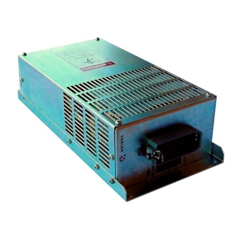
Advanced Energy Industries AMN PS-2A User manual

-~
ARTISAN
®
~I
TECHNOLOGY
GROUP
Your definitive source
for
quality
pre-owned
equipment.
Artisan Technology
Group
Full-service,
independent
repair
center
with
experienced
engineers
and
technicians
on staff.
We
buy
your
excess,
underutilized,
and
idle
equipment
along
with
credit
for
buybacks
and
trade-ins
.
Custom
engineering
so
your
equipment
works
exactly as
you
specify.
•
Critical
and
expedited
services
•
Leasing
/
Rentals/
Demos
• In
stock/
Ready-to-ship
•
!TAR-certified
secure
asset
solutions
Expert
team
ITrust
guarantee
I
100%
satisfaction
All
tr
ademarks,
br
a
nd
names, a
nd
br
a
nd
s a
pp
earing here
in
are
th
e property of
th
e
ir
r
es
pecti
ve
ow
ner
s.
Visit our website - Click HERE

U
S
ER
MANUAL
Fort Collins, CO 80525 USA
970.221.4670
1625 Sharp Point Drive
Advanced Energy Industries,Inc.
AMN PS-2A
Automatic Matching Network
Power Supply Controller
5708577-A
April 17, 2002


User Manual
AMN PS-2A
Automatic Matching Network Power Supply
Controller
5708577-A

iv 5708577-A
Advanced Energy®
COPYRIGHT
This manual and the information contained herein is the property of Advanced Energy
Industries, Inc.
No part of this manual may be reproduced or copied without the express written
permission of Advanced Energy Industries, Inc. Any unauthorized use of this manual
or its contents is strictly prohibited. Copyright ©2000 Advanced Energy Industries,
Inc. All Rights Reserved.
DISCLAIMER AND LIMITATION OF LIABILITY
The information contained in this manual is subject to change by Advanced Energy
Industries, Inc. without prior notice. Advanced Energy Industries, Inc. makes no
warranty of any kind whatsoever, either expressed or implied, with respect to the
information contained herein. Advanced Energy Industries, Inc. shall not be liable in
damages, of whatever kind, as a result of the reliance on or use of the information
contained herein.
PRODUCT USAGE STATEMENT
Read this entire manual and all other publications pertaining to the work to be
performed before you install, operate, or maintain this equipment. Practice all plant
and product safety instructions and precautions. Failure to follow instructions can
cause personal injury and/or property damage. All personnel who work with or who
are exposed to this equipment must take precautions to protect themselves against
serious or possibly fatal bodily injury.
Advanced Energy Industries, Inc., (AE) provides information on its products and
associated hazards, but it assumes no responsibility for the after-sale operation of
the equipment or the safety practices of the owner or user. This equipment produces
or uses potentially lethal high-voltage, high-current, radio frequency (RF) energy.
NEVER DEFEAT INTERLOCKS OR GROUNDS.

5708577-A v
AMN PS-2A
TRADEMARKS
is a registered trademark of Advanced Energy Industries, Inc.
Advanced Energy is a registered trademark of Advanced Energy Industries, Inc.
AE is a registered trademark of Advanced Energy Industries, Inc.

vi 5708577-A
Advanced Energy®

5708577-A vii
AMN PS-2A
Chapter 1. Introduction
Read This Section! . . . . . . . . . . . . . . . . . . . . . . . . . . . . . . . . . . . . . . . . . . . . . . . . . 1-1
Interpreting the Manual . . . . . . . . . . . . . . . . . . . . . . . . . . . . . . . . . . . . . . . . . . . . . 1-1
Type Conventions . . . . . . . . . . . . . . . . . . . . . . . . . . . . . . . . . . . . . . . . . . . . . . 1-1
Icons (Symbols) . . . . . . . . . . . . . . . . . . . . . . . . . . . . . . . . . . . . . . . . . . . . . . . 1-1
Safety . . . . . . . . . . . . . . . . . . . . . . . . . . . . . . . . . . . . . . . . . . . . . . . . . . . . . . . . . . . 1-3
Product Safety/Compliance . . . . . . . . . . . . . . . . . . . . . . . . . . . . . . . . . . . . . . . . . . 1-3
Directives and Standards . . . . . . . . . . . . . . . . . . . . . . . . . . . . . . . . . . . . . . . . 1-3
Certification . . . . . . . . . . . . . . . . . . . . . . . . . . . . . . . . . . . . . . . . . . . . . . . . . . . 1-4
Installation Requirements . . . . . . . . . . . . . . . . . . . . . . . . . . . . . . . . . . . . . . . . 1-4
Conditions of Use . . . . . . . . . . . . . . . . . . . . . . . . . . . . . . . . . . . . . . . . . . . . . . 1-4
Chapter 2. Theory
General Description . . . . . . . . . . . . . . . . . . . . . . . . . . . . . . . . . . . . . . . . . . . . . . . . 2-1
Theory of Operation . . . . . . . . . . . . . . . . . . . . . . . . . . . . . . . . . . . . . . . . . . . . . . . . 2-2
Chapter 3. Specifications
Physical Specifications . . . . . . . . . . . . . . . . . . . . . . . . . . . . . . . . . . . . . . . . . . . . . 3-1
Electrical Specifications . . . . . . . . . . . . . . . . . . . . . . . . . . . . . . . . . . . . . . . . . . . . . 3-1
Environmental Specifications . . . . . . . . . . . . . . . . . . . . . . . . . . . . . . . . . . . . . . . . . 3-3
Chapter 4. Controls, Indicators, and Interfaces
Remote Interface Connector (J2) . . . . . . . . . . . . . . . . . . . . . . . . . . . . . . . . . . . . . . 4-1
Remote Interface Connector (J2) Electrical Characteristics . . . . . . . . . . . . . . 4-1
Interface Cabling Requirements . . . . . . . . . . . . . . . . . . . . . . . . . . . . . . . . . . . 4-1
Remote Interface Connector (J2) . . . . . . . . . . . . . . . . . . . . . . . . . . . . . . . . . . 4-2
Matching Network Interface Connector (J1) . . . . . . . . . . . . . . . . . . . . . . . . . . . . . 4-3
Matching Network Interface Connector (J1) Electrical Characteristics . . . . . . 4-4
Interface Cabling Requirements . . . . . . . . . . . . . . . . . . . . . . . . . . . . . . . . . . . 4-4
Matching Network Interface Connector (J1) . . . . . . . . . . . . . . . . . . . . . . . . . . 4-4
Phase (J3) and Magnitude (J4) Error Voltage Input Ports . . . . . . . . . . . . . . . . . . . 4-6
Phase Error Voltage Input Port (J3) . . . . . . . . . . . . . . . . . . . . . . . . . . . . . . . . 4-6
Magnitude Error Voltage Input Port (J4) . . . . . . . . . . . . . . . . . . . . . . . . . . . . . 4-6
Phase/Magnitude Gain Adjustors . . . . . . . . . . . . . . . . . . . . . . . . . . . . . . . . . . . . . 4-7
Front Panel Switches and Indicators . . . . . . . . . . . . . . . . . . . . . . . . . . . . . . . . . . . 4-8
Rear View Illustration . . . . . . . . . . . . . . . . . . . . . . . . . . . . . . . . . . . . . . . . . . . . . . . 4-9
Table of Contents

viii 5708577-A
Advanced Energy®
Chapter 5. Installation, Setup, and Operation
Installing . . . . . . . . . . . . . . . . . . . . . . . . . . . . . . . . . . . . . . . . . . . . . . . . . . . . . . . . . 5-1
Unpacking . . . . . . . . . . . . . . . . . . . . . . . . . . . . . . . . . . . . . . . . . . . . . . . . . . . . 5-1
Grounding . . . . . . . . . . . . . . . . . . . . . . . . . . . . . . . . . . . . . . . . . . . . . . . . . . . . 5-1
Spacing Requirements . . . . . . . . . . . . . . . . . . . . . . . . . . . . . . . . . . . . . . . . . . 5-1
Dimensional Drawing . . . . . . . . . . . . . . . . . . . . . . . . . . . . . . . . . . . . . . . . 5-2
Mounting the Controller and Making Connections . . . . . . . . . . . . . . . . . . . . . 5-3
Electrical Verification . . . . . . . . . . . . . . . . . . . . . . . . . . . . . . . . . . . . . . . . . . . 5-4
Operation . . . . . . . . . . . . . . . . . . . . . . . . . . . . . . . . . . . . . . . . . . . . . . . . . . . . . . . . 5-4
Automatic Mode . . . . . . . . . . . . . . . . . . . . . . . . . . . . . . . . . . . . . . . . . . . . . . . 5-5
Manual Mode . . . . . . . . . . . . . . . . . . . . . . . . . . . . . . . . . . . . . . . . . . . . . . . . . 5-5
Remote Mode . . . . . . . . . . . . . . . . . . . . . . . . . . . . . . . . . . . . . . . . . . . . . . . . . 5-5
Chapter 6. Troubleshooting and Global Support
Before Calling AE Global Support . . . . . . . . . . . . . . . . . . . . . . . . . . . . . . . . . . . . . 6-1
Troubleshooting With the Power Off . . . . . . . . . . . . . . . . . . . . . . . . . . . . . . . . 6-1
Troubleshooting With the Power On . . . . . . . . . . . . . . . . . . . . . . . . . . . . . . . . 6-1
Troubleshooting Flow Chart . . . . . . . . . . . . . . . . . . . . . . . . . . . . . . . . . . . . . . 6-3
AE Global Support . . . . . . . . . . . . . . . . . . . . . . . . . . . . . . . . . . . . . . . . . . . . . . . . . 6-4
Returning Units for Repair . . . . . . . . . . . . . . . . . . . . . . . . . . . . . . . . . . . . . . . . . . . 6-5
Warranty . . . . . . . . . . . . . . . . . . . . . . . . . . . . . . . . . . . . . . . . . . . . . . . . . . . . . . . . 6-5
Authorized Returns . . . . . . . . . . . . . . . . . . . . . . . . . . . . . . . . . . . . . . . . . . . . . 6-6
Warranty Statement . . . . . . . . . . . . . . . . . . . . . . . . . . . . . . . . . . . . . . . . . . . . 6-6

5708577-A ix
AMN PS-2A
Theory of Operation Block Diagram . . . . . . . . . . . . . . . . . . . . . . . . . . . . . . . . . . . . . . . 2-2
Wiring for 115 Vac transformer . . . . . . . . . . . . . . . . . . . . . . . . . . . . . . . . . . . . . . . . . . . 3-2
Wiring for 230 Vac Transformer . . . . . . . . . . . . . . . . . . . . . . . . . . . . . . . . . . . . . . . . . . 3-3
Remote Interface Connector (J2) . . . . . . . . . . . . . . . . . . . . . . . . . . . . . . . . . . . . . . . . . 4-2
Matching Network Interface Connector (J1) . . . . . . . . . . . . . . . . . . . . . . . . . . . . . . . . . 4-4
Phase Error Voltage Input Port (J3) . . . . . . . . . . . . . . . . . . . . . . . . . . . . . . . . . . . . . . . 4-6
Magnitude Error Voltage Input Port (J4) . . . . . . . . . . . . . . . . . . . . . . . . . . . . . . . . . . . . 4-6
Phase and Magnitude Gain Adjustments on Rear Panel . . . . . . . . . . . . . . . . . . . . . . . 4-7
AMN PS-2A Controller Front Panel . . . . . . . . . . . . . . . . . . . . . . . . . . . . . . . . . . . . . . . . 4-8
Rear View . . . . . . . . . . . . . . . . . . . . . . . . . . . . . . . . . . . . . . . . . . . . . . . . . . . . . . . . . . .4-9
Dimensions . . . . . . . . . . . . . . . . . . . . . . . . . . . . . . . . . . . . . . . . . . . . . . . . . . . . . . . . . . 5-2
Matching Network Interface Connector (J1) . . . . . . . . . . . . . . . . . . . . . . . . . . . . . . . . . 5-3
Remote Interface Connector (J2) . . . . . . . . . . . . . . . . . . . . . . . . . . . . . . . . . . . . . . . . . 5-3
BNC-Type Connector (J3 and J4) . . . . . . . . . . . . . . . . . . . . . . . . . . . . . . . . . . . . . . . . . 5-4
List of Figures

x5708577-A
Advanced Energy®

5708577-A xi
AMN PS-2A
Electromagnetic Compatibility (EMC) . . . . . . . . . . . . . . . . . . . . . . . . . . . . . . . . . . . . . . 1-3
Safety . . . . . . . . . . . . . . . . . . . . . . . . . . . . . . . . . . . . . . . . . . . . . . . . . . . . . . . . . . . . . . 1-3
Physical Specifications . . . . . . . . . . . . . . . . . . . . . . . . . . . . . . . . . . . . . . . . . . . . . . . . . 3-1
Electrical Specifications . . . . . . . . . . . . . . . . . . . . . . . . . . . . . . . . . . . . . . . . . . . . . . . . 3-1
Climatic Specifications per EN 50178 and EN 60721 . . . . . . . . . . . . . . . . . . . . . . . . . . 3-4
Environmental Specifications . . . . . . . . . . . . . . . . . . . . . . . . . . . . . . . . . . . . . . . . . . . . 3-4
Remote Interface Connector Signal Types . . . . . . . . . . . . . . . . . . . . . . . . . . . . . . . . . . 4-1
Remote Interface Connector (J2) Pin Descriptions . . . . . . . . . . . . . . . . . . . . . . . . . . . . 4-2
Matching Network Interface Connector Signal Types . . . . . . . . . . . . . . . . . . . . . . . . . . 4-4
Matching Network Interface Connector (J1) Pin Descriptions . . . . . . . . . . . . . . . . . . . . 4-5
Front Panel Controls and Indicators . . . . . . . . . . . . . . . . . . . . . . . . . . . . . . . . . . . . . . . 4-8
Global Support . . . . . . . . . . . . . . . . . . . . . . . . . . . . . . . . . . . . . . . . . . . . . . . . . . . . . . . 6-4
List of Tables

xii 5708577-A
Advanced Energy®

5708577-A 1-1
Chapter
AMN PS-2A Chapter
1
1Introduction
READ THIS SECTION!
To ensure safe operation, you should read and understand this manual before you
attempt to install or operate this unit. At a minimum, read and heed the “Safety”
section in this chapter.
INTERPRETING THE MANUAL
The following sections describe the type conventions in the manual as well as the
icons and symbols you may see in the manual.
Type Conventions
To help you quickly find what is being discussed, the manual presents certain words
and phrases in type that is different from the rest of the text. We use the following type
conventions:
• Pin and signal names appear in capitalized italics (DUTY CYCLE.A).
• Labels that are on the unit (switches, indicators, etc.) generally appear in boldface
capital letters (MODIFY); however they appear as you see them on the unit.
Exceptions are port names, which simply begin with a capital letter (User port).
• Commands (162) and command names (setpoint) appear in boldface lowercase
letters.
Icons (Symbols)
This symbol represents important notes concerning potential harm to
people, this unit, or associated equipment. It is found whenever
needed in the manual.
We include this symbol in Danger, Warning, and Caution boxes to identify specific
levels of hazard seriousness.
This box identifies hazards that could result in severe personal injury or
death.

1-2 5708577-A
Advanced Energy®
The following symbols could appear on labels on your unit.
This box identifies hazards or unsafe practices that could result in
personal injury.
This box identifies hazards or unsafe practices that could result in
product or property damage.
Hazardous Voltage
High voltage
CE label
Warning (refer to manual)

5708577-A 1-3
AMN PS-2A
SAFETY
Do not attempt to install or operate this equipment if you have not first acquired
proper training.
• Ensure that this unit is properly grounded.
• Ensure that all cables are properly connected.
• Verify that input line voltage and current capacity are within specifications before
turning on the power supplies.
• Use proper ESD precautions.
• BE CAREFUL AROUND THIS EQUIPMENT
PRODUCT SAFETY/COMPLIANCE
Certain options of this unit have been tested for and comply with the following:
Directives and Standards
The following tables list the Electromagnetic Compatibility (EMC) and Safety
directives and standards.
Table 1-1. Electromagnetic Compatibility (EMC)
Directive or
Standard
Description
89/336/EEC EC Council directive on the approximation of the laws of the
Member States relating to electromagnetic compatibility (EMC
Directive).
EN 61000-6-2 Electromagnetic Compatibility– Generic Standards— Immunity
for Industrial Environment
EN 55011 Limits and Methods of Measurement of Radio Disturbance
Characteristics of Industrial, Scientific, Medical (ISM) Radio
Frequency Equipment (Class A, Group 2) (CISPR 11).
Table 1-2. Safety
Directive or
Standard
Description
73/23/EEC EC Council directive on the harmonization of the laws of the
Member States relating to electrical equipment designed for use
within certain voltage limits (LVD - Low Voltage Directive).
EN61010-1 Safety requirements for electrical equipment for measurement,
control, and laboratory use.

1-4 5708577-A
Advanced Energy®
This device must be installed and used only in compliance with the standards listed
and applicable requirements.
Certification
Certain options of this product are certified by:
• CE marking is self addressed by AE Compliance Engineering
• EMC measurements verified by UNISYS PCTC.
For more information, refer to the letter of conformance (US) or declaration of
conformity (EU) accompanying the product.
Installation Requirements
Conditions of Use
To be in compliance with the stated directives and standards, you must meet the
following conditions of use.
• Install and operate this device in an overvoltage category II installation only.
• Install and operate this device only in a pollution degree 2 or better environment,
which means an indoor location such as a computer room, office, or factory floor
where only non-conductive pollution occurs during operation. Occasionally, a
temporary conductivity caused by condensation occurs when the device is not
operating.
Operating and maintenance personnel must receive proper training
before installing, troubleshooting, or maintaining high-energy electrical
equipment. Potentially lethal voltages could cause death, serious
personal injury, or damage to the equipment. Ensure that all appropriate
safety precautions are taken.
RISK OF DEATH OR BODILY INJURY. Disconnect all sources of input
power before working on this unit or anything connected to it.

5708577-A 1-5
AMN PS-2A
• For units with captive line cord, you must install and operate this device with a
disconnect switch that conforms to the applicable requirements. The switch must
be easily accessible and near the device.
• Install this device so that the input power connection is inaccessible to the user
• Terminate the ac line cord according to the applicable requirements.
• Use only shielded cables on the remote interface and matching network interface
connectors.

1-6 5708577-A
Advanced Energy®

5708577-A 2-1
Chapter
AMN PS-2A Chapter
2
2Theory
The following sections provide a general description of the Automatic Matching
Network Power Supply 2A (AMN PS-2A) controller and a theory of how the
controller operates.
GENERAL DESCRIPTION
The AMN PS-2A controller monitors and controls the positions of the load and tune
capacitors within the AM family of matching network products, including the AM5,
AM10, AM20, AM30, AM50, AM100, AM150, and AM250.
The AMN PS-2A is completely self contained, and it provides all necessary circuitry
for controlling the servomotor system in matching networks without internal
controllers.
The AMN PS-2A controller can be purchased in versions that use either 115 Vac or
230 Vac source power. These versions are also available with a 12 Vdc external fan
option. The external fan option provides +12 Vdc for an external fan, which is
mounted onto and provides additional cooling for the matching network. This voltage
is provided through pins 14 (+12 Vdc) and 15 (ground) of the matching network
connector (J1).
The indicators and meters on the front panel of the AMN PS-2A allow the user to
monitor controller status information, including:
• Power on/off
• Failure status
• Tune and load capacitor positions
• Tune and load capacitor minimum limits
• Tune and load capacitor maximum limits
The AMN PS-2A provides flexibility by offering three modes with which the user can
operate the matching network load and tune servomotors:
•Inautomatic mode, the matching network’s phase and magnitude detectors
actively control the servomotor speed and direction of travel.
•Inmanual mode, the user manually controls the servomotors through the
momentary switches (labeled “-” and “+”) on the AMN PS-2A front panel.
•Inremote mode, a user-supplied external 0 to 5 Vdc signal controls the position
of the servomotors (through the remote interface on the AMN PS-2A).
Table of contents
