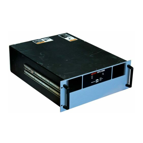
Advanced Energy RFG 1251 User manual

Advanced Energy Industries, Inc.
1625 Sharp Point Drive Fort Collins, CO 80525 USA
970.221.4670 support@ftc1.aei.com
RFG 1251 Generator
User Manual
5706058-A
August 1999


User Manual
RFG 1251 Generator
5706058-A

Read this entire manual and all other publications pertaining to the work to be performed
before you install, operate, or maintain this equipment. Practice all plant and product safety
instructions and precautions. Failure to follow instructions can cause personal injury and/or
property damage. All personnel who work with or who are exposed to this equipment must
take precautions to protect themselves against serious or possibly fatal bodily injury.
Advanced Energy Industries, Inc., (AE) provides information on its products and associated
hazards, but it assumes no responsibility for the after-sale operation of the equipment or the
safety practices of the owner or user. This equipment produces or uses potentially lethal high-
voltage, high-current, radio frequency (RF) energy. NEVER DEFEAT INTERLOCKS OR
GROUNDS.
All information herein is subject to periodic updates. Inquiries concerning this manual should
be directed to AE. Information provided by AE is believed to be correct and reliable.
However, no responsibility is assumed by AE unless otherwise expressly taken.
is a registered trademark of Advanced Energy Industries, Inc.
Advanced Energy is a registered trademark of Advanced Energy Industries, Inc.
Apex is a trademark of Advanced Energy Industries, Inc.
Arc-Check is a trademark of Advanced Energy Industries, Inc.
Arc-Out is a trademark of Advanced Energy Industries, Inc.
Astral is a trademark of Advanced Energy Industries, Inc.
Crystal is a trademark of Advanced Energy Industries, Inc.
FixedMatch is a registered trademark of Advanced Energy Industries, Inc.
GenCal is a trademark of Advanced Energy Industries, Inc.
Matchless is a trademark of Advanced Energy Industries, Inc.
Microsweep is a registered trademark of Advanced Energy Industries, Inc.
Pinnacle is a trademark of Advanced Energy Industries, Inc.
Sparc is a registered trademark of Advanced Energy Industries, Inc.
Sparc-le is a registered trademark of Advanced Energy Industries, Inc.
Sparc-vs is a trademark of Advanced Energy Industries, Inc.
Starburst is a trademark of Advanced Energy Industries, Inc.
SwitchMatch is a trademark of Advanced Energy Industries, Inc.
Z-Scan is a trademark of Advanced Energy Industries, Inc.
Z-Ware is a trademark of Advanced Energy Industries, Inc.
1998 © Copyright by Advanced Energy Industries Inc. All rights reserved. Without written
permission, no part of this manual covered by copyright herein may be reproduced or copied
in any form or by any means: graphic, electronic, or mechanical, including photocopying,
recording, taping, or information and retrieval systems. Written permission must be granted
by:
Advanced Energy Industries, Inc.
1625 Sharp Point Drive
Fort Collins, Colorado 80525 USA
WARNING

5706058-A Table of Contents vii
RFG 1251 Generator
Chapter 1. Introduction . . . . . . . . . . . . . . . . . . . . . . . . . . . . . . . . . . . . . . . . . . . . . . . . . . 1-1
Read This Section!. . . . . . . . . . . . . . . . . . . . . . . . . . . . . . . . . . . . . . . . . . . . . 1-1
Interpreting the Manual . . . . . . . . . . . . . . . . . . . . . . . . . . . . . . . . . . . . . . . . . 1-1
Type Conventions. . . . . . . . . . . . . . . . . . . . . . . . . . . . . . . . . . . . . . . . . . . . 1-1
Icons (Symbols) . . . . . . . . . . . . . . . . . . . . . . . . . . . . . . . . . . . . . . . . . . . . . 1-1
Safety . . . . . . . . . . . . . . . . . . . . . . . . . . . . . . . . . . . . . . . . . . . . . . . . . . . . . . . 1-3
Product Safety/Compliance . . . . . . . . . . . . . . . . . . . . . . . . . . . . . . . . . . . . . . 1-4
Directives . . . . . . . . . . . . . . . . . . . . . . . . . . . . . . . . . . . . . . . . . . . . . . . . . . 1-4
Standards. . . . . . . . . . . . . . . . . . . . . . . . . . . . . . . . . . . . . . . . . . . . . . . . . . . 1-4
Installation Requirements. . . . . . . . . . . . . . . . . . . . . . . . . . . . . . . . . . . . . . 1-5
Conditions of Use . . . . . . . . . . . . . . . . . . . . . . . . . . . . . . . . . . . . . . . . . . . . 1-5
Chapter 2. Theory . . . . . . . . . . . . . . . . . . . . . . . . . . . . . . . . . . . . . . . . . . . . . . . . . . . . . . . 2-1
General Description . . . . . . . . . . . . . . . . . . . . . . . . . . . . . . . . . . . . . . . . . . . . 2-1
Theory of Operation. . . . . . . . . . . . . . . . . . . . . . . . . . . . . . . . . . . . . . . . . . . . 2-1
Chapter 3. Specifications . . . . . . . . . . . . . . . . . . . . . . . . . . . . . . . . . . . . . . . . . . . . . . . . . 3-1
Physical Specifications . . . . . . . . . . . . . . . . . . . . . . . . . . . . . . . . . . . . . . . . . 3-1
Electrical Specifications. . . . . . . . . . . . . . . . . . . . . . . . . . . . . . . . . . . . . . . . . 3-1
Environmental Specifications . . . . . . . . . . . . . . . . . . . . . . . . . . . . . . . . . . . . 3-3
Chapter 4. Connectors, Indicators, and Controls . . . . . . . . . . . . . . . . . . . . . . . . . . . . . 4-1
User Port . . . . . . . . . . . . . . . . . . . . . . . . . . . . . . . . . . . . . . . . . . . . . . . . . . . . 4-1
Interface Cabling Requirements . . . . . . . . . . . . . . . . . . . . . . . . . . . . . . . . . 4-5
Interface Schematics. . . . . . . . . . . . . . . . . . . . . . . . . . . . . . . . . . . . . . . . . . 4-5
Water Control Connector. . . . . . . . . . . . . . . . . . . . . . . . . . . . . . . . . . . . . . . . 4-6
AC Power Connector. . . . . . . . . . . . . . . . . . . . . . . . . . . . . . . . . . . . . . . . . . . 4-6
Status Indicators. . . . . . . . . . . . . . . . . . . . . . . . . . . . . . . . . . . . . . . . . . . . . . . 4-7
Connector Panel. . . . . . . . . . . . . . . . . . . . . . . . . . . . . . . . . . . . . . . . . . . . . . . 4-9
Chapter 5. Installation . . . . . . . . . . . . . . . . . . . . . . . . . . . . . . . . . . . . . . . . . . . . . . . . . . . 5-1
Setting Up . . . . . . . . . . . . . . . . . . . . . . . . . . . . . . . . . . . . . . . . . . . . . . . . . . . 5-1
Unpacking. . . . . . . . . . . . . . . . . . . . . . . . . . . . . . . . . . . . . . . . . . . . . . . . . . 5-1
Table of Contents

viii Table of Contents 5706058-A
Advanced Energy®
Grounding . . . . . . . . . . . . . . . . . . . . . . . . . . . . . . . . . . . . . . . . . . . . . . . . . . . . 5-1
Dimensional Information . . . . . . . . . . . . . . . . . . . . . . . . . . . . . . . . . . . . . . . . 5-2
Connecting Cooling Water . . . . . . . . . . . . . . . . . . . . . . . . . . . . . . . . . . . . . . . 5-3
Connecting Input Power . . . . . . . . . . . . . . . . . . . . . . . . . . . . . . . . . . . . . . . . . 5-3
Connecting Output Power. . . . . . . . . . . . . . . . . . . . . . . . . . . . . . . . . . . . . . . . 5-3
Chapter 6. Operation . . . . . . . . . . . . . . . . . . . . . . . . . . . . . . . . . . . . . . . . . . . . . . . . . . . . 6-1
First Time Operation. . . . . . . . . . . . . . . . . . . . . . . . . . . . . . . . . . . . . . . . . . . . 6-1
Chapter 7. Troubleshooting and Customer Support . . . . . . . . . . . . . . . . . . . . . . . . . . 7-1
Before Calling AE Customer Support. . . . . . . . . . . . . . . . . . . . . . . . . . . . . . . 7-1
Checks with the Power Off . . . . . . . . . . . . . . . . . . . . . . . . . . . . . . . . . . . . . 7-1
Checks with the Power On. . . . . . . . . . . . . . . . . . . . . . . . . . . . . . . . . . . . . . 7-1
Troubleshooting Tables . . . . . . . . . . . . . . . . . . . . . . . . . . . . . . . . . . . . . . . . 7-2
AE Customer Support. . . . . . . . . . . . . . . . . . . . . . . . . . . . . . . . . . . . . . . . . . . 7-3
Returning Units for Repair . . . . . . . . . . . . . . . . . . . . . . . . . . . . . . . . . . . . . . . 7-4
Warranty . . . . . . . . . . . . . . . . . . . . . . . . . . . . . . . . . . . . . . . . . . . . . . . . . . . . . 7-4
Authorized Returns . . . . . . . . . . . . . . . . . . . . . . . . . . . . . . . . . . . . . . . . . . . 7-5
Warranty Statement . . . . . . . . . . . . . . . . . . . . . . . . . . . . . . . . . . . . . . . . . . . 7-5

5706058-A List of Figures ix
RFG 1251 Generator
Figure 2-1. RFG 1251 simplified block diagram . . . . . . . . . . . . . . . . . . . . . . . . . . . . . . . . . .2-2
Figure 4-1. User port connector . . . . . . . . . . . . . . . . . . . . . . . . . . . . . . . . . . . . . . . . . . . . . . .4-1
Figure 4-2. Interface schematics . . . . . . . . . . . . . . . . . . . . . . . . . . . . . . . . . . . . . . . . . . . . . .4-5
Figure 4-3. Water control connector . . . . . . . . . . . . . . . . . . . . . . . . . . . . . . . . . . . . . . . . . . .4-6
Figure 4-4. AC power connector . . . . . . . . . . . . . . . . . . . . . . . . . . . . . . . . . . . . . . . . . . . . . .4-6
Figure 4-5. RFG 1251 panel . . . . . . . . . . . . . . . . . . . . . . . . . . . . . . . . . . . . . . . . . . . . . . . . .4-9
Figure 5-1. RFG 1251 dimensions . . . . . . . . . . . . . . . . . . . . . . . . . . . . . . . . . . . . . . . . . . . . .5-2
List of Figures

x List of Figures 5706058-A
Advanced Energy®

5706058-A List of Tables xi
RFG 1251 Generator
Table 1-1. Electromagnetic Compatibility (EMC) . . . . . . . . . . . . . . . . . . . . . . . . . . . . . . . .1-4
Table 1-2. Safety Directives . . . . . . . . . . . . . . . . . . . . . . . . . . . . . . . . . . . . . . . . . . . . . . . . . .1-4
Table 2-1. Block Diagram Explanation . . . . . . . . . . . . . . . . . . . . . . . . . . . . . . . . . . . . . . . . .2-2
Table 3-1. Physical Specifications . . . . . . . . . . . . . . . . . . . . . . . . . . . . . . . . . . . . . . . . . . . . .3-1
Table 3-2. Electrical Specifications . . . . . . . . . . . . . . . . . . . . . . . . . . . . . . . . . . . . . . . . . . . .3-1
Table 3-3. Climatic Conditions . . . . . . . . . . . . . . . . . . . . . . . . . . . . . . . . . . . . . . . . . . . . . . .3-3
Table 3-4. Environmental Specifications . . . . . . . . . . . . . . . . . . . . . . . . . . . . . . . . . . . . . . . .3-3
Table 4-1. User Port Signals . . . . . . . . . . . . . . . . . . . . . . . . . . . . . . . . . . . . . . . . . . . . . . . . .4-2
Table 4-2. User Port Pins . . . . . . . . . . . . . . . . . . . . . . . . . . . . . . . . . . . . . . . . . . . . . . . . . . . .4-3
Table 4-3. Water Control Connector Pins . . . . . . . . . . . . . . . . . . . . . . . . . . . . . . . . . . . . . . .4-6
Table 4-4. AC Power Connector Pins . . . . . . . . . . . . . . . . . . . . . . . . . . . . . . . . . . . . . . . . . .4-7
Table 4-5. Status Indicators . . . . . . . . . . . . . . . . . . . . . . . . . . . . . . . . . . . . . . . . . . . . . . . . . .4-7
Table 7-1. No Power . . . . . . . . . . . . . . . . . . . . . . . . . . . . . . . . . . . . . . . . . . . . . . . . . . . . . . .7-2
Table 7-2. The Power Level Doesn’t Meet Setpoint . . . . . . . . . . . . . . . . . . . . . . . . . . . . . . .7-2
Table 7-3. Customer Support Locations . . . . . . . . . . . . . . . . . . . . . . . . . . . . . . . . . . . . . . . .7-3
List of Tables

xii List of Tables 5706058-A
Advanced Energy®

5706058-A Introduction 1-1
Chapter
RFG 1251 Generator Chapter
1
1Introduction
Read This Section!. . . . . . . . . . . . . . . . . . . . . . . . . . . . . . . . . . . . . . . . . . . . . 1-1
Interpreting the Manual . . . . . . . . . . . . . . . . . . . . . . . . . . . . . . . . . . . . . . . . . 1-1
Type Conventions. . . . . . . . . . . . . . . . . . . . . . . . . . . . . . . . . . . . . . . . . . . . 1-1
Icons (Symbols) . . . . . . . . . . . . . . . . . . . . . . . . . . . . . . . . . . . . . . . . . . . . . 1-1
Safety . . . . . . . . . . . . . . . . . . . . . . . . . . . . . . . . . . . . . . . . . . . . . . . . . . . . . . . 1-3
Product Safety/Compliance . . . . . . . . . . . . . . . . . . . . . . . . . . . . . . . . . . . . . . 1-4
Directives . . . . . . . . . . . . . . . . . . . . . . . . . . . . . . . . . . . . . . . . . . . . . . . . . . 1-4
Standards. . . . . . . . . . . . . . . . . . . . . . . . . . . . . . . . . . . . . . . . . . . . . . . . . . . 1-4
Installation Requirements. . . . . . . . . . . . . . . . . . . . . . . . . . . . . . . . . . . . . . 1-5
Conditions of Use . . . . . . . . . . . . . . . . . . . . . . . . . . . . . . . . . . . . . . . . . . . . 1-5
READ THIS SECTION!
To ensure safe operation, you should read and understand this manual before you attempt to
install or operate this unit. At a minimum, read and heed the "Safety" section in this chapter.
INTERPRETING THE MANUAL
Type Conventions
To help you quickly find what is being discussed, the manual presents certain words and
phrases in type that are different from the rest of the text. We use the following type
conventions:
•Pin and signal names appear in capitalized italics (DUTY CYCLE.A).
•Labels that are on the unit (switches, indicators, etc.) generally appear in boldface capital
letters (MODIFY); however they appear as you see them on the unit. Exceptions are port
names, which simply begin with a capital letter (User port).
•Functions appear in boldface lowercase letters (analog input filtering).
•Commands appear in small, bold capital letters (START)
Icons (Symbols)
This symbol represents important notes concerning potential harm to
people, this unit, or associated equipment. It is found whenever needed in
the manual.

1-2 Introduction 5706058-A
Advanced Energy®
We include this symbol in Danger, Warning, and Caution boxes to identify specific levels of
hazard seriousness.
The following symbols could appear on labels on your unit.
•Hazardous Voltage
•Short circuit protected
•High voltage
•Protective earth ground
DANGER:
This box identifies hazards that could result in severe personal injury or death.
WARNING:
This box identifies hazards or unsafe practices that could result in personal injury.
CAUTION:
This box identifies hazards or unsafe practices that could result in product or property
damage.

5706058-A Introduction 1-3
RFG 1251 Generator
•Chassis ground
•Warning (refer to manual)
•CE label
•GS
•Non-ionizing radiation
•Hot surface
SAFETY
Do not attempt to install or operate this equipment if you have not first acquired proper
training.
•Ensure that this unit is properly grounded.
•Ensure that all cables are properly connected.
•Verify that inputline voltage and current capacity are within specifications before turning
on the power supplies.

1-4 Introduction 5706058-A
Advanced Energy®
•Use proper ESD precautions.
•BE CAREFUL AROUND THIS EQUIPMENT.
PRODUCT SAFETY/COMPLIANCE
Note: This product is designed to meet and is tested for compliance to the following standards
and directives.
Directives
The following tables list the Electromagnetic Compatibility (EMC) and Safety directives.
Standards
This device has been tested for and complies with the following Safety and EMC standard(s):
•EN 50178
•EN 50082-2
•EN 55011 (Class A, Group 2)(CISPR 11)
•47 CFR Part 18
WARNING:
RISK OF DEATH OR BODILY INJURY. Disconnect all sources of input power
before working on this unit or anything connected to it.
Table 1-1. Electromagnetic Compatibility (EMC)
Directive Description
89/336/EEC
92/31/EEC
EC Council directive on the approximation of the laws of the
Member States relating to electromagnetic compatibility (EMC
Directive).
47 CFR Part 18 Code of Federal Regulations - Limits and Methods of
Measurement of Radio Interference Characteristics of Industrial,
Scientific, and Medical Equipment.
Table 1-2. Safety Directives
Directive Description
73/23/EEC EC Council directive on the harmonization of the laws of the
Member States relating to electrical equipment designed for use
within certain voltage limits (LVD - Low Voltage Directive).

5706058-A Introduction 1-5
RFG 1251 Generator
This device must be installed and used only in compliance with the standards listed in addition
to VDE 0113, EN 60204 (IEC 204), and applicable requirements.
For more information, refer to the letter of conformance (US) or declaration of conformity
(EU) accompanying the product.
Installation Requirements
Conditions of Use
To be in compliance with the stated directives and standards, you must meet the following
conditions of use.
•This device must be used in an overvoltage category II installation only. Install and
operate this device with an approved isolation transformer on the ac input.
•Before making any other connection, connect the auxiliary Protective Earth ground
conductor on the rear panel.
•Use only a shielded cable on the input power connector.
•Use only a shielded power cable on the output power connector.
•Install and operate this device only in a pollution degree 2 or better environment, which
means an indoor location such as a computer room, office, or factory floor where only
non-conductivepollutionoccursduringoperation.Occasionally,atemporaryconductivity
caused by condensation occurs when the device is not operating.
•Non-standard connectors for input and/or output power must be inaccessible to the user.
•To provide the required over-current protection, install and operate this device with an
AE-approved circuit breaker on the ac input.
WARNING:
Operating and maintenance personnel must receive proper training before installing,
troubleshooting, or maintaining high-energy electrical equipment. Potentially lethal
voltages could cause death, serious personal injury, or damage to the equipment.
Ensure that all appropriate safety precautions are taken.

1-6 Introduction 5706058-A
Advanced Energy®

5706058-A Theory 2-1
Chapter
RFG 1251 Generator Chapter
2
2Theory
General Description . . . . . . . . . . . . . . . . . . . . . . . . . . . . . . . . . . . . . . . . . . . . 2-1
Theory of Operation. . . . . . . . . . . . . . . . . . . . . . . . . . . . . . . . . . . . . . . . . . . . 2-1
GENERAL DESCRIPTION
The RFG 1251 generator is a 13.56 MHz RF generator capable of providing up to 1250 W into
a 50 Ω, non-reactive load. The RFG 1251 generator provides high accuracy power regulation
and incorporates internal protection limits permitting safe and reliable operation. The RFG
1251 generator is certified to the CE Mark and GS Mark safety and emissions requirements.
The generator is controlled through a 25-pin analog/digital user port. The output of the
generator is regulated on forward power or delivered power (forward minus reflected) (refer to
the interface signal description for pin 8 in Chapter 4). The compact nature of the RFG 1251
generator permits it to be mounted directly on the tool.
The RFG 1251 generator is designed for use with three-phase, 208 Vac input power. The
RFG 1251 generator uses water as a cooling medium and provides control signals for
powering an externally-mounted water flow solenoid. When the RF output is disabled, the
cooling water flow may be shut off to conserve water.
A series-wired, loop-through interlock string is provided through the 25-pin User port
connector. The RF output connector has an interlock switch that is wired in series with pins on
the User port connector. The switch closes when the mating RF cable is attached. These
interlocks prevent the application of RF power in the event of abnormal system conditions.
The RFG 1251 generator contains circuitry to protect itself in the event of the following
abnormal conditions:
•High reflectedpower conditions. Output power fold-back(forward powerlimiting) occurs
under the control of the generator protection circuits.
•Excessive internal temperature (typically caused by the lack of cooling water or excessive
ambient operating temperature)
•Any combination of input ac line phase drop out
•Input line brown out (under voltage) or over voltage
THEORY OF OPERATION
Figure 2-1 and Table 2-1 outline the theory of operation.

2-2 Theory 5706058-A
Advanced Energy®
Figure 2-1. RFG 1251 simplified block diagram
AC
In Input
Auxiliary
Supply
Inverter RF Module
Driver/Exciter
Power Amplifier
Output Tank/Filter
CEX/Interconnect
Measurement
System
Control &
Logic
Control
Interface
RF
Out
CEX Input
CEX Output
(1)
(2)
(3) (4)
(4A)
(4B)
(4C)
(4D)
(5)
(6)
Table 2-1. Block Diagram Explanation
(1) Input In the input section, 208 Vac, 3φ, line voltage is routed through a
circuit breaker and line filter to a 3φcontactor and the input of an
auxiliary supply (2). The contactor, when closed, delivers the line
voltage to a diode bridge, where it is rectified to 300 Vdc. The
300 Vdc bus is provided to the inverter section (3).
(2) Auxiliary Supply The auxiliary supply provides dc power to control and logic
circuits throughout the unit. Its switching design operates at
220 kHz and generates approximately 250W of power at 30 Vdc,
24 Vdc, ±15 Vdc, and 5 Vdc. It also supplies limited 24 Vdc and
15 Vdc power to the Control connector for external use.
(3) Inverter The inverter provides variable-amplitude dc power to the RF
power amplifier (4). It consists of two assemblies: the phase
control card and the switch card.
The inverter uses MOSFET transistors as switches to convert the
300 Vdc bus from the input section to a variable 0 to 200 Vdc
signal. A 0 to 10 Vdc analog signal from the control section (6)
regulates the dc voltage. At full-rated power, this section must
supply up to 1700 W to the power amplifier (4B).

5706058-A Theory 2-3
RFG 1251 Generator
(4) RF Module The RF module converts dc energy from the inverter to
13.56 MHz and efficiently delivers it to a 50 Ωload. It consists of
four sections mounted on the main cold plate; the driver/exciter
(4A), the power amplifier (4B), the output tank/filter (4C), and
the CEX/interconnect card (4D). The RF module uses a space-
and power-efficient design that is made possible by proprietary
circuitry developed at Advanced Energy Industries, Inc.
(4A) Driver/Exciter The hybrid driver/exciter provides a buffered 13.56 MHz signal
capable of driving the power amplifier (4B). It contains three
stages of amplification. The driver/exciter is designed to drive
extremely low impedance loads and is short circuit protected to
prevent damage due to mishandling or failures in succeeding
stages. It can provide at least twice the power required to drive
the power amplifier to full-rated output power.
(4B) Power Amplifier The power amplifier (PA) uses the dc power from the inverter (3)
to boost the signal from the driver/exciter (4A) to the required
output level. The power amplifier consist of an AE proprietary,
hybrid module. The efficient operation of this section results in
low heat dissipation which allows a compact arrangement of
components. The PA has a built-in 65% headroom for reliability
when operated into plasma loads. It uses a new class of operation
patented by AE.
(4C) Output Tank/
Filter This section removes unwanted harmonics generated by the
power amplifier and matches the impedance of the amplifier to a
50 Ωload.
The planar photolithographic techniques used in the output tank
circuitry eliminate air coils and their associated variability due to
operating conditions or manufacturing tolerances. This provides
the RFG with extremely stable operating characteristics.
(4D) CEX/Interconnect This section contains the common exciter (CEX) circuitry and
routes the dc and RF drive signals among the various modules
that comprise the RF module. The CEX option provides the
ability to phase lock the outputs of two or more RFG generators
together. In units equipped with this option, a 13.56 MHz signal
of appropriate amplitude applied to the CEX input connector
becomes the reference signal for a phase-locked loop contained
on this card. When no CEX input signal is present (or units
without the CEX option), the crystal oscillator contained on this
card provides the 13.56 MHz reference. The 13.56 MHz signal is
routed to the input of the driver/exciter module (4A).
Table 2-1. Block Diagram Explanation

2-4 Theory 5706058-A
Advanced Energy®
(5) Power
Measurement System This section provides stable, precise, analog signals representing
the forward and reflected power measured at the output
connector. The measurement system consists of a microstrip
directional coupler and two channels of processing electronics.
The directional coupler samples voltages that are proportional to
the square root of the forward and reflected power. It has a flat
coupling coefficient that provides accurate measurements into
any load. The processing electronics consist of an input filter, a
multiplier for squaring the voltage signals, a low-pass filter, and a
scaling OP AMP.
The measurement system provides inherent linearity and a wide
dynamic range. It is calibrated using a computerized test station.
Once calibrated, no adjustments are required or provided in this
module or in the rest of the unit.
(6) Control and Logic The control and logic module accepts analog and digital
commands from the operator and processes internal feedback
signals to control the generator. It also provides status
information to the operator.
The control and logic module monitors the forward power signal
from the measurement system and compares it to the requested
setpoint. Any resulting error signal is used to adjust the variable 0
to 200 Vdc output of the power inverter (3) and hence the output
of the power amplifier (4B).
This module also provides the control of the water solenoid.
Table 2-1. Block Diagram Explanation
Table of contents
Other Advanced Energy Portable Generator manuals
Popular Portable Generator manuals by other brands
HERKULES
HERKULES SE 5000 DF Original operating instructions

Caviblaster
Caviblaster 2040-D Operation & maintenance manual
Peak Scientific
Peak Scientific FUSION 1010 installation guide
Briggs & Stratton
Briggs & Stratton Home Generator Installation and startup guide
Polaris Power
Polaris Power P1000i manual
U.S. Products
U.S. Products OASIS-PLUS Information & operating instructions
