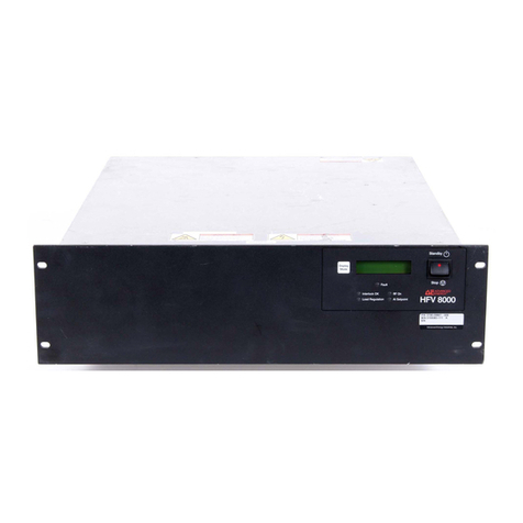
Advanced Energy RFG 5500 User manual

THE ADVANCED ENERGY
RFG 5500 GENERATOR
WITH DISPLAY
User Manual
PN: 5706045-C
December 2000

THE
ADVANCED ENERGY®
RFG 5500 GENERATOR
WITH DISPLAY
User Manual
ADVANCED ENERGY
INDUSTRIES, INC.
1625 Sharp Point Drive
Fort Collins, Colorado 80525
(970) 221-4670
PN: 5706045-C
December 2000

® 2000, Advanced Energy Industries, Inc.
All rights reserved. Printed in the United States of America. This
manual instructs the reader on how to safely install and operate the
equipment described herein. Making copies of any part of this manual
for any purpose without permission is a violation of U.S. copyright law.
In the interest of providing even better equipment, Advanced Energy
Industries, Inc., reserves the right to make product changes without
notification or obligation. To the best of our knowledge, the
information contained in this manual is the most accurate available as
of the date on the title page.
For more information write Advanced Energy Industries, Inc., 1625
Sharp Point Drive, Fort Collins, CO 80525.

WA R N IN G
SAFE OPERATING PROCEDURES AND PROPER USE OF THE
EQUIPMENT ARE THE RESPONSIBILITY OF THE USER OF
THIS SYSTEM.
Advanced Energy Industries, Inc., provides information on its products and
associated hazards, but it assumes no responsibility for the after-sale
operation of the equipment or the safety practices of the owner or user.
This equipment produces or uses potentially lethal high-voltage, high-
current, radio frequency (RF) energy. You should read this manual and
understand its contents before you attempt to hook up or operate the
equipment it describes. Follow all safety precautions. NEVER DEFEAT
INTERLOCKS OR GROUNDS.
DANGER! All personnel who work with or who are exposed to this
equipment must take precautions to protect themselves against serious or
possibly fatal bodily injury.
DO NOT BE CARELESS AROUND THIS EQUIPMENT.


P/N 5706045C December 2000 TOC-1
RFG 5500 GENERATOR WITH DISPLAY
Contents
Introduction. . . . . . . . . . . . . . . . . . . . . . . . . . . . . . . . . . . . . . . . . . . . .I-1
Read This Page . . . . . . . . . . . . . . . . . . . . . . . . . . . . . . . . . . . . . . .I-1
Overview of the Manual . . . . . . . . . . . . . . . . . . . . . . . . . . . . . . . .I-1
Interpreting the Manual . . . . . . . . . . . . . . . . . . . . . . . . . . . . . . . .I-1
Type Conventions . . . . . . . . . . . . . . . . . . . . . . . . . . . . . . . . . .I-1
Symbols . . . . . . . . . . . . . . . . . . . . . . . . . . . . . . . . . . . . . . . . . I-2
Safety . . . . . . . . . . . . . . . . . . . . . . . . . . . . . . . . . . . . . . . . . . . . . .I-3
Regulatory Requirements . . . . . . . . . . . . . . . . . . . . . . . . . . . . . . .I-3
Specifications . . . . . . . . . . . . . . . . . . . . . . . . . . . . . . . . . . . . . . . . . . 1-1
General Description . . . . . . . . . . . . . . . . . . . . . . . . . . . . . . . . . . 1-1
Physical Specifications . . . . . . . . . . . . . . . . . . . . . . . . . . . . . . . . 1-2
Electrical Specifications . . . . . . . . . . . . . . . . . . . . . . . . . . . . . . . 1-2
Environmental Specifications . . . . . . . . . . . . . . . . . . . . . . . . . . . 1-4
Connectors, controls, and Indicators. . . . . . . . . . . . . . . . . . . . . . . . . 2-1
Interface Configurations . . . . . . . . . . . . . . . . . . . . . . . . . . . . . . . 2-1
User Port . . . . . . . . . . . . . . . . . . . . . . . . . . . . . . . . . . . . . . . . 2-1
User Port Electrical Characteristics . . . . . . . . . . . . . . . . . . . 2-2
Operator Panel Functions . . . . . . . . . . . . . . . . . . . . . . . . . . . . . . 2-5
Front Panel . . . . . . . . . . . . . . . . . . . . . . . . . . . . . . . . . . . . . . 2-6
Rear Panel . . . . . . . . . . . . . . . . . . . . . . . . . . . . . . . . . . . . . . . 2-7
Installation and Setup . . . . . . . . . . . . . . . . . . . . . . . . . . . . . . . . . . . . 3-1
Setting Up . . . . . . . . . . . . . . . . . . . . . . . . . . . . . . . . . . . . . . . . . . 3-1
Unpacking. . . . . . . . . . . . . . . . . . . . . . . . . . . . . . . . . . . . . . . 3-1
Grounding . . . . . . . . . . . . . . . . . . . . . . . . . . . . . . . . . . . . . . . 3-1
Mounting. . . . . . . . . . . . . . . . . . . . . . . . . . . . . . . . . . . . . . . . 3-1
Mounting Hole Locations and Dimensions . . . . . . . . . . . . . 3-2
Connecting Cooling Water . . . . . . . . . . . . . . . . . . . . . . . . . . . . . 3-3
Connecting Input Power . . . . . . . . . . . . . . . . . . . . . . . . . . . . . . . 3-3
Connecting Output Power. . . . . . . . . . . . . . . . . . . . . . . . . . . . . . 3-3
Output Power Cable Recommendations . . . . . . . . . . . . . . . . 3-3
Connecting User Port . . . . . . . . . . . . . . . . . . . . . . . . . . . . . . . . . 3-4
Interface Cabling Requirements . . . . . . . . . . . . . . . . . . . . . . 3-4
Operation . . . . . . . . . . . . . . . . . . . . . . . . . . . . . . . . . . . . . . . . . . . . . 4-1

TOC-2 December 2000 P/N 5706045C
ADVANCED ENERGY
First-Time Operation. . . . . . . . . . . . . . . . . . . . . . . . . . . . . . . . . . 4-1
Troubleshooting . . . . . . . . . . . . . . . . . . . . . . . . . . . . . . . . . . . . . . . . 5-1
Check First . . . . . . . . . . . . . . . . . . . . . . . . . . . . . . . . . . . . . . . . . 5-1
Power Off . . . . . . . . . . . . . . . . . . . . . . . . . . . . . . . . . . . . . . . 5-1
Power On . . . . . . . . . . . . . . . . . . . . . . . . . . . . . . . . . . . . . . . 5-1
Troubleshooting Flowchart . . . . . . . . . . . . . . . . . . . . . . . . . . . . . 5-1
Other Technical Problems. . . . . . . . . . . . . . . . . . . . . . . . . . . . . . 5-5
Returning Units for Repair . . . . . . . . . . . . . . . . . . . . . . . . . . . . . 5-5
Warranty
Index

P/N 5706045C December 2000 I-1
RFG 5500 GENERATOR WITH DISPLAY
INTRODUCTION
CONTENTS
Read This Page . . . . . . . . . . . . . . . . . . . . . . . . . . . . . . . . . . . . . . . . . . . . .I-1
Overview of the Manual . . . . . . . . . . . . . . . . . . . . . . . . . . . . . . . . . . . . . .I-1
Interpreting the Manual . . . . . . . . . . . . . . . . . . . . . . . . . . . . . . . . . . . . . .I-1
Safety . . . . . . . . . . . . . . . . . . . . . . . . . . . . . . . . . . . . . . . . . . . . . . . . . . . .I-3
Regulatory Requirements . . . . . . . . . . . . . . . . . . . . . . . . . . . . . . . . . . . . .I-3
READ THIS PAGE!
We know that some of you want to start the generator now and that you don’t feel you
have the time to read the entire manual. Following are sub-sections you need to read in
order to get started. Overview of the Manual and Interpreting the Manual are short
sections intended to guide you through the manual.
Overview of the Manual explains the organization of the manual, so you can more
quickly find what you need. Interpreting the Manual explains the type conventions
(what it means when a word appears in capitalized italic type, for instance), and what
the icons (symbols) mean.
OVERVIEW OF THE MANUAL
The main table of contents is an outline of the major topics covered in the manual. It
contains only the chapter titles and the first heading levels within each chapter, so you
can skim it and get an idea of what is contained, without being overwhelmed by
several heading levels.
When you turn to a chapter, a table of contents lists each sub-heading in the chapter
and its page number.
INTERPRETING THE MANUAL
Type Conventions
To help you quickly pick out what is being discussed, the manual presents certain
words and phrases in type that are different from the rest of the text.

I-2 December 2000 P/N 5706045C
ADVANCED ENERGY
Pin and signal names appear in capitalized italics (RF PWR ON CMD.D). Labels that
are on the unit (switches, indicators, etc.) generally appear in boldface capital letters
(MODIFY). Exceptions are port names, which simply begin with a capital letter (User
port).
Functions are printed in boldface lowercase letters (analog input filtering).
Symbols
This symbol represents important notes concerning potential harm to
people, this unit, or associated equipment. It is found whenever needed in
the manual.
The following symbols may appear on your unit.
Short circuit protected
Dangerous voltage
Chassis (EMI) ground
Non-Ionizing elecstromagnetic radiation
General Danger (Refer to Manual)

P/N 5706045C December 2000 I-3
RFG 5500 GENERATOR WITH DISPLAY
SAFETY
Do not attempt to install or operate this equipment without having proper training first.
Make sure this unit is properly grounded. (Protective ground is accomplished through
the green/yellow ground wire in the ac power cord. RF (EMI) grounding is
accomplished by using a copper strap between earth ground and the ground stud on the
unit’s chassis
Ensure all cables are connected and are tight. NOTE: Low voltage control cabling
must be routed away from all ac and RF cables.
Verify that input line voltage and current capacity are correct before powering the
generator.
Use proper ESD precautions.
DO NOT BE CARELESS AROUND THIS EQUIPMENT.
REGULATORY REQUIREMENTS
This device has been tested and complies with safety standards DIN VDE 0160, DIN
VDE 0160 A1, prEN 50178, EMC standard(s) EN 50081-2 (Class A, Group 2),
EN 50082-2, and FCC Part 18. This device must be installed and used only in
compliance with the standards listed, VDE 0113, EN 60204, and applicable
requirements.

I-4 December 2000 P/N 5706045C
ADVANCED ENERGY

P/N 5706045C December 2000 1-1
RFG 5500 GENERATOR WITH DISPLAY
SPECIFICATIONS
CONTENTS
General Description . . . . . . . . . . . . . . . . . . . . . . . . . . . . . . . . . . . . . . . . 1-1
Physical Specifications . . . . . . . . . . . . . . . . . . . . . . . . . . . . . . . . . . . . . . 1-2
Electrical Specifications . . . . . . . . . . . . . . . . . . . . . . . . . . . . . . . . . . . . . 1-2
Environmental Specifications . . . . . . . . . . . . . . . . . . . . . . . . . . . . . . . . . 1-4
GENERAL DESCRIPTION
The RFG 5500 is a 13.56 MHz RF generator designed to regulate its output power based on
forward power. The RFG 5500 provides up to 5000 W into a 50 Ω, non-reactive load. The
RFG 5500 includes a clamp circuit to guarantee that the RF output is less than 1 W if the
requested setpoint is zero.
The unit is controlled through a 15-pin analog/digital user port. There is no operator control
panel provided on this unit. A numeric display and eight status LEDs are visible from the front
of the unit for monitoring the generator functions.
The RFG 5500 is designed for 19”rack mounting with a panel height of 7”. AC power for the
RFG 5500 is supplied from a 4-wire, 3 φwith ground, 208 V ac (nominal) power source. No
neutral connection is required. The unit is water cooled with no provisions or requirements for
forced air cooling.
The RFG 5500 provides a system interlock connection through its 15-pin User port interface.
A contact resistance of 1.2 KΩor less between the interlock pin (11) and chassis ground
enables the unit.
The RFG 5500 protects itself from damage under the following conditions:
•Any internal overcurrent condition not directly related to the output load condition as
protected by current limiting or fuse.
•Excessive internal temperature (may be caused by lack of proper cooling water flow,
excessive ambient operating temperature, or other causes).
•Any combination of input AC line phase drop out.
•Input line brown out (under voltage) or over voltage.

1-2 December 2000 P/N 5706045C
ADVANCED ENERGY
PHYSICAL SPECIFICATIONS
Size 17.8 cm (H) x 48.3 cm (W) x 58.4 cm (D) (7”(H) x
19”(W) x 23”(D))
Weight 52.2 Kg (115 pounds) maximum
Mounting Rack mounting ears provided for standard 19”
instrumentation rack. Side handles are provided to
assist in lifting.
Clearance Clearance of 4”at rear of panel required for
interconnects. No additional clearance about unit for
ambient air flow is required.
Connector/Cable Specifications
RF Output Connector Type LC Female
AC Power Input 4.6 m (15’), 4-wire cord (SO, 8/4, 90C type, or
equivalent) with Hubbell CS8365C connector.
Circuit Breaker Lockout A bracket for holding the breaker handle in the on or
off position is included.
User Port Connector 15-pin, subminiature-D, female
Coolant Connectors 0. 5”female NPT
RF Grounding Connector ¼-20 ground stud located on the rear of the unit
ELECTRICAL SPECIFICATIONS
Input Power Specifications
Line Voltage 187 to 229 V ac (nominal 208 V); 3 φ
Line Frequency 50 to 60 Hz
Line Current 23 A/φtypical at 5 kW
Line Power 8300 W at full rated RF output power (AC to RF
efficiency, 60%).
Overcurrent Protection 40 A circuit breaker
RF Output Specifications
Frequency 13.56 MHz ±0.005%
Full Rated Output Power 5000 W forward power minimum into a 50 Ωnon-
reactive load
Output Power Range 100 to 5000 W. RF output is less than 1 W if the
requested setpoint is 0.
Output Impedance 50 Ωfor maximum power transfer. (See Figure 1-1 for
power derating into non-50 Ωloads.)

P/N 5706045C December 2000 1-3
RFG 5500 GENERATOR WITH DISPLAY
Regulation Forward power regulated at 1% of setpoint or ±5 W
(whichever is greater) into a 50 Ωload
Response Time < 40 ms rise and fall time from RF on or RF off
Warm-Up Time Delay Approximately 500 ms from AC On to RF On
Reflected Power Automatic foldback (forward power limiting) occurs if
the reflected power at the generator output exceeds
1000 W. The generator is capable of generating 850 W
of reflected power into an open circuit.
Harmonics At full rated output, all harmonics are -55 dBc (below
the RF output signal) when operated into a 50 Ω, non-
reactive load.
Spurious Signals Non-harmonic spurious and noise signals are -50 dBc
(below the RF output signal) when operated into a
50 Ω, non-reactive load.
Transient Response Less than 0.1% change in output power for a 10%
change in the ac line voltage
Command Power Repeatability < 0.5% over time for same generator, ±1% generator
to generator
Demonstrated Open Loop Power 10 kW into a 50 Ωload
Power Margin 100%
FIGURE 1-1. Output Power Derating Curve
RFG 5500 (5kW Scaling) Power Derating
VoltageStandingWaveRatio(VSWR)
Power - Watts
0
1000
2000
3000
4000
5000
11.522.533.544.55
ForwardPower
ReflectedPower

1-4 December 2000 P/N 5706045C
ADVANCED ENERGY
ENVIRONMENTAL SPECIFICATIONS
Ambient Temperature
Operating 5°C to +40°C (+41°F to +104°F)
Storage -25°C to +55°C (-13°F to +131°F)
Transportation -25°C to +55°C (-13°F to +131°F)
Humidity 15 to 85% relative humidity; non-condensing
Atmospheric Pressure
Operating ≥745 mbar (≤2500 m (8,203’) equivalent altitude)
Storage ≥585 mbar (≤4000 m (13,124’) equivalent altitude)
Transportation ≥480 mbar (≤5000 m (16,405’) equivalent altitude)
Coolant Requirements
Heat Removal 11,270 BTU/hr (3300 W) at full rated RF output power
Temperature +5°C to +25°C (+41°F to +77°F) inlet temperature
Flow Rate 15.1 liters (4 gallons) per minute minimum
Pressure 100 psi (6.9 bars) maximum inlet pressure
Contaminates The following specifications are recommended for the
water used to cool the RFG 5500:
•pH between 7 and 9
•total chlorine < 20 ppm
•total nitrate < 10 ppm
•total sulfate < 100 ppm
•total dissolved solids < 250 ppm
•total hardness expressed as calcium carbonate
equivalent less than 250 ppm
•specific resistivity of 2500 Ωper centimeter or
higher at 25°C
•total dissolved solids (TDS) as estimated by the
following:
TDS ≤640,000
specific resistivity (in Ω/cm)

P/N 5706045C December 2000 2-1
RFG 5500 GENERATOR WITH DISPLAY
CONNECTORS, CONTROLS, AND INDICATORS
CONTENTS
Interface Configurations. . . . . . . . . . . . . . . . . . . . . . . . . . . . . . . . . . . . . . . . . . . 2-1
Operator Panel Functions . . . . . . . . . . . . . . . . . . . . . . . . . . . . . . . . . . . . . . . . . . 2-5
Front Panel . . . . . . . . . . . . . . . . . . . . . . . . . . . . . . . . . . . . . . . . . . . . . . . . . . . . . 2-6
Rear Panel. . . . . . . . . . . . . . . . . . . . . . . . . . . . . . . . . . . . . . . . . . . . . . . . . . . . . . 2-7
INTERFACE CONFIGURATIONS
The following table provides the connector pinouts for the User port connector on the
RFG 5500.
User Port
Connector type: 15-pin, subminiature-D, shielded, female
FIGURE 2-1 User Port Connector
Pin Name Description
1 SETPOINT STATUS DIGITAL OUTPUT—A logic high level (+5 V)
indicates that an internal power limit has been
encountered. When RF power is enabled, a low level
(0 V) indicates that the generator is “at setpoint.”
2 REFL PWR MONITOR ANALOG OUTPUT—This signal represents the
reflected power as measured at the output of the
generator. This signal is scaled at 1 kW per V. The
maximum reflected power is 1 kW.
3 FWD PWR MONITOR ANALOG OUTPUT—This signal represents the forward

2-2 December 2000 P/N 5706045C
ADVANCED ENERGY
power as measured at the output of the generator. This
signal is scaled at 1 kW per V.
4 RF PWR ON DIGITAL INPUT—This signal is used to activate the RF
output of the generator. A voltage level of 4 V to 30 V on
pin 4 enables the RF power. If pin 4 is open or
grounded, RF power is inhibited.
5 SETPOINT ANALOG INPUT—This 0 to 10 V signal defines the
desired setpoint for the generator’s RF output and is
scaled to represent 0 to 5000 W.
6 GROUND GROUND REFERENCE—This pin is referenced to the
signal/chassis ground in the generator.
7 RF ON STATUS DIGITAL OUTPUT—A logic high level (+5 V)
indicates that the RF power is present at the output of the
generator. A logic low level indicates that RF power is
inhibited. The interlock loop must be closed and the RF
PWR ON signal must be active to enable RF power.
8 EXTERNAL BIAS REFERENCE VOLTAGE—This pin is tied to the
generator’s +15 Vdc through a 5.62 kΩresistor. The
intended use of this pin is for notifying the user that ac
power is enabled within the generator.
9 RF ON BIAS REFERENCE VOLTAGE—This pin is tied to the
generator’s +15 Vdc through a 1.21 kΩresistor. The
intended use of this pin is to enable RF power by
externally junpering it to pin 4.
10 Reserved Reserved for future use
11 INTERLOCK INTERLOCK—This pin is part of a series interlock
string which must be satisfied to enable ac power in the
generator. Pin 11 must be grounded to enable RF power
(a contact resistance of 1.2 kΩor less to ground will
satisfy the interlock criteria).
12 Reserved Reserved for future use
13 Reserved Reserved for future use
14 Reserved Reserved for future use
15 Reserved Reserved for future use
User Port Electrical Characteristics
The User port on the RFG 5500 provides analog and digital signals for control and
monitoring of the generator functions. Figure 2-2 shows the electrical diagrams for

P/N 5706045C December 2000 2-3
RFG 5500 GENERATOR WITH DISPLAY
the interface circuitry in the generator. The following are descriptions of the signal
types used in the RFG 5500 .
Analog Outputs The analog readback signals from the generator
(pins 2 and 3) are driven by precision, low-offset
operational amplifiers (industry type OP200GP).
These devices are capable of driving high-
capacitance loads such as those expected in shielded
interface applications. The user’s receiver must
present a 10 kΩ(or greater) impedance to these
signals. The readback signals, which represent the
forward and reflected power as measured at the
output of the generator, are scaled to 1 V per kW.
Analog Input The setpoint signal from the user (pin 5) is a 0 to 10
volt signal scaled to represent the desired forward
power from the generator (refer to the signal
description table for details). The driver circuit must
be capable of operating into a high capacitance load
condition (cable capacitance plus 1000 pF at the
EMI filter in the generator).
Digital Outputs The status signals provided by the generator (pins 1
and 7) are opto-coupled with NPN transistor outputs
(industry type 4N37). The emitter of each transistor
is biased to ground with a 2 kΩresistor. The
collector of each transistor is tied to +5.1 V in the
generator. Each transistor can provide a minimum
of 8 mA of collector current and may be operated
with a collector-to-emitter voltage of up to 30 V.
Refer to the attached signal description table for
signal definitions.
Digital Input The RF PWR ON control signal (pin 4) is opto-
coupled (industry type 4N37). The user’s signal
drives the LED in the opto-coupler through a 1 kΩ
resistor. A signal level of 4 V to 30 V applied to
pin 4 enables the RF power.
Interlock The interlock signal (pin 11) is opto-coupled
(industry type MOC207). The anode of the LED in
the opto-coupler is tied to +15 V in the generator
through a 475 Ωresistor. The user’s signal is tied to
the cathode. Grounding pin 11 (contact resistance
of less than 1.2 kΩohms) energizes the contactor
that enables ac power within the generator.

2-4 December 2000 P/N 5706045C
ADVANCED ENERGY
FIGURE 2-2 User Port Electrical Diagrams

P/N 5706045C December 2000 2-5
RFG 5500 GENERATOR WITH DISPLAY
OPERATOR PANEL FUNCTIONS
A numeric display and eight status LEDs are provided on the front of the unit for
monitoring the basic generator functions.
DISPLAY 3-digit numeric display (seven-segment) used to
display one of three selected generator functions
(see definition of the DISPLAY SELECT switch
below).
DISPLAY SELECT This momentary push button switch is used to select
the desired parameter for display (subsequent
depressions of the switch cycle through the three
selections). There are three LEDs adjacent to the
switch for indicating the currently selected display
mode. The displayable parameters are:
•Setpoint
•Fwd/Load Pwr
•Refl Pwr
INDICATORS:
AC ON This LED indicates that ac power is available within
the unit, all three phases are present, the main contactor
is energized, the ac voltage to the inverter section is
within the allowable voltage range, and all interlock
criteria are satisfied. When this indicator is lit, the unit
is ready to supply RF output power.
RF ON This LED indicates that RF power is on (enabled).
Depending on the selected setpoint value, RF power
may or may not be present at the output connector.
ALARM This LED indicates that the unit is unable to satisfy the
requested setpoint power due to some limit or alarm
condition in the generator. The conditions that can
cause an alarm are high VSWR, over-temperature, and
internal power limits. In the event of an over-
temperature condition, the RF On command or ac
circuit breaker must be toggled to reset the over-
temperature fault.
Watts This LED indicates that the value being displayed is in
watts. For the RFG 5500, this indicator is always lit.
X 1000 This LED indicates that the value being displayed has
been scaled and must be multiplied by 1000. For the
RFG 5500, this indicator is always lit.
Table of contents
Other Advanced Energy Portable Generator manuals
Popular Portable Generator manuals by other brands
Rothenberger Industrial
Rothenberger Industrial ROTURBO 12000 Instructions for use
Infinite
Infinite TRANSTECTOR 700 AV/T Series owner's manual
NORTH AMERICAN TOOLS
NORTH AMERICAN TOOLS 650 Operation manual

Colorado Video
Colorado Video 619HWY instruction manual

WARRIOR
WARRIOR EV 30i Manual guide
EWM
EWM Titan XQ 350 puls D operating instructions

