manuals.online logo
Brands
  1. Home
  2. •
  3. Brands
  4. •
  5. Advanced Instruments
  6. •
  7. Measuring Instrument
  8. •
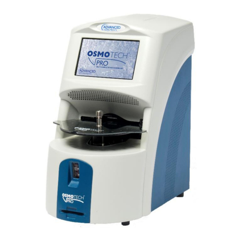
  9. Advanced Instruments OsmoTECH PRO User manual

Advanced Instruments OsmoTECH PRO User manual

Hot-Line Technical Service: Advanced Instruments and worldwide distributor network provides 24/7
comprehensive customer service and technical support.
©2019 Advanced Instruments. Alltrademarks are the property of their respective companies.
Two Technology Way / 781-320-9000
Norwood, Massachusetts 02062, USA
800-225-4034 Fax:781-320-8181
aicompanies.com
222123PM Rev 0
Replacement Procedure 222123PM
OsmoTECH®PRO Block Probe
Scope
This document describes how to replace the block
probe (p/n 222123R) on the OsmoTECH® PRO
Multi‑Sample Micro‑Osmometer. It is intended for use in
conjunction with service procedures that require access
to the OsmoTECH PRO interior.
Tools required
• #1 and #2 Phillips screwdrivers
• 5/16” nut driver
• 7/64” and 9/64” Allen wrenches
• 30 µL sample tube
• Static grounding wrist strap
Parts and materials required
Replacement part 222123R
Related documents
• OsmoTECH PRO Disassembly and Reassembly
(p/n 222202PM)
• OsmoTECH PRO Service Guide (p/n 222006EN)
Safety notices
WARNING: Hazardous Voltage. Power cord must
be disconnected to prevent electrical shock.
NOTICE: Internal components may be damaged
by static electricity. A static grounding wrist
strap must be worn during this procedure.
NOTICE: Improper connections may cause
damage to the instrument.
Disconnecting the control PCB
1. Remove the rear and side enclosure as explained in
OsmoTECH PRO Disassembly and Reassembly.
2. Remove the cable clamp [A] that secures the C10
sample probe cable and the C11 block probe cable
to the side of the power supply and controls
assembly.
A
3. Unplug the C10 and C11 connectors from the control
PCB.
4. Disconnect the B1, B2, B3, B4, B6, B7, B8, B9, and
B10 connectors on the motor/sensor cable harness
from their mating connectors.
5. Disconnect the A1, A2, A3, and A4 connectors on
the cooling system harness from their mating
connectors.
Replacement Procedure
OsmoTECH® PRO Block Probe
Page 2 222123PM Rev 0
Removing the power supply and controls
assembly
1. Rest the instrument on its back side.
2. Remove the two screws [B] that secure the power
supply and controls assembly to the bottom of the
chassis.
B
3. Place the instrument in the upright position.
4. Remove the two screws [C] that secure the power
supply and controls assembly to the rear of the
chassis.
C
5. Slide the power supply and controls assembly out of
the base assembly.
Removing the osmometer module
1. Remove the four socket head cap screws and
washers [D] that secure the osmometer module
mounting bracket to the chassis.
D
2. Carefully slide the osmometer module out of the
instrument.
3. Remove the hex nut and washer [E] that secures the
SPG and BPG ring terminals to the side of the
osmometer module mounting bracket.
4. Remove the four socket head cap screws and
washers [F] that mount the osmometer module to
the osmometer module mounting bracket (which is
secured to the chassis).
F
F
F
E
5. Lift the osmometer module o of the osmometer
module mounting bracket.
Replacement Procedure
OsmoTECH® PRO Block Probe
Page 3 222123PM Rev 0
Removing the sample cooling assembly
1. Remove the four screws and washers [F] that
secure the cooling fan, the finger guard, and the
air‑flow diverter to the cooling assembly’s heatsink.
FF
Do not remove the cooling fan wire leads from the
cable clamps.
NOTE: Remember/record the position and
orientation of the cooling fan before
removing it from the chassis.
2. Disconnect the sample well drain tubing [G] from
the drain tube [H].
H
G
3. Remove the four socket head cap screws and
washers [I] that are used to secure the sample
cooling assembly to the sample well mounting
block.
II
One of the socket head cap screws also secures a
cable clip.
4. Remove the block probe cable, the thermo‑electric
cable, and the solenoid cable from the two cable
clamps [J].
J
J
5. Detach the cable clip [K] from the thermo‑electric
wire leads.
K
6. Carefully lift the sample cooling assembly out of the
osmometer module assembly.
Replacement Procedure
OsmoTECH® PRO Block Probe
Page 4 222123PM Rev 0
Removing the block probe
1. Remember/record:
• the position of the block probe cable and gently
remove it from the sample cooling assembly.
• how far that the block probe is inserted into the
sample cooling assembly.
2. Fill the syringe with thermal grease and insert the
syringe tip all the way into the block probe hole [M].
3. Inject grease to fill the hole while slowly
withdrawing the tip to prevent air pockets from
forming.
L
4. Record the four‑digit resistance value [M] listed on
the block probe cable.
Replacing the block probe
1. From the main menu, press SETTINGS > PROBE
RESISTANCE
2. Log in to your account.
3. Enter the resistance value [M] listed on the block
probe cable.
M
4. Recalibrate the instrument.
5. To avoid damaging the probe and to make sure that
thermal grease is properly displaced, slowly insert
the replacement block probe cable into the block
probe hole.
6. Once the block probe cable is fully inserted, hold it
in place until excess thermal grease stops oozing
out of the hole
7. Wipe away any residual grease.
Once all excess thermal grease has been removed
from the block probe hole, the cable can remain in
place by itself.
Replacing the sample cooling assembly
Refer to Removing the sample cooling assembly for
images and callouts.
1. Loosely secure the sample cooling assembly and
the cable clip to the sample well mounting block
using the four socket head cap screws and washers
[I].
The heatsink should be flush with the sample well
mounting block’s uprights. Make sure that the cable
clip is positioned as shown in [K].
Place a sample tube [N] into the sample cooling
assembly.
N
2. Lift up the sample well mounting block until the
sample tube is just below the stripper bracket.
3. Carefully lower the movable plate that secures the
sample probe until the probe enters the sample
tube.
NOTE: Make sure that the sample cooling assembly
aligns with the sample probe. When aligning,
do not move either part more than necessary
to avoid damaging the sample probe.
Replacement Procedure
OsmoTECH® PRO Block Probe
Page 5 222123PM Rev 0
4. Tighten the four socket head cap screws [I] to
secure the sample cooling assembly and the cable
clip.
5. Lift up the movable plate that secures the sample
probe, and lower the sample well mounting block.
6. Remove the sample tube from the sample cooling
assembly.
7. Secure the thermo‑electric wire leads with the cable
clip [K].
8. Secure the block probe cable, the thermo‑electric
cable, and the solenoid cable wire leads using the
two cable clamps [J].
Make sure that there is a service loop [O] between
the two cable clamps.
O
9. Reconnect the sample well drain tube [G] from the
fitting located on the drain tube adapter [H].
10. Secure the cooling fan, the finger guard, and the
air‑flow diverter to the cooling assembly’s heatsink
using the four screws and washers.
Make sure that the air‑flow diverter [P] is equally
spaced on the heatsink.
P
Replacing the osmometer module
Refer to Removing the osmometer module for images
and callouts.
1. Mount the replacement osmometer module to the
osmometer module mounting bracket using the four
socket head cap screws and washers [F].
2. Secure the SPG and BPG ring terminals to the side
of the osmometer module mounting bracket using
the hex nut and washer [E].
3. Slide the osmometer module into the instrument.
4. Mount the osmometer module mounting bracket to
the chassis using the four socket head cap screws
and washers [D].
Reconnecting the control PCB
Refer to Disconnecting the control PCB for images and
callouts.
1. Place the instrument in an upright position.
2. Plug the A1, A2, A3, and A4 connectors on the
cooling system harness into their mating connectors.
3. Plug the B1, B2, B3, B4, B6, B7, B8, B9, and B10
connectors on the motor/sensor cable harness into
their mating connectors.
4. Plug the C10 and C11 connectors into the control PCB.
5. Secure the C10 sample probe cable and the C11
block probe cable to the side of the power supply
and controls assembly with the cable clamp and
screw [A].
6. Reassemble the instrument by performing the
reassembly instructions in OsmoTECH PRO
Disassembly and Reassembly.
7. When the instrument powers up, press SETTINGS >
PROBE RESISTANCE from the main menu.
8. Change the block probe resistance value to match
the value previously recorded.
9. Calibrate the instrument (see Calibration in the
service guide).

Other manuals for OsmoTECH PRO

3

Other Advanced Instruments Measuring Instrument manuals
Advanced Instruments 3250 User manual

Advanced Instruments

Advanced Instruments 3250 User manual

Advanced Instruments AE Series User manual

Advanced Instruments

Advanced Instruments AE Series User manual

Advanced Instruments GPR-IN190 User manual

Advanced Instruments

Advanced Instruments GPR-IN190 User manual

Advanced Instruments A2O User manual

Advanced Instruments

Advanced Instruments A2O User manual

Advanced Instruments GPR-1800 AIS LD User manual

Advanced Instruments

Advanced Instruments GPR-1800 AIS LD User manual

Advanced Instruments OsmoTECH PRO Setup guide

Advanced Instruments

Advanced Instruments OsmoTECH PRO Setup guide

Advanced Instruments OsmoTECH Setup guide

Advanced Instruments

Advanced Instruments OsmoTECH Setup guide

Advanced Instruments OsmoPRO User manual

Advanced Instruments

Advanced Instruments OsmoPRO User manual

Advanced Instruments 4C3 User manual

Advanced Instruments

Advanced Instruments 4C3 User manual

Advanced Instruments 3300 User manual

Advanced Instruments

Advanced Instruments 3300 User manual

Advanced Instruments OsmoPRO User manual

Advanced Instruments

Advanced Instruments OsmoPRO User manual

Advanced Instruments GPR-1200 User manual

Advanced Instruments

Advanced Instruments GPR-1200 User manual

Advanced Instruments 3300 User manual

Advanced Instruments

Advanced Instruments 3300 User manual

Advanced Instruments 3320 User manual

Advanced Instruments

Advanced Instruments 3320 User manual

Advanced Instruments 3250 User manual

Advanced Instruments

Advanced Instruments 3250 User manual

Advanced Instruments GPR-2500 User manual
Advanced Instruments

Advanced Instruments GPR-2500 User manual

Popular Measuring Instrument manuals by other brands
Isotech 988 quick start guide

Isotech

Isotech 988 quick start guide

B+K precision 5332 Analyst 2050 instruction manual

B+K precision

B+K precision 5332 Analyst 2050 instruction manual

Ono Sokki HT-6200 instruction manual

Ono Sokki

Ono Sokki HT-6200 instruction manual

Pro's Kit MT-4617LED user manual

Pro's Kit

Pro's Kit MT-4617LED user manual

Aqualytic CHECKIT Comparator instruction manual

Aqualytic

Aqualytic CHECKIT Comparator instruction manual

B meters MAG instruction manual

B meters

B meters MAG instruction manual

Electronics International Inc FP-5L operating instructions

Electronics International Inc

Electronics International Inc FP-5L operating instructions

HIK VISION DS-8108LHFHI-K2 quick start guide

HIK VISION

HIK VISION DS-8108LHFHI-K2 quick start guide

Dream Catcher ME3100 quick start guide

Dream Catcher

Dream Catcher ME3100 quick start guide

i-PRO WJ-NX310K Series Important information

i-PRO

i-PRO WJ-NX310K Series Important information

PerkinElmer DSC 4000 Installation and hardware guide

PerkinElmer

PerkinElmer DSC 4000 Installation and hardware guide

HANYOUNG NUX HL Series instruction manual

HANYOUNG NUX

HANYOUNG NUX HL Series instruction manual

Heal-Tech GIpro DS Series Installation and operation manual

Heal-Tech

Heal-Tech GIpro DS Series Installation and operation manual

Promax CP-543C instruction manual

Promax

Promax CP-543C instruction manual

Black Box FOLTIB manual

Black Box

Black Box FOLTIB manual

oneConcept 10029831 manual

oneConcept

oneConcept 10029831 manual

Promax PROMAX-10 manual

Promax

Promax PROMAX-10 manual

Bio-Tek PowerWave Operator's manual

Bio-Tek

Bio-Tek PowerWave Operator's manual

manuals.online logo
manuals.online logoBrands
  • About & Mission
  • Contact us
  • Privacy Policy
  • Terms and Conditions

Copyright 2025 Manuals.Online. All Rights Reserved.