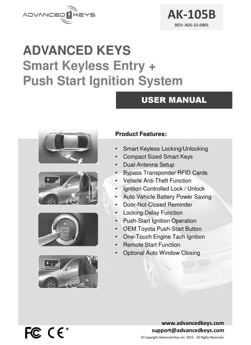
Advanced Keys AK-PSB06 User manual

ADVAN CED KEYS
Push-Start Ignition System
INSTALLATION GUIDE
AK-PSB06
REV: A06-13-0901
www.advancedkeys.com
support@advancedkeys.com
© Copyright Advanced Keys Inc. 2013. All Rights Reserved.
*
Product Features:
•Push-Start Ignition Operation
•OEM Toyota Push-Start Button
•One-Touch Engine Tach Ignition
•Backup Ignition Relays
•Diesel Wait-to-Start Input
•Immobilizer Bypass Enable Trigger
•Remote Start Function with AK-103
•Compatible with Aftermarket Alarms
•Compatible with OEM Vehicle Setup

2© Copyright Advanced Keys Inc. 2013. All Rights Reserved.
Table Of Contents ....................................................................................... 2
Product Contents ........................................................................................ 2
Warning and SafetyInformation .................................................................3
SafetyPrecautions ................................................................................... 3
Pre-installation Considerations ................................................................. 3
Connections ................................................................................................. 4
Main Harness Wire Descriptions .............................................................. 4
Access HarnessWire Descriptions ..........................................................5
Controller Wiring Diagram ........................................................................6
Installation.....................................................................................................7
Installation Overview ................................................................................ 7
Installation Note ....................................................................................... 7
Tach Ignition Programming .......................................................................8
Ignition Test and Troubleshooting ............................................................ 9
Remote Start Function ............................................................................. 10
Steering Column Lock Bypass ..................................................................11
Ignition Wiring Diagram............................................................................11
Keysense Function Bypass (Optional) ...................................................... 12
Push-Start Button Installation ................................................................... 12
Frequently Asked Questions ...................................................................... 13
Closing Up ....................................................................................................15
References Information ............................................................................... 15
Specifications .......................................................................................... 15
Product Registration ................................................................................ 15
Warranty.................................................................................................. 16
FCC And Canadian Compliance .............................................................. 16
TABLE OF CONTENTS
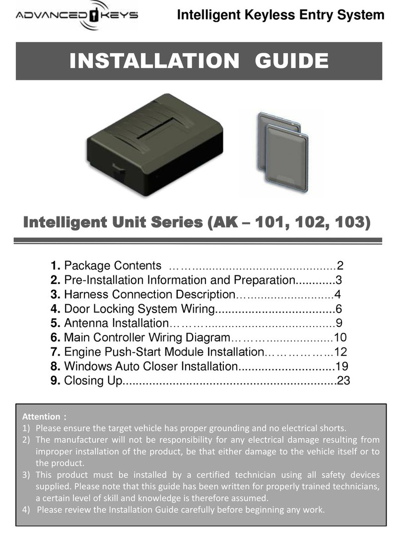
Thefollowing list of components are included in this system:
1 –Push-Start Module
1 –Main / AccessoryHarness
1 –Push-Start Button
PRODUCT CONTENTS
1 –Button Ring Mount
1 –Ignition KeyCover
1 –User Manual/Installation Guide

3
© Copyright Advanced Keys Inc. 2013. All Rights Reserved.
•This product shall be installed by a certified technician therefore a certain level
of competence and knowledge are therefore assumed when reading this guide.
•This guide is provided as a GENERAL installation instructions and vehicle
subjected to installation maybe different.
•This product is designed based onvehicle regulatorystandard.Pleaseobserve
your local public road traffic law and regulations prior to installation.
•Exercise due-diligence when installing this product. The manufacturer and
distributors of this product will not accept anyvehicle damage or personal
injuryresulting from the installation of this product. Installation of this product is
acceptance of this statement and releases the manufacturer/distributors of this
product from anydirect or indirect liabilities.
•Once installation is complete, please returnthis guide along with other
documentations included in this product back to customer for futurereference.
Themanufacturer/distributors of this product does not guarantee this particular
version will be available at a later date.
PRODUCT SAFETYAND LEGALDISCLAIMER
WARNING AND SAFETYINFORMATION
•Carefullyread and understand the User Manual, Installation Guide and
Electrical Service Information for the subjected vehicle before begin work.
•Install in a well-lit, dry,covered areaawayfrom the elements and keep at least
onewindow open all timeduring installation. Do not leavekeyinside ignition
switch and /or detection range. Prepare all tools required for the installation.
Special tools maybe necessarydepending on vehicle.
•Verifythe vehicle has proper grounding and does not have anyoutstanding
electrical/functional issuesprior to installation.
•To avoid short circuit, it is recommended to pull-out related fusesbefore
installation and put them back when installation is complete.
•Only locatenecessarywires related to the installation(most required wiring are
under driver dash/kick panel areas) and connect to the unit according to the
wiring diagram.Use a Multimeter to verifyand confirm wire’s function, polarity
before connecting or disconnecting. We strictlyprohibit testing or modifying
the vehicle’s ECU, airbag and ABS systems.
•Begin function tests on the system after verifying and ensuring all wires have
been connected correctlyand insulated properly.
PRE-INSTALLATION CONSIDERATIONS
DO NOT powerup the module before it is properlygrounded.
Should the unit be powered before being grounded,serious
damage to internal components could occur.
CAUTION

4© Copyright Advanced Keys Inc. 2013. All Rights Reserved.
---
MAIN HARNESS WIRING DESCRIPTIONS
Main Harness 8-Pin 14-16 Gauge
-
Purple
OUTPUT
500mA
Negative START
Connect this output to a data bypass module or vehicle’s Negative(
-
)triggered Starterinput.This output
is rated for 500mA.
DO NOT use this output to drive Starter Motor’s Negative(-) side directly.
White
OUTPUT
30A
Positive START
Connect this output to vehicle’s Starter input at the ignition switch.
IMPORTANT:
Ensurethat theignitioncurrent is not ratedmore than30A. Connect to externalrelay
with
higher current rating if required.
Red INPUT 30A
Battery +12V
Connect to a constant +12V supplywireat the ignitionswitch.Ensurethat theOEM input power wireis
fused for more than30A.
Note:
When no suitable +12V source available, connect to vehicle’s power supply at the fuse junction
boxor connect directlyto the B+ terminal on thebattery.
Blue
OUTPUT
30A
ON 2 / 2nd Ignition Output
If applicable, connect this output wire to vehicle’s secondary ignition (ON 2) input at the ignition
switch.
This output will be +12V in ON and RUN stateand OFFduring Start (crank) State.
Green
OUTPUT
30A
ON 1 / Primary Ignition Output
Connect this output wire to vehicle’s primary ignition (ON) input at the ignition switch.
Black INPUT
Ground
Connected to bare,unpainted metalon chassis. It is recommended to usea factoryground bolt rather
thanaself
-tapping screw. Screws tend to get looseor rusted overtimeand lead to erratic electrical
problems.
Red INPUT 30A
Battery +12V
Connect to a constant +12V supplywireat the ignitionswitch.Ensurethat theOEM input power wireis
fused for more than30A.
Note:
When no suitable +12V source available, connect to vehicle’s power supply at the fuse junction
boxor connect directlyto the B+ terminal on thebattery.
Yellow
OUTPUT
30A
ACC
Connect this output wire to vehicle’s accessory (ACC) input at the ignition switch. This output will be
OFFduring START(crank) state.
+
+
-
+
+
+
+
System State Status LED ACC ON 1 ON 2 START
OFF All Off - - - -
Ready Amber - - - -
ACC Green 12v ---
ON Green (Flashing) 12v 12v 12v -
Step On Brake Amber (Flashing) No Change to Any Output
START (Crank) All Off - 12v -12v
RUN (ON) Backlight Only 12v 12v 12v -
Ignition Outputs State Table:
Following tableshows stateof theignitionoutputswhensystemis inACC, ON, STARTand RUNmode:
OPTIONAL
CONNECTIONS - HARNESS

5
© Copyright Advanced Keys Inc. 2013. All Rights Reserved.
ACCESSORY HARNESS WIRING DESCRIPTIONS
AccessoryHarness 10-Pin 22 Gauge
Orange
OUTPUT
250mA
Bypass Module Control
Thiswireprovidesa constant 250mA positiveoutput whilethesystemis inACC, ON and STARTstates.
Theoutput canbe used to activate externalrelays,
bypassdeviceand bypass(+)type keysenseinput
etc.
Red INPUT
Backup Relay +12v
Pre
-connected to the external backup relays.Thisoutput providesconstant +12v for ON 1 and ON 2
backup relays.
Grey
OUTPUT
500mA
Ground
-When-Running
This output providesa constant 500mA negative output while thesystemis inACC, ON (RUN)and
STARTstates.Thisoutputactivates0.5 seconds beforeACC and it canbe used to activateexternal
relays,
bypassdevicesand bypass (-)type keysenseinput etc.
White INPUT
Neutral Safety Switch
Required for remote start functiononly.Connect this input to a ground source
when vehicle is in
PARKor
NEUTRALgear position.Thiswill prevent the vehicle from remote started whilein a drive gear. See
RemoteStart Function
on page9 for moreinformation on connect and test this input.
IMPORTANT:
PerformNeutralSafetySwitch Testing underthe RemoteStart Functionsectionto verify
switch input
is functional by prevent vehicleremote started in drive gear.
Purple INPUT
Push
-Start Enable
Connect this input to the “Push
-Start Module Control” output on the AK-104 Smart Keymodule.
Note:Depending onJumper Setting (JP2), this input canconnect to a externallyground signalfrom other
device/system to enablethis system.
SeeJumperSetting underInstallationNote for moreinformation.
Pink INPUT
Wait
-to-Start
Optional for remotestart functiononly.Connect to thenegativesideof theGlow Plug Light.Thisinput
will monitorthe Glow Plug Light for Diesel Engine
and it will wait up to 18 seconds untilthe Glow Plug
Light goes out before starting the engine.
Note:this input is not requiredfor non-diesels vehicle.
Brown INPUT
Brake Input
Connect to Brake Switch wire which sees +12V when brake depressed,
grounded or float when
released.
Note:
this input is required for enginestart, stop and programming,thereforeit is essential that it is
proper installed and tested beforestarting this system.
Blue
OUTPUT
250mA ON 2 Backup Relay Control
Pre
-
connected to the external backup ignitionON 2 relays.Thisoutput turnon backup ignitionON 1 relay
when ignition is ON. Connect backup ignition ON 2 relay output to vehicle’s ignition ON 2
input.
Green
OUTPUT
250mA ON 1 Backup Relay Control
Pre
-connected to the external backup ignitionON 1 relays.Thisoutput turnon backup ignitionON 1
relay
when ignition is ON. Connect backup ignition ON 1 relay output to vehicle’s ignition ON input.
Yellow INPUT Engine Tach
Connect this input to a suitable Tach or engineRPM signal sourcewith at least 3 volts (AC) and 20 Hz or
faster signal when engine is at the idle speed. Common Tach reference are: Data bypass module’s Tach
output, negativesideof aninjector,ignition coil or at the EngineControl Module
(ECM).
Note:
this input need not be connected whenjumper(JP1) selects Non-TachIgnition mode. InNon-
Tach
Ignitionmode,engineSTARTor crank timeis depended onhow long thepush
-buttonis held it down.
-
+
+
-
-
-
+
+
+
~
JP2
REQUIRED
JP1
OPTIONAL
OPTIONAL
OPTIONAL
OPTIONAL
REQUIRED
OPTIONAL
OPTIONAL
OPTIONAL
OPTIONAL

Default Settings Optional Settings
Tach Ignition Tachless Ignition
Smart Key Enable Ground Enable
Remote Start Enable* Remote Start Disable*
N/A N/A
6© Copyright Advanced Keys Inc. 2013. All Rights Reserved.
CONNECTIONS - CONTROLLER
PUSH-STARTIGNITION CONTROLMODULEWIRING DIAGRAM
Toyota / Lexus
OEM Push-
Start Button
Purple Negative START
White
Red
Blue
Green
Black
Red
Yellow
Positive START
Battery +12v
(IGNITION 2) ON 2
(IGNITION 1) ON 1
Ground
Battery +12V
ACC
Main Harness
8-Pin 14-16 AWG
30A
30A
Orange
Pink
Purple
Brown
Yellow
Wait-to-Start
Push-Start Enable
Brake
Engine Tach
Ground-When-Running
Black Neutral Safety Switch
Bypass Module Control
Accessory Harness
10-Pin 22 AWG
JP1 JP2 JP3 JP4
+
-
~
Legend:
Input
Output
Positive Type
Negative Type
JP1
JP2
JP3
JP4
Frequency Type
In-Line Fuse
Jumper Settings:
Soldered Wiring
JP2 JP3
JP1
*Remote start function only available with Advanced Keys’ Smart Key module.
~
READY ACC ON START RUN
IGNITION
READY
AMBER GREEN GREEN (Flashing)
AMBER (Flashing) ALL OFF BACKLIGHT ONLY
BACKLIGHT
STATUS LED
APPLY BRAKE
APPLY BRAKE + PUSH AND HOLD BUTTON FOR 2 SECONDS
•Tach Mode: Tap and Release Button
•Tachless Mode: Press and Hold Button
PUSH BUTTON ONLY
PUSH-STARTOPERATION
~
~
~

7
© Copyright Advanced Keys Inc. 2013. All Rights Reserved.
INSTALLATION
Usefollowing steps as a guide to install this system:
INSTALLATION NOTES
INSTALLATION OVERVIEW
Jumper Settings
Forsecuritypurposes,jumpers are located inside(top-left corner)the controller unit.Pleaseremove
screws to access jumpersand do so with care and onlywhenunit is powered off.
JP1: Select Tach(default) or TachlessIgnitionMode.UnderTachMode(recommended),with single
tap of thepush-start buttonwill START(crank) the engineautomaticallyuntilit reachesthe
programmed Tachvalue(EngineTachInput required,seeTach IgnitionProgramming).
UnderTachless Mode, it allows theuser to press-and-hold the push-start buttonto manually
START(crank)the enginefor as long as the button being pressed.
JP2: Thisdetermines how the Push-Start Moduleis enabled.Thedefault setting requiresa secure
signal from Advanced Keys Smart Key Module’s “Push-Start Module Control” output.
Optionally,jumpersetting canbe changed to accept a continuous GND signal to enablethe
Push-Start module.
JP3: ThisdeterminestheRemoteStart functionis enabled or disabled.Remote Start Functionis
enabled by default,changeto disableif remote start functionis not required.
JP4: Unused,do not changefromdefault jumper setting.
Review product manual
and vehicle’s electrical
servicemanual.Prepare
vehiclefor installation.
Review Installation
Notesand set (internal)
jumpersettings
according to customer
requirements.
InstallImmobilizer/Data
Bypassif required.
Connect Mainand
AccessoryHarnessto
vehicle/bypassdevice.
PerformTach Ignition
Programming if
applicable
(Referto TachProgramming)
Verifypush-start ignition
sequenceand remote
start if applicable.
(Referto IgnitionTest and
Troubleshoot Guide)
Mount push-start button
and bypasssteering lock
if applicable. Secure
controllerand close-up
installation.
After making a jumper settingschange,you must cut the power to reboot
the system for the settingchange(s) to take effect.
NOTE

8© Copyright Advanced Keys Inc. 2013. All Rights Reserved.
TACH IGNITION PROGRAMMING
Follow stepsbelow to programTachsignal forTachIgnitionMode. This functionallows automatic
START(crank)the engineby singletap thepush-startbutton.Priorto programming,check to ensure
Tach input and ignitionoutputs (ACC, ON and START) with applicableimmobilizer bypass device are
connected/programmed.ToenterTach ProgramMode, make surevehicleignition if OFFand system
is enabled with push-start button’s Status LED light is Amber.Once the system is inprogramming
mode, the Greenand Red light will flash alternatelyto indicate readyfor Tachsignal.
Entering Tach Programming Mode (New)
•If unit has neverbeenprogrammed for Tach, systemwill enter Tach Programming Modedirectly
when switched fromOFFto ACC and thento ON (Ignition)statebypressthe push-start button.
•If unit has successfullyprogrammed for Tach signal previouslyand require to enter Tach Learning
Modeagain: Switch from OFF to ACC and to ON state then press-and-hold the button.While
holding thebutton,pressthebrakepedal five times quicklyand releaseboth the brake pedaland
buttonat the5th brakepress.
Tach Programming Procedure
•Once thesystemis in programming mode,the Green and Red light will flash alternatelyand Engine
must be started within thefirst minute entering programming mode.
•Press-and hold the button to STARTand releasethe button afterengineis running. Alternatively,
usethemetalkeyto start theengine. (Themetal keymust be removed beforenext step)
•Wait (maximum4 minutes)until the enginereachidlespeed.
•Applythenreleasethebrakepedal and allow few secondsto elapsefor tachsignalto be
programmed.Removethe metalkeyif it wasused to starting engine. Enginewill keep running if
tach programmed successfully,elseit will shutdown immediatelyif failed to programor tach signal
is invalid.
Function Description
Switching between theIgnition modes (Without pressthe Brakepedal)
•TheAMBERstatuslight is ON after smart keyidentified (or moduleenabled).
•Pushthe button once for ACC and the GREEN statuslight is solid.
•Pushthe button second time for IGNITION and theGREEN statuslight blinks.
Note:If systemis never programforTACH before,it entersTACH PROGRAMMINGmode (GREEN/RED lightflash).
•Pushthe button third timeto switch OFF,AMBERstatus light will be solid,indicate system ready.
•Theoverall sequenceis: OFF> ACC > ON > OFF.
STARTthe Engine
Therearetwo starting modesdepending on jumper(JP1) setting (seeAK-PSB05 manual):
TachMode
•Pressand apply the brakeand (under anymode OFF,ACC or ON) tap button onceto START.
•Alternatively,whilein OFF state,press and hold the button for 1.5 seconds to START,without apply
thebrake.
TachlessMode
•Pressand apply the brakeand (under anymode OFF,ACC or ON), press-and-hold thebutton to
START,releasebuttonafterenginestarted.
•Alternatively,whilein OFF state,press and hold the button for 1.5 seconds without apply thebrake
to START,releasebuttonafterenginestarted.
•Aftertheenginerunning, releasethebutton first,and thenrelease thebrake.
•If manual STARTfailed to start engine, systemwill default to RUNmoderegardless. Youmust turn
OFFthesystem(pressbuttononcewithout applybrake)beforeattempt to startthe engineagain.
Turn OFF the Engine
•Pressand apply the brakethenpressand hold thebutton for 0.5 second to turnOFFthe ignition.
•Alternatively,without applythe brake,press and hold thebutton for 3 seconds to turnOFFthe
ignition.

9
© Copyright Advanced Keys Inc. 2013. All Rights Reserved.
IGNITION TEST AND TROUBLESHOOTING
Use the flow diagram/table below to verify Push-Start ignition
function and use it for troubleshoot ignition issues. Normal
operation follows the thick arrows and should arrive at the
“Push-Start IgnitionVerificationComplete” decisionblock:
NO
NO
START
Status LED is
AMBER
System Enabled
Status LED is
GREEN (Solid)
ACC
Status LED is
GREEN (Flashing)
IGNITON ON
Status LED is
OFF
RUN / DISABLED
NO NO NO
BACKLIGHT
ON?
System in
RUN Mode
System in
Disable or OFF
Mode
YES
NO
Status LED is
Amber (Flashing)
when brake applied?
Check Brake
Input
NO
System setup (JP1)
for Tach Ignition?
YES
YES
NO With brake applied press and hold button to start engine.
Release button when engine is running on its own.
Is Engine Running?
Check Ignition
System and Wiring
Push-Start Ignition
Verification Complete
YES
Apply brake then press
and release button to
START the engine.
Status LED flashing
RED then GREEN?
YES
NO Engine over or under
crank during START?
YES
Is Engine
Running?
YES
NO
Reprogram
Tach Ignition
Engine is running
Status LED is OFF and
Backlight is ON?
YES
NO
Engine did not crank
during START?
Engine did crank but
failed to START?
Check Ignition
System and Wiring
Verify Bypass
and
Reprogram Tach
YES
DO NOT APPLY BRAKE AND PRESS BUTTON WHILE
ENGINE IS RUNNING! Attempt to do so in this case
will result in starter engage while engine is running!
WARNING
Tach Signal
Mismatch
Press Button 2x Press Button 1x
YES YES
System Status
Status Description
System in RUN Mode
System switch
to RUN mode when it registered engine is running. In this state the Status LED is OFF
and Backlight is
ON
. Depress the brake and hold button for 2 seconds to return to OFF or READY mode.
System in
Disable or OFF Mode
Push
-Start module is either not powered ON or enabled by the 22AWG purple “Push-Start Enable” input. Check
input power and make sure correct enable input
is supplied to device based on jumper (JP2) –See Jumper Setting
Check Brake Input
System failed to sense brake input,
verify input receives +12v when brake is applied.
Check Ignition
System and Wiring
System attempted to
START but vehicle did not respond. Make sure shifter is PARK or NEUTRAL position and
wirings
at the vehicle’s ignition inputs are correct and connected properly.
Reprogram
Tach Ignition
If engine over or under crank during
START, perform Tach Ignition Programming steps again.
For under
-crank, on programming step 8 release the brake before engine reaches the idle RPM.
For over
-crank, on programming step 8 release brake at the idle RPM when engine is at running temperature.
Tach Signal
Mismatch
I
nput Tach signal is missing, invalid or mismatched against the programmed Tach signal. System defaulted back to
IGNITON ON
Mode. To turn vehicle OFF, (DO NOT APPLY BRAKE) press push-start button once. Verify Tach signal
output
from the vehicle (3v-16v and 20Hz minimum) and perform Tach Ignition programming.
Verify Bypass and
Reprogram Tach
System were
able to START the engine however:
A) Transponder signal missing and vehicle fail to disable immobilizer. Verify Immobilizer bypass is working.
B) System may under
-crank the engine. Program Tach at higher RPM than idle. See Reprogram Tach Ignition above.
Status LED
Backlight

10 © Copyright Advanced Keys Inc. 2013. All Rights Reserved.
REMOTE START FUNCTION (OPTIONAL)
A built-inRemoteStart functionis availablewhensystemis connected with anAdvanced Keys Smart
KeySystem.Toenableremotestart functionthefollowing conditions arerequired:
•InternalJumpersJP1,JP2 and JP3 areset at theirdefault position.
• Purple “Push-Start Enable” input is connected to AK-104 Smart KeySystemor newer.
Seewww.advancedkeys.com for more information.
•Systemsuccessfullyprogrammed for Tach Ignitionand haspassed Ignition Testing.
•Neutral Safety Switch input must be connected correctly and passed Neutral SafetySwitch Testing
(see below) to provide protection from remote staring in gear other than “PARK” or “NEUTRAL”.
Neutral SafetySwitch Connection
Inmost automatic transmissionvehicletheshifterhas abuilt-inmechanismthat lock-out thestarter
and prevent ignition whilein drivegear. If vehicle has thebuilt-instarterlock-out, connect Neutral
SafetySwitch input directlyto ground as shown in Figure A. If the vehicle is a manual transmissionor
doesnot havestarterlock-out function,connect NeutralSafetySwitch input as shownin Figure B.
To Neutral Safety
Switch Input
Figure A Figure B
Neutral
Park
To Neutral Safety
Switch Input
Once Neutral Safety Switch input has beenconnected thestarterlock-out functionmust be tested.
Usethe following steps to confirm this safetyfeature:
Neutral SafetySwitch Testing
1. Makesure thereis sufficient clearance around the vehicle allow for small movement.
2. Make sure there isn’t any other active systems connected to ignition.
3. Engagethe emergencyor hand brake.
4. Turn thekeyto the ON positionto releases theshifterinterlock.
5. Placethecarin drive(D) and turnthe keyto OFFposition.
6. Without step on the brakepedal,placeyourfoot over it and be readyto step onthe brakeif the
starterengages.
7. Trigger theremotestart viaSmart Keyremote.
8. If thestarterengages,immediatelystep on the braketo shut the remotestart. Verifybrakeinput if
thestarterdoes not shutdown. If thestarterdoes not engagethen safetysystemis working.
Remote Start IgnitionTakeover
Usethefollowing steps to takeover from aremote started vehiclewithout shutting down the engine:
1. Approachand disarmthevehiclewith a validSmart Key.
2. Enterthe vehiclewithout stepping on thebrake.
3. Pressthepush-start buttononce to switchto ACC modeand wait untilGreenStatus LED light
turns OFF and Backlight turns ON.
4. Step on the braketo exit RemoteStart modeand switch to normal RUN mode.
5. Vehicleis now safeto takeout of thePARK/NEUTRALgearfor driving.
Do not returnthe vehicle to the customer untilthissafetyfeature is workingproperly!
It is responsibility of this product’s installer to ensure that the vehicle cannot be remote started
while it in drive gear. It is user’s responsibility to ensure that the vehicle remain in “PARK” or
“NEUTRAL” after remote started to prevent vehicle from moving before taking over the ignition.
Please ensure the remote starteris disabled by toggle OFFthe NeutralSafetySwitch
input before servicing.(See Figure B)
WARNING
WARNING
P
R
N
D
L
ON
OFF
Neutral Safety Switch
Enable/Disable Toggle

To Accessory
To Ignition (ON 2)
To Ignition (ON 1)
To Starter
Push-Start
Controller
ACC (+)
YELLOW14AWG
(IGNITION 2) ON 2 (+)
(IGNITION 1) ON 1 (+)
STARTER (+)
WHITE14AWG
BLUE14AWG
GREEN 14AWG
To Battery (+)
Ignition
Switch
RED14AWG
Battery+12V(+)
Disconnect ACC to allow shaved-key to
stay in the cylinder without discharge the
battery. Adding an enable/disable switch
for ACC function if desired. (Optional)
11
© Copyright Advanced Keys Inc. 2013. All Rights Reserved.
STEERING COLUMN LOCK BYPASS
To achievecomplete keylessignition,OEM steering columnlock anti-theft feature needs to be
bypassed. We do not recommend disabling thesteering column lock permanentlyby removing the
cylinder lock, however the “Shaved-Key” method is an easy and completely reversible way to bypass
this function:
1. Havea local locksmith duplicated a factorykey.
Note:Do notmodifyfactorykeys,it is not required.Duplicate the key blade onlynot the RFchipinside.
2. Mark on the keywhenit is fullyinserted into thekeycylinder.
3. With the help of pliers and cutter,shaveoff the keyabovethe marking.
4. Insert the shaved keyinto the keycylinderand switch to ACC position.
5. Optionally,cover the keycylinderwith optionalkeycover to concealthekeycylinder.
6. BypassvehicleACC and Keysenseinput asshown in thefollowing Wiring Diagram.
5
2 3 4
3
Follow the wiring diagram below and connect Push-Start Moduleoutputs to the Ignitionwiring:
IGNITION WIRING DIAGRAM
This wiring method also taking into considerationthat a shaved-keyhas been used in ACC position for
steering lockbypass.Disconnect theACC input to thevehicleso shaved-keyleft in thekey cylinder's
ACC positiondoesnot consumevehiclebattery.To retainthefullfunctionalityof thekeycylinder,add a
toggle or latch switch (not included)at the ACC disconnect. This switch allows manual enable/
disabletheACC input to thevehicle.
To bypass the Push-Start system and operatethe vehicle with OEM key,close theswitch to enable
ACC and removethe shaved-keyfromthekeycylinderand insert OEM keyto operatethevehicle
normally.
Note: There are multiple ways to bypasssteering column.Advanced Keys does not recommend permanent disabling
the mechanism and is not responsible for anydamage,theft and accidents which could result from steering
lock bypass modification in anyways or forms.

12 © Copyright Advanced Keys Inc. 2013. All Rights Reserved.
Push-Button Cut-Out
If available, use a hole-saw to drill a 40mm cut-out. If an exact hole-saw is not available use following
method to makethecut-out:
1. Placea templateagainst the desired installationspot and tracea 40mmdiameter circle.
2. Createopenings on theinside of the circlewith a drill or soldering iron.
3. With thehelp of acutter, connect the openings to cut out the material inthemiddle.
4. Usea round fileto smooththe edgeuntil buttoncanbe fitted inthe cut-out tightly.
Insert the push-button along with the wire and connector through the Button Ring Mount and the cut-
out. Push the button down until fully seated around the Button Ring Mount over the cut-out. Apply
adhesiveto theButton Ring Mount backing if desired.
PUSH-START BUTTON INSTALLATION
34
2
1
Electric Drill Soldering Iron Cut Out Sanding Rod
OR
KEYSENSE FUNCTION BYPASS (OPTIONAL)
Note:Wiring method above is intended as a general reference and it does not necessarilyrepresent the specific
vehiclerequirement.
Most vehicle has an mechanical key trigger that gets activated when a key is inserted into the key
cylinder. Keysense input usually activates certain pre-programmed reactions such as (not limited to)
door-chime, turn ON dome light, headlight and instrument cluster illumination, disabling the OEM
remote/key's ability to lock/unlock doors and release trunk etc. Since the steering column lock bypass
requireakeyto be present inthecylinder,somevehicle’s keysensetriggermayneed to be bypassed.
Check and verifyKeysenseinput polarityand connect as follow:
•(+)Bypass Module Control Output to PositiveTriggered KeysenseInput
•(-)Ground-When-Running Output to NegativeTriggered KeysenseInput
This system features a standard Toyota design/manufactured push-start button switch which provide
OEM look as well as tested durability. Install/mount the push start button on a firm and flat surface that
is directly accessible and within an arm’s reach by the driver. Use suggested locations as shown
below. An exact 40mm±0.25mm diameter circular cut-out is needed to securely mount the button
without the Button Ring Mount. When install with the Button Ring Mount, the circular cut-out can be
between40-45mm.SeePush-Button Cut-Out section below for detailed method inmaking a cut-out.
Positive Triggered Negative Triggered
Button Ring Mount Ø 55mm
Push-Start Button Ø 42mm (Chrome)
7mm
40mm
KneeBolster,LowerDash or
Cigarette/PowerPort
Unused Switch
Blanking Cover
Push-StartModule
Ground-When-Running (-)
(Grey22AWG)
To (-)Keysense
Ignition
Switch
To (+)Keysense
Ignition
Switch Push-StartModule
BypassModule Control (+)
(Orange 22AWG)

13
© Copyright Advanced Keys Inc. 2013. All Rights Reserved.
FAQ
How does Push-Start Ignitionwork andhow do I know it is workingnormally?
Refer to “Push-Start Operation Overview” on page 6 for Push-Start IgnitionSequenceand follow
the “IGNITION TEST AND TROUBLESHOOTING” diagram on page 9 to verify system operation.
Whyisthe Push-Start button dead / not working?
Check system's input power and makesure thereis a proper signal applied to "Push-Start Enable"
input depending on Jumper2 (JP2) setting.AmberStatus LEDindicatessystemis Ready.
The Push-Start will activate ACC and ON, but engine wouldnot start/crank when I START?
1. BeforeSTART, makesurebutton StatusLED is flashing Amber light whenbrakeis applied.
2. Makesureshifter is inPark or Neutralposition.
3. If this is amanual transmissionvehicle, theclutch will need to be bypassed.
4. Check voltageand for openfuses onthe main8-pinharness Battery12v+ inputs.
5. Makesure thestarterwireis connected on the starterside of the optional starter kill relay
6. Check connections.Make surethat all harnessesconnectorsare fullyplugged into the module
with no back-outpinsand it is making solid connections to thevehiclewiring.
The vehicle starts,butimmediatelystops:
1. Does the vehicle have an immobilizer? The vehicle’s immobilizer can cut the fuel and/or spark
during unauthorized STARTand it needs to be bypassed.
2. Is thesystemprogrammed for Tach Ignition? If so, reprogramTach assignal maybetoo low. See
IGNITION TESTAND TROUBLESHOOTING sectionfor moreinfo.
3. Is thesystemprogrammed for Tachless Ignition? If so, makesurebutton is pressed long enough
to allow engineto runon its own.
The vehicle starts,butthe starter over / under crank when start:
1. Is the system programmed for Tach ignition? If so, follow “Reprogram Tach Ignition” steps as
shownin theIGNITION TESTANDTROUBLESHOOTING section.
2. Check the connection to the vehicle’s tach wire and make sure the wire is not broken or shorted
to ground leading to thesystem.
3. Is an ignition or accessoryoutput wire connected to thestarterwire of the vehicle? Verifythe
colorof the starter wire inthevehicleand confirmthat anignitionor anaccessoryoutput is not
connected to that wire.
Whyisthe systemturnsthe IgnitionON everytime I connect powerto it?
As asafetyfeatureto prevent power sag/flashor suddenlossof power whilesystemis running
(RUNmode),it will default backto RUNModewhen power is resumed.To exit RUNmode,apply
thebrakeand pressand hold thebutton for 2+ sec to switch backto READY or OFFmode.
Whyisbutton status LED flashing Green/Red when attempt to crank the engine?
Check battery,thereis not enough power to crankengineand keep systemrunning at the same
time.Systemrequired minimum10v to operateand if voltage drops below 10v whilestarteris
engaged it will effectivelyturnOFFthesystem.Thiscausethe Ignition/Start to drop out
simultaneously. Status LEDflashes Green/Red to indicate system is initializing/rebooting after
power hasbeenrestored.
Whyismypush button turnflashing green after started?
System failed to senseTachduring start and defaulted backto IGNITON ON Mode.Turnvehicle
OFFfirst bypresspush-start buttononce(DO NOTAPPLYBRAKE).VerifyTachsignaloutput
from the vehicleand perform Tach Ignitionprogramming.
If engine is running DO NOT attempt to STARTagain. (Press the Push-Start
buttonwhile brake is applied) Thiswillcause the engine to over crank.
WARNING

14 © Copyright Advanced Keys Inc. 2013. All Rights Reserved.
FAQ
Myengine is running how do I turn it off?
1. If the Status LED is flashing GREEN, see question “Why is my push button turn flashing green
after started?”
2. If theStatusLED isOFFand Backlight is ON, then systemis inRUN mode.To exit RUN mode,
applythe brakeand pressand hold thebutton for 2+ sec to switch backto READY or OFF
mode.
Whyis engine crankagain whentryto turnoff the engine?
See question “Why is my push button turn flashing green after started?”
Whydo I have to pressbutton 2x to start engine?
Somevehicle does not supplypower to brakeswitch when vehicleis in OFFstate. Brakeinput
becomeactiveonly whenvehicleis in ACC or Ignition(ON) state.Lookfor an alternativebrake
output signalfrom vehicleor installanseparate brakeinput triggerswitch at thebrake.DO NOT
modifyOEM vehiclebrake sensor/switch under any circumstances.
I can’t/how do I enter Tach programming mode?
Seepage8 for Tach Ignition Programming Instructions.Makesureto hold thebutton while
applying brakefive-times and releasethebutton at the fifthtimewhen brakeis applied.
Whyis the jumpers settingchange is not working?
Makesureto disconnect thetwo +12v input power to reboot systemforsetting changesto take
effect.
The remote-start buttonwill not activate the remote start:
1. Is remoteworking and within operating range? Has theremote-start button held long enough?
2. Is the neutral safetyswitch input receiving proper ground?
3. Canthe vehicle started byPush-Start Button under Tach ignitionmode? Makesure Remote-
Start functionis enabled (JP3)
4. Check connections.Makesurethat the harnesses arefullyplugged into themoduleand making
good connectionsto thevehiclewiring.
5. Check voltageand for openfuses onthe main8-pin harness Battery12v+ inputs.
How do I drive mycar after remote started?
See"RemoteStart IgnitionTakeover" sectionundertheREMOTESTARTFUNCTION on page 11.
What if I am having other issue that is not list here?
Pleasecontact support@advnacedkeys.com foradditionalhelp .

15
© Copyright Advanced Keys Inc. 2013. All Rights Reserved.
Controller operating voltage range: …………………...………….…...……………… 10 VDC – 16 VDC
Controller Stand by power: …………………………………………………………... ≤ 20mA@12 VDC
Avg. controller operating power: …………….………………………………………… ≤ 80mA@12VDC
Devices operating temperature range: ……….………………………………………… -25°C –+85°C
Push Button Diameter: …………………………………………………………………………….…40mm
Push Button Dimensions: ……..…………………………………………… 76mmL x 40mmW x 40mmH
Base Controller Dimensions: ……………………...……………….………115mmL x 90mmW x 30mmH
Installerof this systemto is requested to fillout thefollowing informationasa proof of installationto
theend-userof thissystem.Formanufacturewarrantyto takeimmediateeffect pleaserequestthe
end-user to update thefollowing information at: http://www.advancedkeys.com/registration.htm
•Connecting the wire harnesses and power ON the controller,check and confirmsystemoperations
(Referto IgnitionTest and Troubleshooting) verifyfunctions of the vehicleare inworking order.
•Makesureallwiring connectionare insulated properly.Place and securecontrol units to locations
insidetrimpanels and bundleall lose wiring.Put backalltrimpanels
•Whenmounting thecontrollerunit in the vehicle,consider thelocationcarefully.Youshould make
sure that you avoid anylocationwherethecontrolleris exposed to moisture,extremeheat or
interferewith moving parts onthevehiclewhich hampersdriving.
•Explain all functions related to the end-userof this system.
REFERENCES INFORMATION
PRODUCT SPECIFICATIONS
PRODUCT REGISTRATION
Company / Installer Name:
Phone Number:
Installer Address:
Date
of Installation:
Vehicle Manufacture
:
Model:
Year:
Interface/Bypass Module Used:
If YES specify bypass make/model/firmware version:
Steering Column
Lock Bypassed:
If YES specify bypass method used:
System
Ignition Mode:
System
Enabled by:
Reviewed Product Operation with End
-User:
Remote
Start Function Enabled:
If YES is Neutral Safety Switch tested
and working?
Additional Comments:
YES NO YES NO
YES NO
Tested and Working Not Tested
Tach Tachless
Smart Key Third Part Device
YES NO
Table of contents
Other Advanced Keys Remote Starter manuals
Popular Remote Starter manuals by other brands

Code Alarm
Code Alarm PROFESSIONAL SERIES owner's guide
Jensen
Jensen JKRS3 installation instructions
Bulldog Security
Bulldog Security KE100, KE150, 1702 installation guide

Schumacher Electric
Schumacher Electric Instant Power 00-99-000656 owner's manual

Ecomax
Ecomax ECA80 manual
Auto Page
Auto Page RS-615 Operation manual
