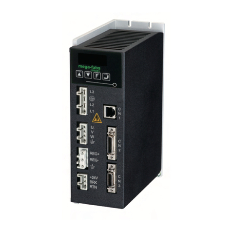
Advanced Motion Controls 12A8 Assembly instructions

-~
ARTISAN
®
~I
TECHNOLOGY
GROUP
Your definitive source
for
quality
pre-owned
equipment.
Artisan Technology
Group
Full-service,
independent
repair
center
with
experienced
engineers
and
technicians
on staff.
We
buy
your
excess,
underutilized,
and
idle
equipment
along
with
credit
for
buybacks
and
trade-ins
.
Custom
engineering
so
your
equipment
works
exactly as
you
specify.
•
Critical
and
expedited
services
•
Leasing
/
Rentals/
Demos
• In
stock/
Ready-to-ship
•
!TAR-certified
secure
asset
solutions
Expert
team
ITrust
guarantee
I
100%
satisfaction
All
tr
ademarks,
br
a
nd
names, a
nd
br
a
nd
s a
pp
earing here
in
are
th
e property of
th
e
ir
r
es
pecti
ve
ow
ner
s.
Find the Advanced Motion Controls 12A8E at our website: Click HERE

Everything’s possible.
www.a-m-c.com
Hardware
Installation Manual
AZ Analog Drives
for Servo Systems
MNALAZIN-02 Artisan Technology Group - Quality Instrumentation ... Guaranteed | (888) 88-SOURCE | www.artisantg.com

MNALAZIN-02 ii
Preface
ADVANCED Motion Controls constantly strives to improve all of its products. We review the information in
this document regularly and we welcome any suggestions for improvement. We reserve the right to modify
equipment and documentation without prior notice.
For the most recent software, the latest revisions of this manual, and copies of compliance and
declarations of conformity, visit the company’s website at www.a-m-c.com. Otherwise, contact the
company directly at:
ADVANCED Motion Controls •3805 Calle Tecate Camarillo, CA •93012-5068 USA
Agency Compliances
The company holds original documents for the following:
•UL 508c, file number E140173
•Electromagnetic Compatibility, EMC Directive - 2004/108/EC
EN61000-6-2:2001
EN61000-6-4:2001
EN61000-3-2:2000
EN61000-3-3:1995/A1:2001
•Electrical Safety, Low Voltage Directive - 72/23/EEC
EN 60 204-1 (IEC 60 204-1)
•Reduction of Hazardous Substances (RoHS), 2002/95/EC
Trademarks
ADVANCED Motion Controls™, the combined isosceles trapezoid/right triangle logo, DIGIFLEX®,
DIGIFLEX® Performance™ and DriveWare™ are either registered trademarks or trademarks of
ADVANCED Motion Controls in the United States and/or other countries. All other trademarks are the
property of their respective owners.
Related Documentation
•Product datasheet specific for your drive, available for download at www.a-m-c.com.
Artisan Technology Group - Quality Instrumentation ... Guaranteed | (888) 88-SOURCE | www.artisantg.com

/
iii MNALAZIN-02
Attention Symbols
The following symbols are used throughout this document to draw attention to important operating
information, special instructions, and cautionary warnings. The section below outlines the overall directive
of each symbol and what type of information the accompanying text is relaying.
Revision History
Document ID Revision # Date Changes
MNALAZIN-01 19/2008 AZ Install Manual First Release
MNALAZIN-02 210/31/2008 - Updated Pads Layout Diagram, Figure 3.4
- Updated Pin Layout Diagram, Figure 2.4
- Added Tachometer Velocity information (also see page 10, page 30, and page 33)
© 2008 ADVANCED Motion Controls. All rights reserved.
Note - Pertinent information that clarifies a process, operation, or ease-
of-use preparations regarding the product.
Notice - Required instruction necessary to ensure successful completion
of a task or procedure.
Caution - Instructs and directs you to avoid damaging equipment.
Warning - Instructs and directs you to avoid harming yourself.
Danger - Presents information you must heed to avoid serious injury or
death.
Note
Artisan Technology Group - Quality Instrumentation ... Guaranteed | (888) 88-SOURCE | www.artisantg.com

MNALAZIN-02 iv
Contents
1 Safety 1
General Safety Overview . . . . . . . . . . . . . . . . . . . . . . . . . . . . . . . . . . . 1
2 Products and System Requirements 4
AZ Drive Family Overview . . . . . . . . . . . . . . . . . . . . . . . . . . . . . . . . . . . 4
Drive Datasheet . . . . . . . . . . . . . . . . . . . . . . . . . . . . . . . . . . . . . . . 4
Products Covered . . . . . . . . . . . . . . . . . . . . . . . . . . . . . . . . . . . . . . . . . 5
Control Modes . . . . . . . . . . . . . . . . . . . . . . . . . . . . . . . . . . . . . . . . . . . . 6
Current (Torque) . . . . . . . . . . . . . . . . . . . . . . . . . . . . . . . . . . . . . . . 6
Open Loop (PWM Duty Cycle) . . . . . . . . . . . . . . . . . . . . . . . . . . . 6
Hall Velocity . . . . . . . . . . . . . . . . . . . . . . . . . . . . . . . . . . . . . . . . . . 6
Encoder Velocity . . . . . . . . . . . . . . . . . . . . . . . . . . . . . . . . . . . . . . 7
Tachometer Velocity . . . . . . . . . . . . . . . . . . . . . . . . . . . . . . . . . . . 7
Feedback Supported . . . . . . . . . . . . . . . . . . . . . . . . . . . . . . . . . . . . . . . 7
Feedback Polarity . . . . . . . . . . . . . . . . . . . . . . . . . . . . . . . . . . . . . 8
Hall Sensors . . . . . . . . . . . . . . . . . . . . . . . . . . . . . . . . . . . . . . . . . . . 8
Using a Single Phase Motor with a Three Phase Drive . . . . 9
Encoder Feedback . . . . . . . . . . . . . . . . . . . . . . . . . . . . . . . . . . . 10
Tachometer Feedback . . . . . . . . . . . . . . . . . . . . . . . . . . . . . . . . 10
Pin Layout . . . . . . . . . . . . . . . . . . . . . . . . . . . . . . . . . . . . . . . . . . . . . . . 11
Single Phase (Brushed, Voice Coil, Inductive Load) Drives . . . . . . . 12
AZxxA8 . . . . . . . . . . . . . . . . . . . . . . . . . . . . . . . . . . . . . . . . . . . . . . 12
AZxxA8DDC . . . . . . . . . . . . . . . . . . . . . . . . . . . . . . . . . . . . . . . . . . 12
Block Diagrams . . . . . . . . . . . . . . . . . . . . . . . . . . . . . . . . . . . . . . . 12
Pinouts . . . . . . . . . . . . . . . . . . . . . . . . . . . . . . . . . . . . . . . . . . . . . . 12
Three Phase (Brushless) Drives . . . . . . . . . . . . . . . . . . . . . . . . . . . . . . . 13
Artisan Technology Group - Quality Instrumentation ... Guaranteed | (888) 88-SOURCE | www.artisantg.com

MNALAZIN-02 v
/
AZBxxA8 . . . . . . . . . . . . . . . . . . . . . . . . . . . . . . . . . . . . . . . . . . . . . 13
AZBExxA8 . . . . . . . . . . . . . . . . . . . . . . . . . . . . . . . . . . . . . . . . . . . . 13
AZBDCxxA8 . . . . . . . . . . . . . . . . . . . . . . . . . . . . . . . . . . . . . . . . . . 13
AZBHxxA8 . . . . . . . . . . . . . . . . . . . . . . . . . . . . . . . . . . . . . . . . . . . . 13
Block Diagrams . . . . . . . . . . . . . . . . . . . . . . . . . . . . . . . . . . . . . . . 13
Pinouts . . . . . . . . . . . . . . . . . . . . . . . . . . . . . . . . . . . . . . . . . . . . . . 14
System Requirements . . . . . . . . . . . . . . . . . . . . . . . . . . . . . . . . . . . . . . 14
Specifications Check . . . . . . . . . . . . . . . . . . . . . . . . . . . . . . . . . . 14
Motor Specifications . . . . . . . . . . . . . . . . . . . . . . . . . . . . . . . . . . 15
Power Supply Specifications . . . . . . . . . . . . . . . . . . . . . . . . . . . . 16
Environment . . . . . . . . . . . . . . . . . . . . . . . . . . . . . . . . . . . . . . . . . 17
Ambient Temperature Range and Thermal Data . . . . . . 17
Shock/Vibrations . . . . . . . . . . . . . . . . . . . . . . . . . . . . . . . . . . 17
3 Integration in the Servo System 18
Grounding . . . . . . . . . . . . . . . . . . . . . . . . . . . . . . . . . . . . . . . . . . . . . . . 18
Wiring . . . . . . . . . . . . . . . . . . . . . . . . . . . . . . . . . . . . . . . . . . . . . . . . . . . 19
Wire Gauge . . . . . . . . . . . . . . . . . . . . . . . . . . . . . . . . . . . . . . . . . . 19
Motor Wires . . . . . . . . . . . . . . . . . . . . . . . . . . . . . . . . . . . . . . . . . . 20
Power Supply Wires . . . . . . . . . . . . . . . . . . . . . . . . . . . . . . . . . . . 20
Feedback Wires . . . . . . . . . . . . . . . . . . . . . . . . . . . . . . . . . . . . . . 20
Input Reference Wires . . . . . . . . . . . . . . . . . . . . . . . . . . . . . . . . . 21
Noise Suppression . . . . . . . . . . . . . . . . . . . . . . . . . . . . . . . . . . . . . . . . . 22
AC Line Filter . . . . . . . . . . . . . . . . . . . . . . . . . . . . . . . . . . . . . . . . . 22
Ferrite Suppression Cores . . . . . . . . . . . . . . . . . . . . . . . . . . . . . . . 22
Inductive Filter Cards . . . . . . . . . . . . . . . . . . . . . . . . . . . . . . . . . . 22
Mounting . . . . . . . . . . . . . . . . . . . . . . . . . . . . . . . . . . . . . . . . . . . . . . . . 23
Mounting Card . . . . . . . . . . . . . . . . . . . . . . . . . . . . . . . . . . . . . . . 23
PCB Mounting Options . . . . . . . . . . . . . . . . . . . . . . . . . . . . . . . . . 24
Mating Connectors . . . . . . . . . . . . . . . . . . . . . . . . . . . . . . . 24
Soldering . . . . . . . . . . . . . . . . . . . . . . . . . . . . . . . . . . . . . . . . 25
Screw Mounting . . . . . . . . . . . . . . . . . . . . . . . . . . . . . . . . . . 25
PCB Design . . . . . . . . . . . . . . . . . . . . . . . . . . . . . . . . . . . . . . . . . . . . . . 26
Trace Width and Routing . . . . . . . . . . . . . . . . . . . . . . . . . . . . . . . 26
Interface Circuitry Examples . . . . . . . . . . . . . . . . . . . . . . . . . . . . . . . . 27
DC Power Input . . . . . . . . . . . . . . . . . . . . . . . . . . . . . . . . . . 27
Motor Power Output . . . . . . . . . . . . . . . . . . . . . . . . . . . . . . 28
Hall Sensor Inputs . . . . . . . . . . . . . . . . . . . . . . . . . . . . . . . . . 29
Artisan Technology Group - Quality Instrumentation ... Guaranteed | (888) 88-SOURCE | www.artisantg.com

MNALAZIN-02 vi
/
Encoder Inputs . . . . . . . . . . . . . . . . . . . . . . . . . . . . . . . . . . . 29
Tachometer Input . . . . . . . . . . . . . . . . . . . . . . . . . . . . . . . . . 30
Offset Input . . . . . . . . . . . . . . . . . . . . . . . . . . . . . . . . . . . . . . 30
4 Operation 31
Getting Started . . . . . . . . . . . . . . . . . . . . . . . . . . . . . . . . . . . . . . . . . . . 31
Input/Output Pin Functions . . . . . . . . . . . . . . . . . . . . . . . . . . . . . 31
Current Monitor Output . . . . . . . . . . . . . . . . . . . . . . . . . . . . 31
Current Reference Output . . . . . . . . . . . . . . . . . . . . . . . . . 31
Fault Output . . . . . . . . . . . . . . . . . . . . . . . . . . . . . . . . . . . . . 32
Inhibit Input . . . . . . . . . . . . . . . . . . . . . . . . . . . . . . . . . . . . . . 32
Low Power Supply Output for Hall Sensors . . . . . . . . . . . . 32
Velocity Monitor Output . . . . . . . . . . . . . . . . . . . . . . . . . . . 33
Tachometer Input . . . . . . . . . . . . . . . . . . . . . . . . . . . . . . . . . 33
Initial Setup . . . . . . . . . . . . . . . . . . . . . . . . . . . . . . . . . . . . . . . . . . 33
Current (Torque) Mode Test . . . . . . . . . . . . . . . . . . . . . . . . . . . . 33
Connections Test . . . . . . . . . . . . . . . . . . . . . . . . . . . . . . . . . 34
Power Supply . . . . . . . . . . . . . . . . . . . . . . . . . . . . . . . . . . . . 34
Input Command Wiring . . . . . . . . . . . . . . . . . . . . . . . . . . . . 34
Hall Sensors . . . . . . . . . . . . . . . . . . . . . . . . . . . . . . . . . . . . . . 35
Motor . . . . . . . . . . . . . . . . . . . . . . . . . . . . . . . . . . . . . . . . . . . 35
Applying a Command (Analog Input) . . . . . . . . . . . . . . . 35
A Specifications 38
Specifications Tables . . . . . . . . . . . . . . . . . . . . . . . . . . . . . . . . . . . . . . 38
B Troubleshooting 41
Fault Conditions and Symptoms . . . . . . . . . . . . . . . . . . . . . . . . . . . . . 41
Over-Temperature . . . . . . . . . . . . . . . . . . . . . . . . . . . . . . . . 41
Over-Voltage Shutdown . . . . . . . . . . . . . . . . . . . . . . . . . . . 41
Under-Voltage Shutdown . . . . . . . . . . . . . . . . . . . . . . . . . . 42
Short Circuit Fault . . . . . . . . . . . . . . . . . . . . . . . . . . . . . . . . . 42
Invalid Hall Sensor State (Brushless Drives only) . . . . . . . . . 42
Artisan Technology Group - Quality Instrumentation ... Guaranteed | (888) 88-SOURCE | www.artisantg.com

MNALAZIN-02 vii
/
Inhibit Input . . . . . . . . . . . . . . . . . . . . . . . . . . . . . . . . . . . . . . 42
Power-On Reset . . . . . . . . . . . . . . . . . . . . . . . . . . . . . . . . . . 42
Overload . . . . . . . . . . . . . . . . . . . . . . . . . . . . . . . . . . . . . . . . . . . . 42
Over-Current . . . . . . . . . . . . . . . . . . . . . . . . . . . . . . . . . . . . . . . . . 42
Motor Problems . . . . . . . . . . . . . . . . . . . . . . . . . . . . . . . . . . . . . . . 43
Causes of Erratic Operation . . . . . . . . . . . . . . . . . . . . . . . . . . . . 43
Technical Support . . . . . . . . . . . . . . . . . . . . . . . . . . . . . . . . . . . . . . . . . 44
Drive Model Information . . . . . . . . . . . . . . . . . . . . . . . . . . . . . . . 44
Product Label Description . . . . . . . . . . . . . . . . . . . . . . . . . . . . . . 44
Warranty Returns and Factory Help . . . . . . . . . . . . . . . . . . . . . . 45
Index I
Artisan Technology Group - Quality Instrumentation ... Guaranteed | (888) 88-SOURCE | www.artisantg.com

MNALAZIN-02 1
1 Safety
ThissectiondiscussescharacteristicsofyourAZAnalogDrivetoraiseyourawarenessofpotentialrisksand
hazards.Theseverityofconsequencesrangesfromfrustrationofperformance,throughdamagetoequipment,
injuryordeath.Theseconsequences,ofcourse,canbeavoidedbygooddesignandproperinstallationintoyour
mechanism.
General Safety Overview
You must install and operate motion control equipment so that you meet
all applicable safety requirements. Ensure that you identify the relevant
standards and comply with them. Failure to do so may result in damage
to equipment and personal injury.
Read this entire manual prior to attempting to install or operate the drive.
Become familiar with practices and procedures that allow you to
operate these drives safely and effectively. You are responsible for
determining the suitability of this product for the intended application.
The manufacturer is neither responsible nor liable for indirect or
consequential damages resulting from the inappropriate use of this
product.
High-performance motion control equipment can move rapidly with
very high forces. Unexpected motion may occur especially during
product commissioning. Keep clear of any operational machinery and
never touch them while they are working.
InordertoinstallanAZdriveintoaservosystem,youmusthaveathoroughknowledgeand
understandingofbasicelectronics,computersandmechanicsaswellassafetyprecautionsand
practicesrequiredwhendealingwiththepossibilityofhighvoltagesorheavy,strong
equipment.
Observeyourfacility’slock‐out/tag‐outproceduressothatworkcanproceedwithoutresidual
powerstoredinthesystemorunexpectedmovementsbythemachine.
Artisan Technology Group - Quality Instrumentation ... Guaranteed | (888) 88-SOURCE | www.artisantg.com

Keep clear of all exposed power terminals (motor, DC Bus, shunt, DC
power, transformer) when power is applied to the equipment. Follow
these safety guidelines:
•Always turn off the main power and allow sufficient time for
complete discharge before making any connections to the drive.
•Do not rotate the motor shaft without power. The motor acts as a
generator and will charge up the power supply capacitors through
the drive. Excessive speeds may cause over-voltage breakdown in
the power output stage. Note that a drive having an internal power
converter that operates from the high voltage supply will become
operative.
•Do not short the motor leads at high motor speeds. When the motor is
shorted, its own generated voltage may produce a current flow as
high as 10 times the drive current. The short itself may not damage
the drive but may damage the motor. If the connection arcs or
opens while the motor is spinning rapidly, this high voltage pulse flows
back into the drive (due to stored energy in the motor inductance)
and may damage the drive.
•Do not make any connections to any internal circuitry. Only
connections to designated connectors are allowed.
•Do not make any connections to the drive while power is applied.
MNALAZIN-02 2
Safety / General Safety Overview
Do not reverse the power supply leads!
Severe damage will result!
Use sufficient capacitance!
Pulse Width Modulation (PWM) drives require a capacitor on the high
voltage supply to store energy during the PWM switching process.
Insufficient power supply capacitance causes problems particularly with
high inductance motors. During braking much of the stored mechanical
energy is fed back into the power supply and charges its output
capacitor to a higher voltage. If the charge reaches the drive’s over-
voltage shutdown point, output current and braking will cease. At that
time energy stored in the motor inductance continues to flow through
diodes in the drive to further charge the power supply capacitance. The
voltage rise depends upon the power supply capacitance, motor
speed, and inductance.
A 2μH motor at 20 amps can charge a 2000 μF capacitor an additional
30 VDC. An appropriate capacitance is typically 2000 μF/A maximum
output current for a 50 VDC supply.
Artisan Technology Group - Quality Instrumentation ... Guaranteed | (888) 88-SOURCE | www.artisantg.com

MNALAZIN-02 3
Safety / General Safety Overview
Make sure minimum inductance requirements are met!
Pulse Width modulation (PWM) servo drives deliver a pulsed output that
requires a minimum amount of load inductance to ensure that the DC
motor current is properly filtered. The minimum inductance values for
different drive types are shown in the individual data sheet
specifications. If the drive is operated below its maximum rated voltage,
the minimum load inductance requirement may be reduced. Most
servo-motors have enough winding inductance. Some types of motors
(e.g. "basket-wound", "pancake", etc.) do not have a conventional iron
core rotor, so the winding inductance is usually less than 50 μH.
If the motor inductance value is less than the minimum required for the
selected drive, use an external filter card.
Artisan Technology Group - Quality Instrumentation ... Guaranteed | (888) 88-SOURCE | www.artisantg.com

MNALAZIN-02 4
2 Products and System Requirements
Thisdocumentisintendedasaguideandgeneraloverviewinselecting,installing,andoperatinganAZservo
drive.Containedwithinareinstructionsonsystemintegration,wiring,drive‐setup,andstandardoperating
methods.
AZ Drive Family Overview
ThefamilyofAZanalogdrivesaredesignedtoofferthesamehighperformanceandaccuracy
oflargerdrives,butinaspace‐savingPCB‐mountarchitecture.Byutilizinghighdensitypower
devices,dualsidedPCBboards,andcreativedesignAZdrivesareidealforapplicationswith
limitedsizeandweightconstraints.
TheAZdrivefamilycontainsdrivesthatcanpowerSinglePhase(brushed)andThreePhase
(brushless)motors.AZdrivesarepoweredoffasingleunregulatedDCpowersupply,and
provideavarietyofcontrolandfeedbackoptions.Thedrivesaccepteithera+/‐10Vanalog
signaloraPWMandDirectionsignalasinput.Adigitalcontrollercanbeusedtocommandand
interactwithAZdrives,andanumberofinput/outputpinsareavailableforparameter
observationanddriveconfiguration.
Drive Datasheet
EachAZanalogdrivehasaseparatedatasheetthatcontainsimportantinformationonthe
modesandproduct‐specificfeaturesavailablewiththatparticulardrive.Thedatasheetistobe
usedinconjunctionwiththismanualforsystemdesignandinstallation.
In order to avoid damage to equipment, only after a thorough reading
and understanding of this manual and the specific datasheet of the AZ
drive being used should you attempt to install and operate the drive.
Artisan Technology Group - Quality Instrumentation ... Guaranteed | (888) 88-SOURCE | www.artisantg.com

FIGURE 2.1 AZ Part Numbering Structure
A
Revision
Peak Voltage
Peak Current
-
Additional Options
Blank: Current Mode only
E: Encoder Velocity Mode Available
Maximum peak current rating in Amps Peak voltage rating scaled 1:10 in Volts
Assigned a letter (A through Z) by manufacturer
PWM Command
H: Hall velocity Mode Available
Brushed DriveBlank:
AZ Analog Drive Series
AZ
Drive Type
DDC: Brushed Drive, PWM Command
B: Brushless drive
BDC: Brushless Drive, PWM Command
Feedback Supported
MNALAZIN-02 5
Products and System Requirements / Products Covered
Products Covered
Theproductscoveredinthismanualadheretothefollowingpartnumberingstructure.
However,additionalfeaturesand/oroptionsarereadilyavailableforOEM’swithsufficient
orderingvolume.FeelfreetocontactADVANCEDMotionControlsforfurtherinformation.
Ingeneral,theAZfamilyofanalogdrivescanbedividedintotop‐levelcategoriesbasedonthe
peakcurrentratingofthedrive.Thesecategoriescanbefurtherseparatedintosubdivisions
basedonspecificationssuchaswhetheradriveusesanalogorPWMinput,thetypeof
motor(s)supported,andthefeedbackavailableonthedrive.
TABLE 2.1 Power Specifications
Power Specifications
Description Units AZxx6A8 AZxx12A8 AZxx20A8
DC Supply Voltage Range VDC 20-80 10-80
DC Bus Over Voltage Limit VDC 88
DC Bus Under Voltage Limit VDC 18 9
Maximum Peak Output Current A 6 12 20
Maximum Continuous Output Current A 3 6 12
Maximum Power Dissipation at Continuous Current W12 24 48
Minimum Load Inductance μH100
Switching Frequency kHz 31
TABLE 2.2
Control Specifications
Description AZ AZB AZ_DDC AZBDC AZBE AZBH
Command Sources +/- 10V Analog +/- 10V Analog PWM and Direction PWM and Direction +/- 10V Analog +/- 10V Analog
Commutation Methods -Trapezoidal -Trapezoidal Trapezoidal Trapezoidal
Control Modes Current Current Current Current Current, Open Loop, Encoder
Velocity, Tachometer Velocity
Current, Open Loop, Hall
Velocity, Tachometer Velocity
Motors Supported Single Phase Three Phase
Single Phase Single Phase Three Phase
Single Phase
Three Phase
Single Phase
Three Phase
Single Phase
Control Specifications
The values and diagrams presented in this chapter are a general drive
"overview". For more detailed information, consult the datasheet for a
specific drive.
Artisan Technology Group - Quality Instrumentation ... Guaranteed | (888) 88-SOURCE | www.artisantg.com

MNALAZIN-02 6
Products and System Requirements / Control Modes
Control Modes
TheAZfamilyofanalogdrivesoffersavarietyofdifferentcontrolmethods.Whilesomedrives
intheseriesaredesignedtooperatesolelyinonemode,onotherdrivesitispossibletoselect
thecontrolmethodbyDIPswitchsettings.Consultthedatasheetforthedriveinusetosee
whichmodesareavailableforuse.
Thenameofthemodereferstowhichservoloopisbeingclosedinthedrive,nottheend‐result
oftheapplication.Forinstance,adriveoperatinginCurrent(Torque)Modemaybeusedfora
positioningapplicationiftheexternalcontrollerisclosingthepositionloop.Oftentimes,mode
selectionwillbedependentontherequirementsandcapabilitiesofthecontrollerbeingused
withthedriveaswellastheend‐resultapplication.
Current (Torque)
InCurrent(Torque)Mode,theinputcommandvoltagecontrolstheoutputcurrent.Thedrive
willadjusttheoutputdutycycletomaintainthecommandedoutputcurrent.Thismodeisused
tocontroltorqueforrotarymotors(forceforlinearmotors),butthemotorspeedisnot
controlled.Theoutputcurrentcanbemonitoredthroughananalogcurrentmonitoroutput
pin.Thevoltagevaluereadatthe“CurrentMonitorOutput”canbemultipliedbyascaling
factorfoundonthedrivedatasheettodeterminetheactualoutputcurrent.AllAZdrivesare
abletooperateinCurrent(Torque)Mode.
While in Current (Torque) Mode, the drive will maintain a commanded
torque output to the motor based on the input reference command.
Sudden changes in the motor load may cause the drive to be outputting
a high torque command with little load resistance, causing the motor to
spin rapidly. Therefore, Current (Torque) Mode is recommended for
applications using a digital position controller to maintain system stability.
Open Loop (PWM Duty Cycle)
InOpenLoop(PWMDutyCycle)Mode,theinputcommandvoltagecontrolstheoutputPWM
dutycycleofthedrive,indirectlycontrollingtheoutputvoltage.However,anyfluctuationsof
theDCpowersupplyvoltagewillaffectthevoltageoutputtothemotor.Thismodeisavailable
asaDIPswitchselectablemodeonAZBExxA8andAZBHxxA8drives.
This mode is recommended as a method of controlling the motor
velocity when precise velocity control is not critical to the application,
and when actual velocity feedback is unavailable.
Hall Velocity
InHallVelocityMode,theinputcommandvoltagecontrolsthemotorvelocity,withtheHall
Sensorfrequencyclosingthevelocityloop.Ananalogvelocitymonitoroutputallows
observationoftheactualmotorspeedthroughaHz/Vscalingfactorfoundonthedrive
datasheet.Thevoltagevaluereadatthevelocitymonitoroutputcanbeusedtodeterminethe
Note
Note
Artisan Technology Group - Quality Instrumentation ... Guaranteed | (888) 88-SOURCE | www.artisantg.com

MNALAZIN-02 7
Products and System Requirements / Control Modes
motorRPMthroughthescalingfactor.See“VelocityMonitorOutput”onpage33forthemotor
RPMequation.ThismodeisavailableasaDIPswitchselectablemodeonAZBHxxA8drives.
Due to the inherent low resolution of motor mounted Hall Sensors, Hall
Velocity Mode is not recommended for low-speed applications below
300 rpm for a 6-pole motor, 600 rpm for a 4-pole motor, or 900 rpm for a
2-pole motor. Hall Velocity Mode is better suited for velocity control
applications where the motor will be spinning at higher speeds.
Encoder Velocity
InEncoderVelocityMode,theinputcommandcontrolsthemotorvelocity,withthefrequency
oftheencoderpulsesclosingthevelocityloop.Ananalogvelocitymonitoroutputallows
observationoftheactualmotorspeedthroughakHz/Vscalingfactorfoundonthedrive
datasheet.Thevoltagevaluereadatthevelocitymonitoroutputcanbeusedtodeterminethe
motorRPMthroughthescalingfactor.See“VelocityMonitorOutput”onpage33forthemotor
RPMequation.ThismodeisavailableasaDIPswitchselectablemodeonAZBExxA8drives.
The high resolution of motor mounted encoders allows for excellent
velocity control and smooth motion at all speeds. Encoder Velocity
mode should be used for applications requiring precise and accurate
velocity control, and is especially useful in applications where low-speed
smoothness is the objective.
Tachometer Velocity
InTachometerVelocityMode,theinputcommandvoltagecontrolsthemotorvelocity.This
modeusesanexternalDCtachometertoclosethevelocityloop.ThedrivetranslatestheDC
voltagefromthetachometerintomotorspeedanddirectioninformation.Thismodeis
availableasaDIPswitchselectablemodeonAZBExxA8andAZBHxxA8drives.
DC Tachometers have infinite resolution, allowing for extremely accurate
velocity control. However, they also may be susceptible to electrical
noise, most notably at low speeds.
Note
Note
Note
Artisan Technology Group - Quality Instrumentation ... Guaranteed | (888) 88-SOURCE | www.artisantg.com

MNALAZIN-02 8
Products and System Requirements / Feedback Supported
Feedback Supported
ThereareanumberofdifferentfeedbackoptionsavailableintheAZfamilyofanalogdrives.
Thefeedbackelementcanbeanydevicecapableofgeneratingavoltagesignalproportionalto
current,velocity,position,oranyparameterofinterest.Suchsignalscanbeprovideddirectly
byapotentiometerorindirectlybyotherfeedbackdevicessuchasHallSensorsorEncoders.
TheselatterdevicesmusthavetheirsignalsconvertedtoaDCvoltage,ataskperformedbythe
AZdrivecircuitry.
TABLE 2.3 Feedback Supported
Feedback Supported
Description AZ AZB AZ_DDC AZBDC AZBE AZBH
Hall Sensors for Commutation D D D D
Hall Sensors for Velocity Control D
Single- Ended Incremental Encoder D
Feedback Polarity
Thefeedbackelementmustbeconnectedfornegativefeedback.Thiswillcauseadifference
betweenthecommandsignalandthefeedbacksignal,calledtheerrorsignal.Thedrive
comparesthefeedbacksignaltothecommandsignaltoproducetherequiredoutputtothe
loadbycontinuallyreducingtheerrorsignaltozero.ForAZdrives,thisbecomesimportant
whenusing“EncoderFeedback”and“HallSensors”,asconnectingthesefeedbackelements
forpositivefeedbackwillleadtoamotor"run‐away"condition.Inacasewherethefeedback
linesareconnectedtothedrivewiththewrongpolarityineitherHallVelocityorEncoder
VelocityMode,thedrivewillattempttocorrectthe"errorsignal"byapplyingmorecommand
tothemotor.Withthewrongfeedbackpolarity,thiswillresultinapositivefeedbackrun‐away
condition.Tocorrectthis,eitherchangetheorderthatthefeedbacklinesareconnectedtothe
drive,orchangeSwitch4ontheDIPswitchbanktotheoppositesettingtoreversetheinternal
feedbackvelocitypolarity.SeethedrivedatasheetformoreinformationonDIPswitchsettings.
Hall Sensors
DCThreePhase(Brushless)AZdrivesusesingle‐endedHallSensorsforcommutation
feedback,andinthespecialcaseoftheAZBHxxA8drives,forvelocitycontrol.TheHallSensors
(typicallythree)arebuiltintothemotortodetectthepositionoftherotormagneticfield.These
sensorsaremountedsuchthattheyeachgenerateasquarewavewith120‐degreephase
differenceoveroneelectricalcycleofthemotor.Dependingonthemotorpolecount,there
maybemorethanoneelectricalcycleforeverymotorrevolution.Foreveryactualmechanical
motorrevolution,thenumberofelectricalcycleswillbethenumberofmotorpolesdividedby
2.Forexample:
•a6‐polemotorcontains3electricalcyclespermotorrevolution
•a4‐polemotorcontains2electricalcyclespermotorrevolution
•a2‐polemotorcontains1electricalcyclepermotorrevolution.
ThedrivepowerstwoofthethreemotorphaseswithDCcurrentduringeachspecificHall
Sensorstate:
Artisan Technology Group - Quality Instrumentation ... Guaranteed | (888) 88-SOURCE | www.artisantg.com

FIGURE 2.2 Hall Sensor Commutation and Motor Phase Current for 120-Degree Phasing
Electrical Degrees
Motor Phase
Current
060 120 180 240 300 360
Hall A
Hall B
Hall C
High (1)
Low (0)
High (1)
Low (0)
High (1)
Low (0)
Phase A
Phase B
Phase C
Hall Sensor
Commutation
Electrical Degrees
060 120 180 240 300 360
High
Low
High
Low
High
Low
MNALAZIN-02 9
Products and System Requirements / Feedback Supported
Thetablebelowshowsthevalidcommutationstatesforboth120‐degreeand60‐degree
phasing.
TABLE 2.4 Commutation Sequence Table
60 Degree 120 Degree Motor
Hall 1 Hall 2 Hall 3 Hall 1 Hall 2 Hall 3 Phase A Phase B Phase C
Valid
1 0 0 1 0 0 HIGH -LOW
1 1 0 1 1 0 - HIGH LOW
1 1 1 0 1 0 LOW HIGH -
0 1 1 0 1 1 LOW -HIGH
0 0 1 0 0 1 - LOW HIGH
0 0 0 1 0 1 HIGH LOW -
Invalid 1 0 1 1 1 1 - - -
0 1 0 0 0 0 - - -
Bydefault,AZdrivesarealwayssetto120‐degreephasing.Threephase(Brushless)drivesdo
howeverhaveasurface‐mountjumper(JE2)onthedrivePCBthatcanberemovedto
manuallysetthedriveto60‐degreephasing.
Using a Single Phase Motor with a Three Phase Drive ThreePhase(Brushless)
drivesarealsocompatiblewithSinglePhase(Brushed)motors.However,becausethereareno
HallSensorsonabrushedmotor,oneofthefollowingcourseofactionsmustbetakento
properlycommutatethedrive:
•RemovetheJE2jumpertosetthedrivefor60‐degreephasing.LeavealltheHallSensor
inputsonthedriveopen.Theseinputsareinternallypulledhighto+5V,creatinga"1‐1‐1"
Artisan Technology Group - Quality Instrumentation ... Guaranteed | (888) 88-SOURCE | www.artisantg.com

MNALAZIN-02 10
Products and System Requirements / Feedback Supported
commutationstate(seeTable2.4above)whichisavalidstatein60‐degreephasing.
Connectonlytwoofthemotoroutputwires,MotorAandMotorB.
or:
•TieoneoftheHallSensorinputsontheAZdrivetosignalground.SincetheHallSensor
inputsarebydefaultinternallybroughthighto+5V,thiswillputtheAZdriveina
commutationstatewheretwoHallinputsarehigh,andoneislow(asshowninTable2.4,
havingallthreeHallinputspulledhighisaninvalidcommutationstatein120‐degree
phasing).DependingonwhichHallSensorinputistiedtoground,consultTable2.4above
todeterminewhichtwomotoroutputwireswillbeconductingcurrentforthatspecific
commutationstate.
FIGURE 2.3 Encoder Feedback Signals
Encoder-A
Encoder-B
Encoder-A
Encoder-B
Example 1: Encoder-A precedes
Encoder-B. The pulses arrive at
a certain frequency, providing
speed and directional
information to the drive.
Example 2: Encoder-B precedes
Encoder-A, meaning the direction
is opposite from Example 1. The
signal frequency is also higher,
meaning the speed is greater
than in Example 1.
Encoder Feedback
AZBExxA8drivesutilizetwosingle‐endedincrementalencoderinputsforvelocitycontrol.The
encoderprovidesincrementalpositionfeedbackthatcanbeextrapolatedintoveryprecise
velocityinformation.Theencodersignalsarereadas"pulses"thattheAZdriveusesto
essentiallykeeptrackofthemotor’spositionanddirectionofrotation.Basedonthespeedand
orderinwhichthesepulsesarereceivedfromthetwoencodersignals,thedrivecaninterpret
themotorvelocity.Thediagrambelowrepresentsencoder"pulse"signals,showinghow
dependentonwhichsignalisreadfirstandatwhatfrequencythe"pulses"arrive,thespeed
anddirectionofthemotorshaftcanbeextrapolated.
Tachometer Feedback
AZBExxA8andAZBHxxA8drivesoffertheoptionofusingaDCTachometerforvelocitycontrol.
ThetachometerprovidesananalogDCvoltagefeedbacksignalthatisrelatedtotheactual
motorspeedanddirection.Thedrivesubsequentlyadjuststheoutputcurrentbasedonthe
errorbetweenthetachometerfeedbackandtheinputcommandvoltage.Themaximumrange
ofthetachometerfeedbacksignalis±60VDC.
Artisan Technology Group - Quality Instrumentation ... Guaranteed | (888) 88-SOURCE | www.artisantg.com

FIGURE 2.4 AZ-series Pin Layouts
PIN 1b PIN 1a
PIN 11a
PIN 11b
PIN 1
PIN 16
P1 - Signal
Connector
P2 - Power
Connector
0.10in [2.54mm]
[55.88mm]
2.20in
0.10in [2.54mm]
PIN 1
PIN 11
PIN 16
P1 - Signal
Connector
P2 - Power
Connector
PIN 1
[2.54mm]
[55.88mm]
2.20in
0.10in
AZ6andAZ12Drives AZ20Drives
MNALAZIN-02 11
Products and System Requirements / Pin Layout
Pin Layout
ThediagramsbelowshowthepinlayoutandlocationonAZdrives,asseenfromthePCB
wherethedriveismounted.NotethatAZ20drivesusesadoublerowforthepowerheader.
Moredetaileddimensionalinformationcanbefoundin“PhysicalDimensions”onpage39and
in“MatingConnectors”onpage24.
Artisan Technology Group - Quality Instrumentation ... Guaranteed | (888) 88-SOURCE | www.artisantg.com

MNALAZIN-02 12
Products and System Requirements / Single Phase (Brushed, Voice Coil, Inductive Load) Drives
Single Phase (Brushed, Voice Coil, Inductive Load) Drives
AZxxA8
•Designedtodrivebrush‐typemotors
witha+/‐10Vanaloginput.
•Current(Torque)Mode
AZxxA8DDC
•Designedtodrivebrush‐typemotors
withaPWMinputcommand.
•Current(Torque)Mode
Block Diagrams
+/-10 V Analog
Input
Current Feedback
Motor Feedback
Brushed
Motor
Current Command
Drive
Logic
Power Stage
AZ SERVO DRIVE
Controller
PWM Input
Current Feedback
Current Command
Drive
Logic
Power Stage
Brushed
Motor
AZ Servo Drive
Controller
FIGURE 2.5.1 AZxxA8DDC Drive Structure
FIGURE 2.5 AZxxA8 Drive Structure
Pinouts
AZ6/AZ12/AZ20
Analog Command
AZ6/AZ12/AZ20
PWM Command
Pin Description Description
1 +REF IN PWM IN
2 SIGNAL GROUND SIGNAL GROUND
3−REF IN DIR IN
4 CURRENT MONITOR CURRENT MONITOR
5 INHIBIT IN INHIBIT IN
6 RESERVED RESERVED
7 SIGNAL GROUND SIGNAL GROUND
8 RESERVED RESERVED
9 RESERVED RESERVED
10 RESERVED RESERVED
11 CURRENT REF OUT CURRENT REF OUT
12 FAULT OUT FAULT OUT
13 RESERVED RESERVED
14 RESERVED RESERVED
15 RESERVED RESERVED
16 RESERVED RESERVED
AZ6 / AZ12
All Configurations
Pin Description
1HIGH VOLTAGE
2
3 NC (KEY)
4POWER
GROUND
5
6RESERVED
7
8MOTOR B
9
10 MOTOR A
11
AZ20
All Configurations
Pin Description
1b 1a HIGH VOLTAGE
2b 2a
3b 3a RESERVED (3B)
NC - KEY (3a)
4b 4a POWER
GROUND
5b 5a
6b 6a RESERVED
7b 7a
8a 8b MOTOR B
9b 9a
10b 10a MOTOR A
11b 11a
TABLE 2.5.1 Single Phase Power Connector
TABLE 2.5 Single Phase Signal Connector
Artisan Technology Group - Quality Instrumentation ... Guaranteed | (888) 88-SOURCE | www.artisantg.com
This manual suits for next models
1
Table of contents
Popular Servo Drive manuals by other brands
HPI Racing
HPI Racing SF-50 instructions
Dongbu Robot
Dongbu Robot HERKULEX DRS-0101 user manual
Leadshine Technology Co.
Leadshine Technology Co. DCS303 user manual
Kinco
Kinco CD420 user manual

NTI AG
NTI AG LinMot C1250 Series installation guide

Mitsubishi Electric
Mitsubishi Electric MR-JET- G Series user manual
