Advanced Poly-Packaging T-200 User manual

T-200
Table Top Bagger/Sealer
____________________________________________________________________________
Operation Guide, Ver 1

Acknowledgments
Manual written by: Stuart Baker & Joe Kalil
Copyright
Copyright 2/2000, Advanced Poly-Packaging, Inc. All rights reserved. This manual and the program operating the equipment
described in it are copyrighted. You may not copy this manual in whole or part without written consent of Advanced Poly-
Packaging, Inc.
All information pertaining to the promotion, sale, distribution, operation, and maintenance of the T-200 Table Top Bagger/Sealer
including this manual, drawings, schematic, wiring diagrams, VHS video tapes, brochures, specification sheets, figures, charts, or
any other information, due to its proprietary design and manufacture remain the property of Advanced Poly Packaging, Inc.
Unauthorized duplication, distribution, or disclosure to third parties without the expresses permission of Advanced Poly
Packaging, Inc. is strictly prohibited.
Trademarks
T-200 Table Top Bagger/Sealer is a trademark of Advanced Poly-Packaging, Inc. Advanced Poly-Packaging, Inc. owns also the
following trademarks: T-1000, Advanced Poly-Bags, Twin-Seal, Advanced Poly-Pack, Advanced Poly-Bag, Blist-a-Bag, Ti-
1000 Inline Thermal Printer and Ti-2000 Dual Inline Thermal Transfer Printer, Ultra-Feed, Ultra-Count, Flip-Series, Seal-a-Print,
Roll-a-Print, Anti-Stick Shield.
Warranty
Warranty period is one year except for the heater wire and other items considered “wear” items. The warranty commences on the
date of delivery of the equipment to the purchaser.
APPI warrants to the Purchaser that the equipment is free from defects in workmanship or material under normal use and service.
During the warranty period, APPI agrees to repair or replace, at its sole option, without charge to Purchaser, any defective
component part of the equipment. To obtain service, Purchaser must return the equipment or component to APPI or an
authorized APPI distributor or service representative in an adequate container for shipping. Any shipping charges, insurance, or
other fees must be paid by Purchaser and all risk for the equipment shall remain with Purchaser until such time as APPI takes
receipt of the equipment. Upon receipt, APPI, the authorized distributor or service representative will promptly repair or replace
the defective component and then return the equipment or component to Purchaser, shipping charges, insurance, and additional
fees prepaid. APPI may use reconditioned or like new parts or units, at its sole option, when repairing any component or
equipment.
Repaired products shall carry the same amount of outstanding warranty as from original purchase. Any claim under the warranty
must include a dated proof of delivery. In any event, APPI's liability for defective components or equipment is limited to
repairing or replacing the components.
This warranty is contingent upon proper use of the equipment by Purchaser and does not cover: expendable component parts
such as print heads, rollers, bushings, and the like; or if damage is due to accident, unusual physical, electrical or mechanical
stress, neglect, misuse, failure of electric power, improper environmental conditions, transportation, tampering with or altering of
the equipment, packaging of corrosive or contaminating products or other products damaging to components, and equipment or
components not owned or in the possession of original Purchaser.
APPI will not be liable for loss of production, profits, lost savings, special, incidental, consequential, indirect, or other similar
damages arising from breach of warranty, breach of contract, negligence, or their legal action even if APPI or its agent has been
advised of the possibility of such damages or for any claim brought against the Purchaser by another party.
This warranty allocates risks of equipment failure between Purchaser and APPI. APPI's pricing reflects this allocation of risk
and the limitations of liability contained in this warranty. The warranty set forth above is in lieu of all other express warranties,
whether oral or written. The agents, employees, distributors, and dealers of APPI are not authorized to make modifications to
this warranty, or additional warranties binding on APPI. Accordingly, additional statements such as dealer advertising or
presentations, whether oral or written, do not constitute warranties by APPI and should not be relied upon.
ADVANCED POLY-PACKAGING, INC. (APPI)

Contents
______________________________________________________________________________
Chapter 1, Introduction
1.1 Welcome
1.2 Overview
1.3 Using this Manual
1.4 Special Features
1.5 Available Options
1.6 Special Note on Safety
1.7 Specifications
1.8 Unpacking & Setup
1.9 Operating Environment
Chapter 2, Getting Started
2.1 Air & Power Hookup
2.2 Roll Mounting and Threading
2.3 Main Power
2.4 Operation Tests Prior to Production
2.5 Heat / Dwell Time Setting
2.6 Air / Seal Pressure Adjustments
2.7 Blower Setting
2.8 Funnel Position
2.9 Sealing - Foot Switch or Guard Switch
2.10 Adjustable Shelf
2.11 Pull Tension Adjustments
2.12 Note on Seal Quality
2.13 Totalizing Counter
Chapter 3, Adjustments, Testing & Replacements
3.1 Adding PTFE Anti-Stick, Cleaning Rubber Strip
3.2 Rubber Strip Replacement
3.3 PTFE Anti-Stick Advance
3.4 PTFE Anti-Stick Sheet Replacement
3.5 Heater Element Replacement
3.6 Description of Anti-jam Circuit
3.7 Anti-jam Adjustments / Testing
3.8 Preventative Maintenance
Chapter 4, Parts Identification
4.1 Recommended Spare Parts
4.2 Parts / Component Identification
4.3 Pneumatic Diagram
4.4 Wiring Diagram / Electronics

Chapter 1 Getting Started
_____________________________________________________
Introduction
Welcome
Overview
Using This Manual
Special Features
Available Options
Note on Safety
Specifications
Unpacking & Setup
Operating Environment

1.1 Welcome
Thank you for selecting the T-200 Series Table Top Bagger / Sealer. The T-200 is easy to
operate and quick to set up, making it ideal for long or short packaging runs. Where labor
reduction and fast changeover is important, the Advanced Poly T-200Tabletop Bagger
/ Sealer uses Advanced Poly-Bags(Pre-opened Bags on Rolls), manufactured by
Advanced Poly-Packaging, Inc.
1.2 Overview
The T-200 is designed to package various industrial, medical, molded and food products. With a
wide range of bag sizes (2" x 3" to 11" x 16") and mil thickness (1 mil to 5 mil), the T-200 will
demonstrate to be a versatile bagger.
The T-200 is designed to lower your packaging costs with increased speeds, versatility,
reliability, and simplicity. Instead of sealing with a conventional jaw sealer whereas an operator
is required to pull an individual bag from a carton, then open the bag first even before reaching
for the components to be inserted, the pre-opened bag “pops” open when pulled into position.
Once loaded, the bag can be sealed without having to separate the bag at the perforation. Ideal
for numerous short runs with virtually no production loss for job changeovers since all that is
required is a roll change. Single knob heat, dwell and cool setting adjustments makes setups a
snap.
1.3 Using This Manual
The following manual conventions are frequently used to assist in understanding important
information, alerting the operator of potentially dangerous or damaging practices, and the normal
functions of the T-200 Sealer / Bagger.
Text normal text
Italics Used for emphasis
BOLDFACE Used to identify heading names
!Used to identify important information
CAUTION:Warning messages. To avoid physical harm, damage to equipment or damage to
the product. Be sure to read these messages carefully.
1.4 Special Features of the T-200
The T-200 has been designed with simplicity of operation and ease of maintenance in mind.
The totalizing counter counts cycles of operation and has a reset feature. Press the reset button at
the beginning of each shift or day to record packaging production.
Patented design seal assembly - PTFE Anti-Stick material is only in contact with hot wire during
sealing and is then stripped away from the wire immediately after sealing; reduces contamination
buildup, increases material life, and improves seal integrity.

Double or triple seal quickly and easily - Seal the bag a second time or third time by pulling
down and sealing for consistent placement of seals.
Patented Anti-Jam Device - During the loading and sealing operation, this device detects
obstructions and automatically reverses the pressure bar, discontinuing the cycle operation.
1.5 Available Options
Spare Parts Kit: Additional PTFE Anti-Stick material, heater wire, valve and other components
make this kit a must.
See Chapter 4, Section 4.l for recommended Spare Parts Kit.
Special funnels: Send us your product and we will evaluate the loading to determine the best
funnel design.
Bag deflator: Quickly mounts to the sealer bar squeezing the air from the bag while sealing.
1.6 Special Note on Safety
Although many safety features have been included in the mechanical, electronic, and pneumatic
systems, improper use, improper adjustments, or neglect of preventative maintenance may result
in serious personal injury.
1.7 Specifications
Dimensions: 19.25” wide x 14.675” deep x 21” tall (See Figure 1-1)
Weight: 65 lbs.
Air: 50 psi
Electric: 117V/60Hz or 220V/50Hz
Bag sizes: 2 x 2 up to 11 x 16
Product pass through area: approx. 2.75”
1.8 Unpacking & Setup
The T-200 is shipped completely assembled and in a carton. Remove all tape, banding or packing
materials that secure the machine. To ensure the highest production possible, consider product flow to the
bagger and packaged product flow away from the bagger when positioning the bagger into your
packaging areas.
1.9 Operating Environment
When you choose a location for installation, make sure the area is free of excess dust, dirt, and moisture.

Chapter 2
Getting Started & Equipment Operation
Air & Power Hookup
Roll Mounting and Threading
Main Power
Operation Tests Prior to Production
Heat / Dwell Time Setting
Air / Seal Pressure Adjustments
Blower Setting
Funnel Position
Sealing - Foot Switch or Guard Switch
Adjustable Shelf
Pull Tension Adjustments
Note on Seal Quality
Totalizing Counter

2.1 Air & Power Hookup
The T-200 is equipped with an internal regulator and the air supply should be fed to the T-200 with ¼”
min. O.D. poly tubing. Make the connection at the rear of the sealer. Set the air pressure on the T-200
between 40 and 50 psi.
2.2 Roll mounting and threading
Loosen one of the knobs located on the chuck which secures the roll into position. Mount the roll of bags
onto the bag roll shaft and secure the bag roll into position with the chuck. With the loose web of bags
falling over the rear of the roll, insert the web into the slot above the stainless rear cover and below the
top cover. With the web of bags positioned under the top cover, raise the top cover of the T-200 by lifting
the funnel mounting rods. Pull the web forward through the cover while lowering the top cover. When
the top cover is lowered, the first bag should open by the airflow. The roll shaft is fixed into position
with a pin and will not spin. The roll spins on the fixed shaft. See Threading Diagram,
Figure 2-2.
2.3 Main Power
The power switch is located on the rear right lower side. In the On or “up” position, the switch is
illuminated indicating that power is supplied to the unit.
2.4 Operation / Component Tests Prior to Production
Prior to beginning production, the anti-jam mechanism should be tested by following these procedures:
Test 1: With air applied and the power on, position an object over 1/4” in thickness (a pen or pencil for
example) on the far-left side of the seal bar with the object in contact with the Anti-Stick Shield, but not
pressing in the spring-loaded “U” channel Anti-Stick Shield. Then press the footswitch. The Anti-jam
circuit is working properly if the pressure bar retracts and the heat does not turn on (Orange LED
illuminates when current is applied to the heater element). If the pressure bar does not immediately
retract and heat is applied, do not begin production, and refer to Chapter 3, Section 3.6 for instruction on
Anti-jam Adjustments.
Test 2: With air applied and the power on, position an object over 1/4” in thickness (a pen or pencil for
example) on the far-left side of the seal bar with the object pushing inward on the Anti-Stick Shield.
Ensure that you are pressing in the spring-loaded “U” channel Anti-Stick Shield and then press the
footswitch. The Anti-jam circuit is working properly if the pressure bar does NOT move inward and the
heat does not turn on (Orange LED illuminates when current is applied to the heater element). If the
pressure moves inward and/or heat is applied, do not begin production, and refer to Chapter 3, Section 3.6
for instruction on Anti-jam Adjustments.
Continue these test procedures with the object being moved along the entire seal area length from the left
to the right side of the seal area.

2.5 Heat / Dwell Time Adjustment
Current flows to the heater wire when the sealer bar is gripped against the front plate and spring gripper
assembly. The duration of time that the sealer bar is against the plate can be adjusted by the dwell time
knob located on the left upper front panel. This single knob controls both the heat time and cool time.
Cool time is proportioned according to the seal time. The thickness of the bag and the continuous cycle
speed determines the dwell time setting. When the heater wire is cool, a longer seal time will be required.
After a period of continuous sealing, the seal time can be lowered. After approximately 30 seals in a
short period of time, the heater wire should be heated and at a stable temperature. Adjust the seal time
starting at lower times and increasing in small increments.
Note: Excessive seal time can cause burns in the PTFE Anti-Stick and the bag and decrease the life of the
heater wire.
CAUTION! THE SEAL BAR IS HOT! DO NOT PLACE FINGERS IN THE SEALING AREA.
2.6 Air / Seal Pressure Adjustments
To obtain good consistent seals, air pressure must be adjusted. The pressure valve is located on the rear
of the unit. Typically, the air pressure is set to a constant pressure of 40 to 50 psi. To increase the
pressure, pull the black knob outward, away from the machine and then turn clockwise; then push to knob
inward to lock into position. To decrease pressure, pull the knob outward, turn clockwise and press the
knob inward.
2.7 Blower / Bag Opening
The T-200 Sealer/Bagger is equipped with a 6” wide air knife and flow control valve to ensure that the
bag blow open quickly and consistently. Since the air knife speeds up air, compressed air is conserved.
Adjust the volume of air with the Blower flow control valve located on the rear of the unit (bronze knob).
To slow or reduce the volume of air, turn the knob counterclockwise; to increase the air flow, turn the
knob clockwise. Begin by turning the blower all the way down and increase slightly until the bags blow
open continuously and consistently. Once adjusted, there is a locking nut to prohibit the knob from
loosening.
Note: Excessive air flow with cause the bag to move around and product to possibly spill from the bag.
2.8 Funnel Position
The funnel can be tilted in or out and adjusted closer or further from the bag opening. Typically, the
bottom of the funnel is positioned approximately ½” from top of the bag opening. The funnel bracket
assembly can be pushed inward, closer to the bag dependent upon production dimensions.
Note: If the funnel is too close to the front plate, air flow may be blocked causing the bag not to blow
open.
Caution: To avoid personal injury, do not operate the T-200 without guards, covers and
funnel in position.
2.9 Sealing the Bag / Foot Switch or Guard Switch Operation
Carefully pull the bag downward into the sealing position and load the product by allowing the product to
slide down the funnel.
Once the product is in the bag, the bag can be sealed or left unsealed.

To start the seal operation of the bagger, the operator has two options: 1) footswitch operation or 2) guard
switch operation, described as follows:
1) Foot switch operation: when the footswitch is plugged into the back of the bagger, pressing the
footswitch will begin the operation of the sealer mechanism. The guard switch is disabled when the
footswitch is plugged in.
2) Guard Switch operation: to operate the seal mechanism using the guard switch, the footswitch must
be unplugged and a “key” must be inserted into the footswitch plug located at the rear of the unit. When
the key is plugged in, the guard switch may be used to cycle the machine. With the key in position and
the product is in the bag and the bag is in the desired seal position, press downward on the front center of
the guard to begin the seal operation. The guard is spring-loaded with a micro switch mounted inside the
panel (See Fig. 2-9)
CAUTION! Ensure your fingers are not in the seal area when pressing the footswitch or guard switch
or your fingers may be pinched or burned by the closing seal bar.
Once the bag is sealed, pull downward until the next empty bag is in the seal position, load the bag and
continue the seal process.
2.10 Adjustable Shelf
The T-200 bagger is equipped with an adjustable support shelf which has two functions: 1) assists the
operator with seal position by allowing the operator to pull the bottom of the bag down to the shelf,
2) supports heavier products when dropped into the bag. The shelf can be adjusted up and down by
loosening both thumb screws and sliding the shelf up and down, ensuring the shelf is level.
2.11 Pull Tension Adjustments
Since perforation strength is determined by bag width and thickness, pull tension adjustments may be
required to avoid bags separating or prematurely tearing at the perforation.
If the bag perforation tears prematurely while pulling the bag downward into the seal position, adjust the
tension of the film by 1) sliding one or more of the rubber grommets which are located on the front roller
in the top cover left or right, out of contact with the bag 2) loosening the roll chucks that contact the bag
roll core plugs.
If the roll unwinds or excess slack is in the web while pulling the bags into position, you may increase
tension by 1) sliding the rubber grommets toward the center of the roller and in contact with the bag or 2)
pushing the roll chuck inward, applying pressure to the core plugs and then tightening the thumb knob
screws that secure the roll chucks into position on the roll shaft.

2.12 Note on Seal Quality
After sealing the first bag and allowing the seal to cool, test the seal for strength by attempting to pull the
layers apart. Heat, dwell time and pressure affect the quality of seals. If the seal separates, increase the
seal time by turning the knob in small increments. Additionally, check the air pressure and increase the
pressure in small increments. After initial startup and after sealing several bags, you may decrease the
dwell time slightly.
2.13 Bag Counter / Counter Reset
The T-200 Sealer/Bagger is equipped with a totalizing counter to count finished bags (counts seal
operations). Since seal operations are counted, any defective bags must be deducted from the count to
determine your production. A slide / locking switch is located on the counter which resets the count to
zero and then locks into position. Note: Since the counter is battery operated, the count will be
displayed when the power is turned off.

Chapter 3
Adjustments / Replacement of Wear Items
Adding PTFE Anti-Stick, Cleaning Rubber Strip
Rubber Strip Replacement
PTFE Anti-Stick Advance
PTFE Anti-Stick Sheet Replacement
Heater Element Replacement
Description of Anti-jam Circuit
Anti-jam Adjustments / Testing
Preventative Maintenance
3.1 Adding PTFE Anti-Stick to Rubber Strip and Cleaning
New rubber is often sticky when initially used causing bags to cling to the rubber when sealed. But after
a short period, the rubber will become slick and not cling to the bag material. Self-adhesive PTFE Anti-
Stick strips may be added to the rubber pressure strip if the product continually sticks to the rubber strip
or to improve seal integrity.
Periodically clean the rubber strip with alcohol to remove contaminants and plastic buildup.
3.2 Rubber Strip Replacement
Through normal use, the rubber strip will wear causing seal quality problems. The rubber will also wear
prematurely if contacting the product during the seal operation. When the wear affects the seal quality,
replace the rubber strip by following these procedures:
1. Remove air from the unit, turn the T-200 power “OFF” and unplug the power cord.
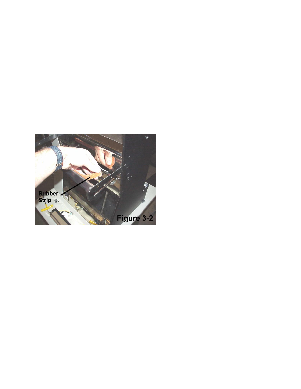
2. Remove the worn rubber pad by pulling from the end corner of the rubber strip. Once started, the
rubber will easily slide out from the metal pressure strip housing. See Figure 3-2.
3. Clean out the metal slot with alcohol and a cloth or brush.
4. Slide the extruded rubber into the metal housing slot starting at one end and continuing to work the
rubber along the length of the slot. When into position, the rubber strip should be loose in the slot.
Caution! Metal housing for rubber strip has sharp corners and sharp edges. When rubber is
removed, carefully cleat slot with thick cloth not allowing contact with fingers or hands.
3.3 PTFE Anti-Stick Advancement
PTFE Anti-Stick will wear with continued use and prematurely tear if contacting the product when
sealing. If the material wears or tears affecting the seals, it can be advanced to bring new material in the
seal area. To advance the material, insert a small flathead (common) screwdriver into the bottom 1/4”
hole located on the right-side panel of the unit. When you feel the screwdriver enter into the slot of the
rod, turn the screwdriver counterclockwise to advance new material into position.
After turning new material into position, turn the rod clockwise slightly so that there is very little tension
on the sheet.
Note: If the sheet is too tight (too much tension), the material may tear during the seal operation.
Caution! the following maintenance procedures should only be performed by trained and
qualified maintenance technicians.
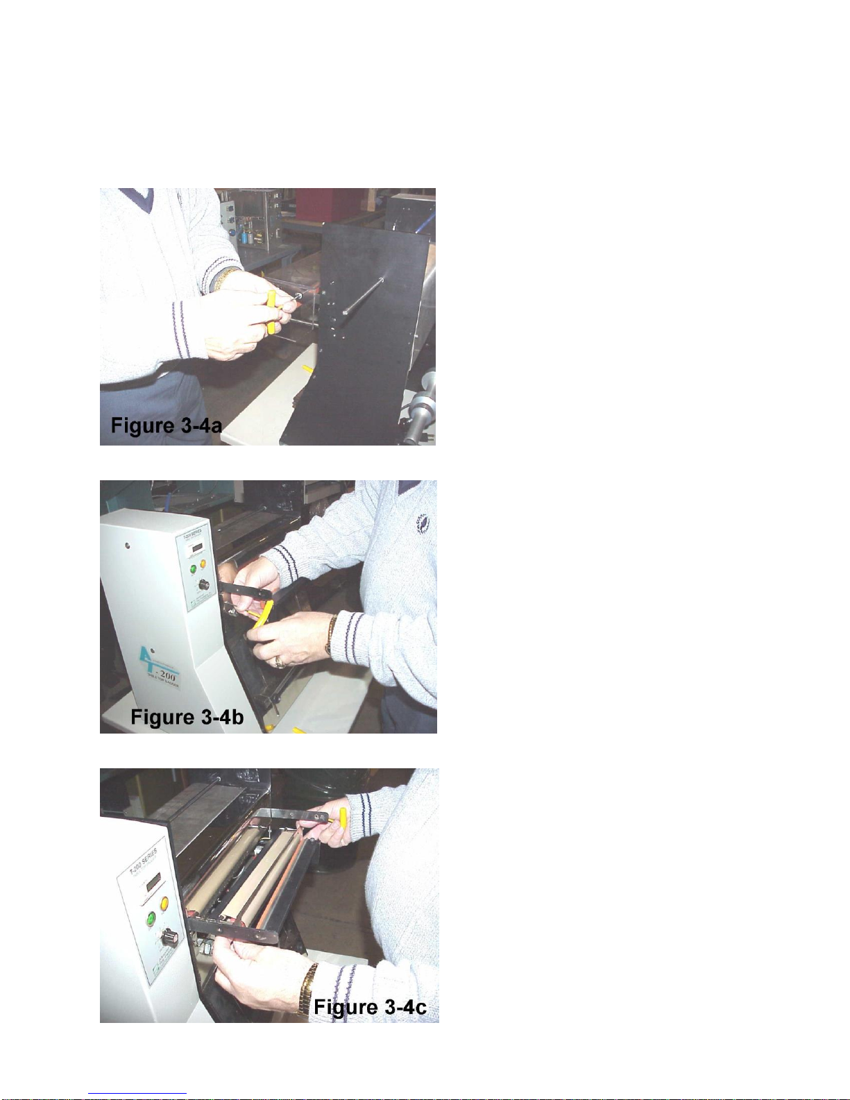
3.4 PTFE Anti-Stick Sheet Replacement
When the PTFE Anti-Stick sheet has been exhausted, it will become loose from the upper rod and will
require replacement. To replace the PTFE Anti-Stick Sheet, follow these procedures: (See Figures 3-4a
through 3-4d)

1. Remove air from the unit, turn the T-200 power “OFF” and unplug the power cord.
2. Lift the funnel assembly and top cover upward.
3. Remove four screws from the guard assembly and remove the Lexan guard.
4. Allow the sealer mechanism to cool for at least 15 minutes.
5. Remove the two screws located on the right and left side of the seal bar which hold the seal assembly
mechanism in place.
6. Pull one side (right or left side) of the seal assembly out from the front plate. Since the seal assembly
is tight, some maneuvering may be required to remove the assembly from the machine. To avoid damage
to components or wiring, do not force the assembly.
7. Disconnect the two wire connectors and remove the complete assembly.
8. Unclip the springs from the rods and remove the upper rod.
9. Attach a new sheet of PTFE Anti-Stick material to the upper rod so that the sheet end is parallel. Wind
the material onto the upper rod ensuring that it is evenly and tightly wound.
10. Reinstall the upper rod and thread the material ensuring that the material wraps around the spring
loaded “U” channel.
11. Reattach the material to the lower rod and install the springs in the grooves on the rods.
12. Turn the material at least two wraps onto the bottom rod.
13. Reconnect the wire connectors and install the heater bar ensuring that the full rod is positioned at the
top. Secure seal assembly with two screws and mount guard.
3.5 Heater Element Replacement
Since the heater element is a normal wear item, it will require replacement when burned out, worn or
damaged. Heater element and heater bar life span may be increased by timely adjustment of the material,
avoiding an exposed element. Additionally, contact with the product may prematurely wear or damage
the heater element. The heater bar element is a thin strip of nichrome fastened across the length of heater
bar. If this element burns completely through itself or is damaged causing loss of continuity across the
element, the element must be replaced. Follow these procedures to replace the element:
1. Remove air from the unit, turn the T-200 power “OFF” and unplug the power cord.
2. Lift the funnel assembly and top cover upward.
3. Remove four screws from the guard assembly and remove the Lexan guard.
4. Allow the sealer mechanism to cool for at least 15 minutes.
5. Remove the two screws located on the right and left side of the seal bar which hold the seal assembly
mechanism in place.
6. Pull one side (right or left side) of the seal assembly out from the front plate. Since the seal assembly
is tight, some maneuvering may be required to remove the assembly from the machine. To avoid damage
to components or wiring, do not force the assembly.

7. Disconnect the two wire connectors and remove the complete assembly.
8. Wind all of the material onto the upper rod and disconnect from the lower rod.
9. Unclip the springs from the rods and remove both rods.
10. There are two screws on each side of the assembly, adjacent to the rod ends. Remove these screws to
allow the front place housing to be detached from the heater bar.
11. Disconnect the wires from the heater element and remove the two screws (one on each end) from the
ends of the heater bar that hold both the element and connectors in position.
12. Ensuring that the heater connectors are “aimed” away from the element, reattach the new nichrome
strip bending at the corners of the heater bar. Ensure that the nichrome is pulled tight before tightening
the screws on either end of the heater bar. You may be required to cut off excess nichrome wire.
13. Reattach the wire connectors to the heater element at each end of the heater bar.
14. Reattach the heater bar to the front plate assembly with four screws.
15. Reinstall the rods and re-thread the PTFE Anti-Stick around the spring loaded “U” Anti-Stick Shield
and reattach the PTFE Anti-Stick sheet to the upper rod so that the sheet end is parallel. Wind the PTFE
Anti-Stick onto the upper rod ensuring that it is evenly and tightly wound.
16. Reattach the springs in the grooves on the rods.
17. Turn the PTFE Anti-Stick Sheet at least two wraps onto the bottom rod.
18. Reconnect the wire connectors and install the heater bar ensuring that the full rod is positioned at the
top. Secure seal assembly with two screws and mount guard.
19. Prior to turning on power and sealing, ensure that the nichrome wire is flat against the heater bar and
pull tight across the bar so that there are no gaps between the nichrome wire and the heater bar.
screws.
3.6 Description of Anti-jam Circuit
The anti-jam mechanism decreases the possibility of damage to the T-200 if product or other objects are
in the seal area. The operation of the anti-jam circuit should be tested prior to production on a daily basis.
To test the anti-jam circuit, see Chapter 2, Section 2.4.
Although the anti-jam unit may also prevent or decrease the opportunity for injuries during the sealing or
heating operation, the anti-jam is not designed as a safety device. If not adjusted properly, damage may
result from obstructions in the seal area or personal injury may result from fingers or hands being in the
seal area when sealing.
If properly adjusted, a jam is detected when: 1) the rubber pressure strip does not contact the PTFE Anti-
Stick material at one or both sides of the Anti-Stick Shield or 2) the spring-loaded Anti-Stick Shield is
pressed prior to the rubber pressure strip contacting the Anti-Stick Shield.
If these conditions are met, the pressure seal bar will retract and heat will not be applied to the heater
element.
The anti-jam mechanism consists of: 1) two cylinder magnetic switches which detects the cylinder
position and 2) two magnetic sensors that detect the spring-loaded Anti-Stick Shield “U” channel
position.
3.7 Anti-jam Adjustments / Testing
If the anti-jam circuit is not functioning properly, following these procedures to test and/or adjust the anti-
jam components:
Test 1 Failed: Pressure bar does not retract when an obstruction of at least 1/4” in thickness is present
anywhere in the seal area. Follow these procedures to adjust and test the circuit:
1. Remove air from the unit, turn the T-200 power “OFF” and unplug the power cord.
2. Remove the back (stainless) cover and side (painted) cover.

3. Using a Multimeter set to “OHMS” Scale, place meter on Pins 3 and 5, Connector J3, Logic Control
Printed Circuit Board. Note: Pin 1 is the leftmost pin on Connector J3.
4. Manually push pressure bar inward until rubber strip slightly touches the Anti-Stick Shield evenly
across the pressure bar.
5. Loosen magnetic sensor collar located on the right seal cylinder. Adjust the magnetic sensor by sliding
it along the cylinder until the meter LED is illuminated.
6. Tighten magnetic sensor collar ensuring that LED is continually illuminated.
7. Then place meter on Pins 4 and 5, Connector J3, Logic Control Printed Circuit Board.
8. Complete steps 4 through 6 for the left seal cylinder.
9. Manually pull pressure bar out and then push inward alternating meter from pins 3 and 5 to pints 4 and
5 testing to see if the meter LED is illuminated when the pressure bar contacts the Anti-Stick Shield.
10. Replace all covers, apply air and power and test cycle as described in Chapter 2, Section 2.4, Test 1
to ensure proper operation.
Test 2 Failed: Pressure bar begins to move inward when an obstruction is present or when an object is
pressing inward on the Anti-Stick Shield.
1. Remove air from the unit, turn the T-200 power “OFF” and unplug the power cord.
2. Remove the back (stainless) cover and side (painted) cover.
3. Using a Multimeter set to “OHMS” Scale, place meter on Pins 1 and 2, Connector J3, Logic Control
Printed Circuit Board. Note: Pin 1 is the leftmost pin on Connector J3.
4. Manually push pressure bar inward until rubber strip slightly touches the Anti-Stick Shield evenly
across the pressure bar.
5. Then continue pressing inward on the right side of the pressure bar which will press the spring-loaded
Anti-Stick Shield inward.
6. Continuity should be present when the right side of the pressure bar is pushed inward, pressing the
Anti-Stick Shield inward. If no continuity is read, adjust the magnetic switch located on the rear
mounting bar on the heater bar assembly (See Dwg No T3-00161, Items 1-Rear Mounting Bar and 19-
Magnetic Switches). Secure locking nuts on magnetic switch when properly adjusted.
7. Repeat steps 3 through 6 for the left side of the pressure bar.
8. Manually pull pressure bar out and then push inward alternating between pushing in the right and left
sides of the Anti-Stick Shield ensuring there is continuity when the Anti-Stick Shield is pushed inward.
9. Replace all covers, apply air and power and test cycle as described in Chapter 2, Section 2.4, Test 2 to
ensure proper operation.
3.8 Preventative Maintenance
The following maintenance items should be performed by the operator or maintenance personnel to
prolong the life of the equipment. Failure to perform these tasks may result in premature wear, personal
injury, or equipment damage.
Item: Description: Frequency:
Anti-jam Test anti-jam prior to production Daily
Pressure Check air pressure to ensure 40-50psi Daily
PTFE Inspect for wear / holes / exposed nichrome Daily
Rubber Strip Clean rubber strip with alcohol Weekly or as required
Nichrome Wire Inspect for wear / damage. Tighten when Weekly
loose.
Cylinders Remove air and push in manually to ensure Weekly
free movement with no binding
Springs Inspect for cracks in springs, ensure free Monthly
movement
Wiring Ensure no loose contacts or worn shielding Monthly
Fasteners Tighten mounting bolts and fasteners Monthly


Chapter 4
Parts Identification
Recommended Spare Parts
Parts / Component Identification
Pneumatic Diagram
Wiring Diagram / Electronics

4.1 Recommended Spare Parts List
The following spare parts are recommended for your inventory which include components which can
easily be replaced. These items are either wear items or other components which may fail during the day
to day operation of the machine.
Level 1 Spare Parts Kit
Part Number Description Qty per assembly
TP-T8MA00140 Seal Bar Rubber Strip 1
TP-T8MA00109 Rubber Strip Holder 1
TP-T8MA00130 PTFE Anti-Stick Sheet 1
TP-T8MA00123 Heater Bar 1
TP-213303 Nichrome Wire 14”
TP-108154 Compression Springs 2
TP-406181 4 Micron Filter 1
TP-112300 Rubber Feet 4
TP-214215 O-Rings 5
TP-402176 Solenoid Valve 2
TP-403124 Pneumatic Cylinders 2
TP-215200 Magnetic Switch 2
TP-215019 Totalizing Counter 1
TP-219428 Logic Control PCB 1
4.2 Parts / Component Identification
This section includes assembly drawings of the T-200. Please use APPI part numbers whenever possible
to order replacement parts. You can also refer to Drawing Numbers and Corresponding Item Numbers on
the drawings to assist in determining the required components.
Assembly Number: TA-T80160-1 Major Assemblies & Parts (Refer to Dwg #T3-00160-1)
Item: Part Number: Description: Qty per assembly:
1 TA-T80103 Heater Bar Assembly 1
2 TA-T80162 Blower & Funnel Assy 1
3 TA-T80163 Pressure Bar Assembly 1
4 TP-T8MA00100 Front Cover 1
5 TP-T8MA00101 Side Cover 1
6 TP-T8MA00118 Sealer Block 2
7 TP-T8MA00126 Load Shelf 1
8 TP-T8MA00128 Guard Mount 1
9 TP-T8MA00129 Lexan Guard 1
10 TP-109152 Knob, Fluted 1/4-20 x ½ 2
11 TP-109213 Knob, Torque 10-32 x ½ 2
12 TP-109214 Knob, Instrument T-200 1
13 TP-201383 Potentiometer 500k 1
14 TP-204011 Neon LED Green 125V L5003 1
15 TP-204241 Neon LED (125v amber) 1
16 TP-215019 Counter, Electronic 1
Other manuals for T-200
1
Table of contents
Other Advanced Poly-Packaging Food Saver manuals


