Advanced Poly-Packaging T-200 User manual

T-200™ Advanced Poly
Table Top Bagger/Sealer
Operation Guide, Version 3
Setup, Operation and Parts Manual

Acknowledgments
Written By: Annie Braddock
Reviewed By: Stuart Baker
Copyright
2015 (Ver. 3),Copyright 2/2000 Advanced Poly-Packaging, Inc. (APPI). All rights reserved.
This manual and the program operating the equipment described in it are copyrighted. You may not copy this manual in whole or
part without the consent of Advanced Poly-Packaging, Inc.
All information pertaining to the promotion, sale, distribution, operation and maintenance of the T-200™ Advanced Poly
Tabletop Bagger / Sealer including this manual, drawings, schematic, wiring diagrams, videos, brochures, specification sheets,
figures, charts, or any other information, due to its proprietary design and manufacture remain the property of Advanced Poly
Packaging, Inc. Unauthorized duplication, distribution or disclosure to third parties without the expresses permission of
Advanced Poly-Packaging, Inc. is strictly prohibited.
Trademarks
T-200™ Table Top Bagger/Sealer is a trademark of Advanced Poly-Packaging, Inc. Advanced Poly-Packaging, Inc. owns also
the following trademarks: Advanced Poly-Bags, Advanced Poly-Bagger, Seal-a-Print, Roll-a-Print, Twin-Seal, Teflon Shield,
Advanced Poly-Pack, Advanced Poly-Bag, Advanced Bag.
Limited Warranty and Disclaimer
Warranty period is 12 months or 1,000,000 cycles whichever comes first. The warranty commences on the date of delivery of the
equipment to the Purchaser. APPI warrants to the Purchaser that the equipment is free from defects in workmanship or material
under normal use and service. During the warranty period, APPI agrees to repair or replace, at its sole option, without charge to
Purchaser, any defective component part of the equipment. To obtain service, Purchaser must return the equipment or component
to APPI or an authorized APPI distributor or service representative in an adequate container for shipping. Any shipping charges,
insurance, or other fees must be paid by Purchaser and all risk for the equipment shall remain with Purchaser until such time as
APPI takes receipt of the equipment. Upon receipt, APPI, the authorized distributor or service representative will promptly repair
or replace the defective component and then return the equipment or component to Purchaser, shipping charges, insurance and
additional fees prepaid. APPI may use reconditioned or like new parts or units, at its sole option, when repairing any component
or equipment. Repaired products shall carry the same amount of outstanding warranty as from original purchase. Any claim
under the warranty must include a dated proof of delivery. In any event, APPI's liability for defective components or equipment is
limited to repairing or replacing the components. This warranty is contingent upon proper use of the equipment by Purchaser and
does not cover: expendable component part such as Teflon, thermocouple wire, heater cartridge, rollers, bushings, and the like; or
if damage is due to accident, unusual physical, electrical or electromechanical stress, neglect, misuse, failure of electric power,
water damage (from airlines), improper environmental conditions, transportation, tampering with or altering of the equipment,
packaging of corrosive or contaminating products or other products damaging to components, and equipment or components not
owned or in the possession of original Purchaser. APPI will not be liable for loss of production, profits, lost savings, special,
incidental, consequential, indirect or other similar damages arising from breach of warranty, breach of contract, negligence, or
their legal action even if APPI or its agent has been advised of the possibility of such damages or for any claim brought against
the Purchaser by another party. This warranty allocates risks of equipment failure between Purchaser and APPI. APPI's pricing
reflects this allocation of risk and the limitations of liability contained in this warranty. The warranty set forth above is in lieu of
all other express warranties, whether oral or written. The agents, employees, distributors and dealers of APPI are not authorized
to make modifications to this warranty, or additional warranties binding on APPI. Accordingly, additional statements such as
dealer advertising or presentations, whether oral or written, do not constitute warranties by APPI and should not be relied upon.
Warranty on equipment is considered void when outstanding balances become delinquent (over 30 days late - 60 days after ship
date). Equipment Integration to other Equipment: APPI assumes no responsibility for the integration of its products to other
products or within a system unless APPI performs the integration, testing and provides the results of the tests to the purchaser in
writing. Furthermore, APPI assumes no responsibility for bag sizing whether suggested or recommended.
1

TABLE OF CONTENTS
Chapter 1: Getting Started 4
1.1 Welcome................................................................................................................................ 5
1.2 Overview............................................................................................................................... 5
1.3 Contact Information .............................................................................................................. 5
1.4 Using This Manual................................................................................................................ 5
1.5 Special Features of the T-200................................................................................................ 6
1.6 Available Options.................................................................................................................. 6
1.7 Special Note on Safety.......................................................................................................... 6
1.8 Specifications........................................................................................................................ 7
1.9 Unpacking & Setup............................................................................................................... 7
1.10 Operating Environment....................................................................................................... 7
1.11 Warranty Registration......................................................................................................... 8
Chapter 2: Getting Started & Equipment Operation 10
2.1 Air & Power Hookup .......................................................................................................... 11
2.2 Roll Mounting and Threading............................................................................................. 11
2.3 Main Power......................................................................................................................... 11
2.4 Operation / Component Test Prior to Production ............................................................... 11
2.5 Heat / Dwell Time Adjustment ........................................................................................... 11
2.6 Air / Seal Pressure Adjustments.......................................................................................... 12
2.7 Blower / Bag Opening......................................................................................................... 12
2.8 Funnel Position.................................................................................................................... 12
2.9 Sealing the Bag / Foot Switch or Guard Switch Operation ................................................ 12
2.10 Adjustable Shelf................................................................................................................ 13
2.11 Pull Tension Adjustments ................................................................................................. 13
2.12 Note on Seal Quality......................................................................................................... 13
2.13 Bag Counter / Counter Reset............................................................................................. 13
Chapter 3: Operation Adjustments / Replacement of Wear Items 16
3.1 Adding Teflon to Rubber Strip and Cleaning ..................................................................... 17
3.2 Rubber Strip Replacement .................................................................................................. 17
3.3 Teflon Advancement........................................................................................................... 18
3.4 Teflon Sheet Replacement .................................................................................................. 18
2

3.5 Heater Cartridge / Thermocouple Replacement.................................................................. 20
3.6 Description of Anti-jam Circuit .......................................................................................... 20
3.7 Anti-jam Adjustments / Testing.......................................................................................... 20
3.8 Preventative Maintenance ................................................................................................... 21
Chapter 4: Parts Identification 22
4.1 Recommended Spare Parts List .......................................................................................... 23
4.2 Parts / Component Identification......................................................................................... 23
4.3 Pneumatic Diagram............................................................................................................. 23
4.4 Wiring Diagram................................................................................................................... 23
A. T-200 System Layout..................................................................................................... 24
B. T-200 Electronics Assembly.......................................................................................... 25
C. T-200 Heater Bar Assembly........................................................................................... 27
D. T-200 Main Frame Assembly ........................................................................................29
E. T-200 Adjustable Chute Assembly................................................................................ 32
F. T-200 Pneumatic Layout................................................................................................ 33
G. T-200 Electrical Layout ................................................................................................. 34
3


1.1 Welcome
Thank you for selecting the T-200™ Series Table Top Bagger / Sealer. The T-200 is easy to operate and
quick to set up, making it ideal for long or short packaging runs. When labor reduction and fast
changeover are important, the Advanced Poly T-200™ Tabletop Bagger / Sealer provides a reliable
bagging solution by using pre-opened bags on rolls, manufactured by Advanced Poly-Packaging, Inc.
1.2 Overview
The T-200 is designed to package various industrial, medical, molded and food products. With bag sizes
that range from 2" x 3" to 11" x 16" and mil thickness from 1 mil to 4 mil, the T-200 will demonstrate to
be a versatile bagger.
The T-200 is designed to lower your packaging costs with increased speeds, versatility, reliability, and
simplicity. Instead of sealing with a conventional jaw sealer, which requires the operator to pull bags out
and open them individually from a carton, the T-200™ Tabletop Bagger / Sealer removes this hassle by
feeding pre-opened bags through the bagger, allowing the operator to easily index the bag into position.
Once loaded, the bag can be sealed without having to separate the bag at the perforation. Ideal for
numerous short runs with virtually no production loss for job changeovers since all that is required is a
roll change. Single knob heat, dwell and cool setting adjustments makes setups a snap.
1.3 Contact Information
To better serve your bagging needs, call (330) 785-4000 or toll free 1-(800) 754-4403 for convenient
service solutions, Monday through Thursday, 9:00 AM to 5:30 PM EST, or Friday 9:00 AM to 5:00 PM
EST. For technical assistance with current machinery, ask for Service. To order spare parts for your
system, ask for Parts. To order auxiliary equipment for your current system, ask for Machine Sales. To
place an order for bags, ask for Bag Sales.
You may also contact any of these departments by email:
Reach Service at Service@advancedpoly.com
Reach Parts at Parts@advancedpoly.com
Reach Machine Sales at MachineSales@advancedpoly.com
Reach Bag Sales at Bagsales@advancedpoly.com
For general inquires: Sales@advancedpoly.com
Or visit us online at www.advancedpoly.com
In order to provide the best service possible, please have model and serial number ready.
1.4 Using This Manual
The following manual conventions are frequently used to assist in understanding important information,
alerting the operator of potentially dangerous or damaging practices, and the normal functions of the T-
200 Sealer / Bagger.
Text normal text
Italics Used for emphasis
BOLDFACE Used to identify heading names
5

Note: Used to identify important information
CAUTION:Warning messages. To avoid physical harm, damage to equipment or damage to the product.
Be sure to read these messages carefully.
1.5 Special Features of the T-200
The T-200 has been designed with simplicity of operation and ease of maintenance in mind.
The totalizing counter counts cycles of operation and has a reset feature. Press the reset button at the
beginning of each shift or day to record packaging production.
Patented design seal assembly (Teflon Shield) - Teflon is only in contact with hot wire during sealing
and is then stripped away from the wire immediately after sealing; reduces contamination buildup,
increases Teflon life and improves seal integrity.
Double or triple seal quickly and easily - Seal the bag a second time or third time by pulling down and
sealing for consistent placement of seals.
Patented Anti-Jam Device -During the loading and sealing operation, this device detects obstructions and
automatically reverses the pressure bar, discontinuing the cycle operation.
1.6 Available Options
Spare Parts Kit: Additional Teflon, heater wire, valve and other components make this kit a must.
See Chapter 4, Section 4.l for recommended Spare Parts Kit.
Special funnels: Send us your product and we will evaluate the loading to determine the best funnel
design.
Bag deflator: Quickly mounts to the sealer bar squeezing the air from the bag while sealing.
1.7 Special Note on Safety
Many safety features have been included in the mechanical, electronic and pneumatic systems of this
machine. Despite these safety precautions, operators may receive lacerations, minor burns, or crushed or
broken bone injuries if they come in contact with any moving components. Improper use, improper
adjustment and neglect of preventative maintenance may result in serious personal injury. No special
personal protective equipment is required to operate the equipment, but eye protection, gloves or other
protection should be worn, depending on the characteristics of the product being packaged and the
method of loading the product.
Please carefully read the following precautions to operate the equipment properly and avoid injury:
General topics regarding safety:
•CAUTION:Never operate the machine with covers, guards or funnels removed
•CAUTION: Do not reach under the Lexan guard or into the seal area.
•CAUTION: Only certified maintenance or electrical personnel should perform maintenance
procedures.
•CAUTION: Standard tag/lockout procedures include disconnecting air and electricity when
performing maintenance tasks.
•CAUTION: Do not attempt to reprogram machine.
6

•CAUTION: Use only APPI approved parts/replacement components.
•CAUTION: Do not modify or otherwise alter machine operation, components or design.
Potential injuries:
•CAUTION: Cuts or minor abrasions from sharp objects, including not but limited to sheet
metal fingers, screws, edges
•CAUTION: Crush injuries from pinch points, including but not limited to bag rolls shaft,
pinch rollers, funnel assembly or seal area.
•CAUTION: Back, arm, leg or other muscle strain from lifting rolls of bags, boxes of bags or
product.
•CAUTION: Muscle strain from loading bags, separating bags or other repetitive functions
•CAUTION: Electrical shock if unit is not turned off and unplugged prior to removing guards
or covers
•CAUTION: Minor burns form exposure to heater bar
•CAUTION: Eye injury from not wearing eye protection during loading of product or sealing
of bags.
1.8 Specifications
Dimensions:
19.25” wide x 14.675” deep x 21” tall
Weight:
50 lbs.
Air:
50 psi
Electric:
115V/60Hz or 220V/50Hz
Bag sizes:
2 x 2 up to 11 x 16
Product pass through area:
approx. 2.75”
1.9 Unpacking & Setup
The T-200 is shipped completely assembled and in a carton. Remove all tape, banding or packing
materials that secure the machine. To ensure the highest production possible, consider product flow to the
bagger and packaged product flow away from the bagger when positioning the bagger into your
packaging areas.
1.10 Operating Environment
When you choose a location for installation, make sure the area is free of excess dust, dirt and moisture.
Operating room temperature should range from 50°F to 100°F (10°C to 87.77°C).
7

1.11 Warranty Registration
This section must be completed and returned to Advanced Poly Packaging, Inc. to register the T-200 for
Warranty Protection.
T-200 Serial Number:
(Serial number located on the back panel)
Company Name and Address Contact Name(s) / Title(s) / Phone Number
________________________________
________________________________
________________________________
________________________________________
________________________________________
________________________________________
Please fax or mail this page to:
Service Manager
Advanced Poly-Packaging, Inc.
1331 Emmitt Road
Akron, OH 44306
USA
Fax # (USA) 330-785-4010
Or email the information above to: service@advancedpoly.com
8

This page intentionally left blank.
9

Chapter 2: Getting Started & Equipment
Operation
Air & Power Hookup
Roll Mounting and Threading
Main Power
Operation / Component Test Prior to Production
Heat / Dwell Time Adjustment
Air / Seal Pressure Adjustments
Blower / Bag Opening
Funnel Position
Sealing the Bag / Foot Switch or Guard Switch Operation
Adjustable Shelf
Pull Tension Adjustments
Note on Seal Quality
Bag Counter / Counter Reset
10

2.1 Air & Power Hookup
The T-200 is equipped with an internal regulator and the air supply should be fed to the T-200 with ¼”
min. O.D. poly tubing. Make the connection at the rear of the sealer. Set the air pressure on the T-200
between 40 and 50 psi.
2.2 Roll Mounting and Threading
Loosen one of the knobs located on the chuck which secures the roll into position. Mount the roll of bags
onto the bag roll shaft and secure the bag roll into position with the chuck. With the loose web of bags
falling over the rear of the roll, insert the web into the slot above the stainless rear cover and below the
top cover. With the web of bags positioned under the top cover, raise the top cover of the T-200 by lifting
the funnel mounting rods. Pull the web forward through the cover while lowering the top cover. When
the top cover is lowered, the first bag should open by the airflow. The roll shaft is fixed into position
with a pin and will not spin. The roll spins on the fixed shaft. See Threading Diagram at the end of the
chapter, Figure 2-1.
2.3 Main Power
The power switch is located on the rear right lower side. In the ON or “up” position, the switch is
illuminated indicating that power is supplied to the unit.
2.4 Operation / Component Test Prior to Production
Prior to beginning production, the anti-jam mechanism should be tested by following these procedures:
Test 1: With air applied and the power on, position an object over 1/4” in thickness (a pen or pencil for
example) on the far left side of the seal bar with the object in contact with the Teflon Sheet, but not
pressing in the spring-loaded “U” channel. Press the footswitch. The Anti-jam circuit is working
properly if the pressure bar retracts and immediately releases. If the pressure bar does not immediately
retract, do not begin production and refer to Chapter 3, Section 3.6 for description of Anti-jam circuit.
Test 2: With air applied and the power on, position an object over 1/4” in thickness (a pen or pencil for
example) on the far left side of the seal bar with the object pushing inward on the Teflon Sheet. Ensure
that you are pressing in the spring-loaded “U” channel Teflon Shield and then press the footswitch. The
Anti-jam circuit is working properly if the pressure bar does NOT move inward. If the pressure moves
inward, do not begin production and refer to Chapter 3, Section 3.6 for instruction on Anti-jam
Adjustments.
Continue these test procedures with the object being moved along the entire seal area length from the left
to the right side of the seal area.
2.5 Heat / Dwell Time Adjustment
The T-200 uses a heater cartridge to supply constant heat to the heater bar. The temperature controller
maintains the set sealing temperature after a minimal initial phase when the T-200 is first powered on and
the temperature will climb and then settle into the set temperature.
The duration of time that the sealer bar is against the plate can be adjusted using the two buttons marked
Seal Time and Cool Time. Tapping the Seal Time button will increase the amount of time used to create
the seal while tapping the Cool Time button will decrease the amount of time used to create the seal.
11

Note: If the sealer bar touches the front of the machine, and immediately reverses, this is an Anti-Jam
condition. Something is obstructing the sealing area, the main air pressure is too low, or the Anti-Jam
sensors need adjusted.
Note: Excessive seal time can cause burns in the Teflon sheet and the bag and decrease the life of the
heater bar.
CAUTION: THE SEAL BAR IS HOT! DO NOT PLACE FINGERS IN THE SEALING AREA.
2.6 Air / Seal Pressure Adjustments
To obtain good consistent seals, air pressure must be adjusted. The pressure valve is located on the rear
of the unit. Typically, the air pressure is set to a constant pressure of 40 to 50 psi. To increase the
pressure, pull the black knob outward, away from the machine and then turn clockwise; then push to knob
inward to lock into position. To decrease pressure, pull the knob outward, turn clockwise and press the
knob inward.
2.7 Blower / Bag Opening
The T-200 Sealer/Bagger is equipped with a 6” wide air knife and flow control valve to ensure that the
bags blow open quickly and consistently. Since the air knife speeds up air, compressed air is conserved.
Adjust the volume of air with the Blower flow control valve located on the rear of the unit (bronze knob).
To slow or reduce the volume of air, turn the knob counterclockwise; to increase the air flow, turn the
knob clockwise. Begin by turning the blower all the way down and increase slightly until the bags blow
open continuously and consistently. Once adjusted, there is a locking nut to prohibit the knob from
loosening.
Note: Excessive air flow can cause the bag to move around and product to possibly spill from the bag.
2.8 Funnel Position
The funnel can be tilted in or out and adjusted closer or further from the bag opening. Typically, the
bottom of the funnel is positioned approximately ½” from top of the bag opening. The funnel bracket
assembly can be pushed inward, closer to the bag dependent upon production dimensions.
Note: If the funnel is too close to the front plate, air flow may be blocked causing the bag not to blow
open.
CAUTION: To avoid personal injury, do not operate the T-200 without guards, covers and funnel in
position.
2.9 Sealing the Bag / Foot Switch or Guard Switch Operation
Carefully pull the bag downward into the sealing position and load the product by allowing the product to
slide down the funnel.
Once the product is in the bag, the bag can be sealed or left unsealed.
To start the seal operation of the bagger, the operator has two options: 1) footswitch operation or 2) guard
switch operation, described as follows:
1) Foot switch operation: when the footswitch is plugged into the back of the bagger, pressing the
footswitch will begin the operation of the sealer mechanism. The guard switch is disabled when the
footswitch is plugged in.
12

2) Guard Switch operation: to operate the seal
mechanism using the guard switch, the
footswitch must be unplugged and a “key” must
be inserted into the footswitch plug located at
the rear of the unit. When the key is plugged in,
the guard switch may be used to cycle the
machine. With the key in position and the
product is in the bag and the bag is in the
desired seal position, press downward on the
front center of the guard to begin the seal
operation. The guard is spring-loaded with a
micro switch mounted inside the panel (See Fig.
2-9).
CAUTION: Ensure your fingers are not in the seal area when pressing the footswitch or guard switch
or your fingers may be pinched or burned by the closing seal bar. Once the bag is sealed, pull
downward until the next empty bag is in the seal position, load the bag and continue the seal process.
2.10 Adjustable Shelf
The T-200 bagger is equipped with an adjustable support shelf which has two functions: 1) assists the
operator with seal position by allowing the operator to pull the bottom of the bag down to the shelf,
2) Supports heavier products when dropped into the bag. The shelf can be adjusted up and down by
loosening both thumb screws and sliding the shelf up and down, ensuring the shelf is level.
2.11 Pull Tension Adjustments
Since perforation strength is determined by bag width and thickness, pull tension adjustments may be
required to avoid bags separating or prematurely tearing at the perforation.
If the bag perforation tears prematurely while pulling the bag downward into the seal position, adjust the
tension of the film by 1) sliding one or more of the rubber grommets which are located on the front roller
in the top cover left or right, out of contact with the bag 2) loosening the roll chucks that contact the bag
roll core plugs.
If the roll unwinds or excess slack is in the web while pulling the bags into position, you may increase
tension by 1) sliding the rubber grommets toward the center of the roller and in contact with the bag or 2)
pushing the roll chuck inward, applying pressure to the core plugs and then tightening the thumb knob
screws that secure the roll chucks into position on the roll shaft.
2.12 Note on Seal Quality
After sealing the first bag and allowing the seal to cool, test the seal for strength by attempting to pull the
layers apart. Heat, dwell time and pressure affect the quality of seals. If the seal separates, increase the
seal time in small increments. Additionally, check the air pressure and increase the pressure in small
increments. After initial startup and after sealing several bags, you may decrease the dwell time slightly.
2.13 Bag Counter / Counter Reset
The T-200 Sealer/Bagger is equipped with a totalizing counter to count finished bags (counts seal
operations). Since seal operations are counted, any defective bags must be deducted from the count to
determine your production. A slide / locking switch is located on the counter which resets the count to
zero and then locks into position. Note: Since the counter is battery operated, the count will be
displayed when the power is turned off.
13

T-200 Threading Diagram
Figure 2-1
14

This page intentionally left blank.
15

Chapter 3: Operation Adjustments /
Replacement of Wear Items
Adding Teflon to Rubber Strip and Cleaning
Rubber Strip Replacement
Teflon Advancement
Teflon Sheet Replacement
Heater Cartridge / Thermocouple Replacement
Description of Anti-jam Circuit
Anti-jam Adjustments / Testing
Preventative Maintenance
16
3.1 Adding Teflon to Rubber Strip and Cleaning
New rubber is often sticky when initially used causing bags to cling to the rubber when sealed. But after
a short period, the rubber will become slick and not cling to the bag material. Self-adhesive Teflon strips
may be added to the rubber pressure strip if the product continually sticks to the rubber strip or to improve
seal integrity. Periodically clean the rubber strip with alcohol to remove contaminants and plastic
buildup.
3.2 Rubber Strip Replacement
Through normal use, the rubber strip will wear causing seal quality problems. The rubber will also wear
prematurely if contacting the product during the seal operation. When the wear affects the seal quality,
replace the rubber strip by following these procedures:
1. Remove air from the unit, turn the T-200
power “OFF” and unplug the power cord.
2. Remove Lexan Cover.
3. Remove the screws holding the Pressure
Bar to the Seal Blocks to take the rubber
strip holder out. Note: Keep hardware in
safe place to reuse later.
4. Remove the worn rubber pad by pulling
from the end corner of the rubber strip.
Once started, the rubber will easily slide
out from the metal pressure strip housing.
See Figure 3-1.
5. Clean out the metal slot with alcohol and
a cloth or brush.
6. Slide the extruded rubber into the metal
housing slot starting at one end and
continuing to work the rubber along the
length of the slot. When into position,
the rubber strip should be loose in the
slot.
CAUTION: Metal housing for rubber strip has sharp corners and sharp edges. When rubber is
removed, carefully clean slot with thick cloth not allowing contact with fingers or hands.
7. Reattach the Rubber strip holder back to the Seal Blocks using the same hardware from before.
Rubber Strip
Figure 3-1
17

3.3 Teflon Advancement
Teflon will wear with continued use and prematurely tear if contacting the product when sealing. If the
Teflon wears or tears affecting the seals, the Teflon can be advanced to bring new Teflon into the seal
area. To advance the Teflon, insert a small flathead (common) screwdriver into the bottom 1/4” hole
located on the right side panel of the unit. When you feel the screwdriver enter into the slot of the Teflon
rod, turn the screwdriver counterclockwise to advance new Teflon into position.
After turning new Teflon into position, turn the rod clockwise slightly so that there is very little tension
on the Teflon sheet.
Note: Teflon that is too tight will cause Anti-Jam issues and may also cause the Teflon to tear.
CAUTION: The following maintenance procedures should only be performed by trained and qualified
maintenance technicians.
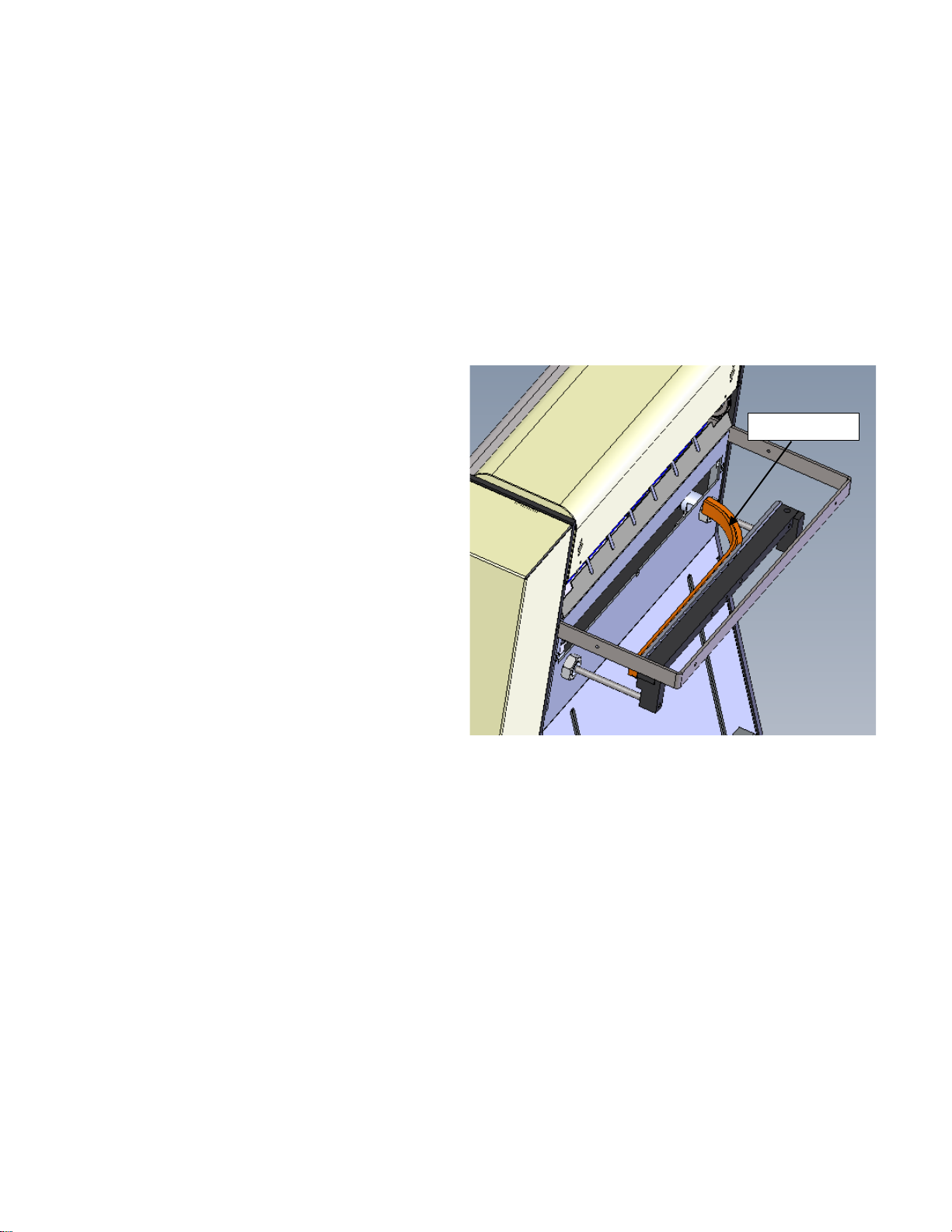
3.4 Teflon Sheet Replacement
When the Teflon sheet has been exhausted, it will become loose from the upper Teflon rod and will
require replacement. There are three phases when replacing the Teflon, Phase 1: Disassembling parts of
the machine to get to the Teflon Bracket, Phase 2: Changing the Teflon, and Phase 3: Reassembling the
machine parts taken off to get to the bracket. Use Figure 3-2,
Figure 3-3, and the T-200 Heater Bar Assembly Diagram in 4.2C with the following instructions. Call
APPI Service (800)754-4403 if additional help is needed.
Phase 1:
1. Remove air from the unit, turn the T-200 power “OFF” and unplug the power cord.
2. Remove Stainless Steel Cover from back of machine.
3. Lift the funnel assembly and top cover upward.
4. Remove four screws from the guard assembly and remove the Lexan guard, see Figure 3-2.
5. Allow the sealer mechanism to cool for at least 30 minutes.
Lift Up
Figure 3-2
18

6. Remove the two shoulder bolts form the pressure bar (
7.
8. Figure 3-3).
9. Remove the Pressure bar and turn down the black pressure bar blocks (
10.
11. Figure 3-3).
12. Remove the two screws located on the right and left side of the seal bar which hold the seal assembly
mechanism in place (
13.
14. Figure 3-3).
15. From the back, unplug the left and right side Anti-Jam Sensors, disconnect the Thermal-Couple, and
the left and right Heater Cartridge connectors.
16. From the front, pull one side (right or left side) of the seal assembly out from the front plate. Since the
seal assembly is tight, some maneuvering may be required to remove the assembly from the machine,
see To avoid damage to components or wiring, do not force the assembly.
Phase 2: (Refer to Heater Bar Assembly Diagram in 4.2B)
17. Remove the two springs (Item 14, TP-102153) holding the shafts together.
18. Remove the Socket Head Bolt and Nut on Each side of the Heater Plate.
19. Remove Teflon Shafts and Teflon Sheet.
20. Clean the adhesive from both shafts.
21. Separate the two shafts.
22. Lay one Shaft on the top of the Teflon Sheet and measure from the edge of the Teflon Sheet to the
edge of the Shaft. Ensure the Teflon Sheet is in the center of the Shaft.
23. Wrap a piece of tape on the Shaft at the edge of the Teflon.
24. Take the second Shaft, lay the first Shaft next to it and wrap tape around the end of the second Shaft
in exactly the same place as the first. Keep the taped ends on the same side of the Teflon Sheet.
25. Remove the adhesive backing from one end of the Teflon Sheet.
26. Align one Shaft parallel to the Teflon Sheet with the taped end of the Shaft meeting up with the edge
of the Teflon Sheet. Once the shaft is in position, lower onto adhesive side of the Teflon Sheet.
27. Roll the Shaft until you reach the end of the adhesive part.
28. Repeat with the other Shaft, ensuring the taped ends are on the same side. Once the Teflon Sheet has
been rolled over the Shafts, the tape may be removed.
29. Lay Heater Plate on a flat surface so the side plates stick up. Lay Teflon sheet over the Heater Plate
so that the shafts are parallel to the plate and the Teflon will roll on the outside of the shaft when
reattached.
Figure 3-3
8
8
6
6
7. Pressure Bar
7. Pressure Bar Block
7. Pressure Bar Block
19
Other manuals for T-200
1
Table of contents
Other Advanced Poly-Packaging Food Saver manuals


