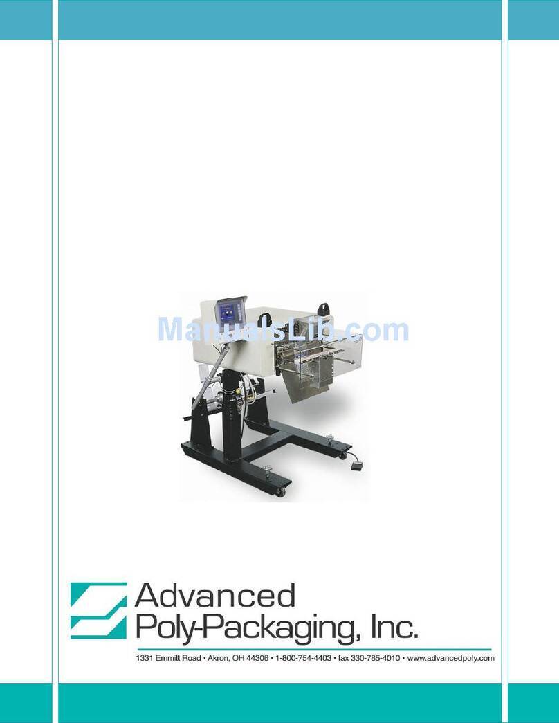
Advanced Poly-Packaging Advanced Poly-Bagger T-1000 User manual

T-1000
Advanced Poly-Bagger
______________________________________________________________________________
Operation Guide
Setup, Operation and Parts Manual (Version 2)


T-1000
Advanced Poly-Bagger
______________________________________________________________________________
Operation Guide
Setup, Operation and Parts Manual
1
Advanced
Poly-Packaging, Inc.
1331 Emmitt Road, Akron, Ohio 44306
Phone (800) 754-4403 Fax (330) 785-4010

Acknowledgments
Manual written by: Stuart Baker
Drawings by: Melody Cacho
Copyright
1995, 2001, Advanced Poly-Packaging, Inc. (APPI). All rights reserved.
This manual and the program operating the equipment described in it are copyrighted. You may not copy this manual in whole
or part without the consent of Advanced Poly-Packaging, Inc.
All information pertaining to the promotion, sale, distribution, operation, and maintenance of the T-1000 ADVANCED
POLY-BAGGER including this manual, drawings, schematic, wiring diagrams, VHF video tapes, brochures, specification
sheets, figures, charts, or any other information, due to its proprietary design and manufacture remain the property of Advanced
Poly Packaging, Inc. Unauthorized duplication, distribution, or disclosure to third parties without the expresses permission of
Advanced Poly-Packaging, Inc. is strictly prohibited.
Trademarks
T-1000 Advanced Poly-Bagger is a trademark of Advanced Poly-Packaging, Inc. Advanced Poly-Packaging, Inc. owns also the
following trademarks: Advanced Poly-Bags, Twin-Seal, Advanced Poly-Pack, Advanced Poly-Bag, Blist-a-Bag.
Limited Warranty & Disclaimer
Warranty period is 12 months or 1,000,000 cycles whichever comes first. The warranty commences on the date of delivery of
the equipment to the Purchaser.
APPI warrants to the Purchaser that the equipment is free from defects in workmanship or material under normal use and service.
During the warranty period, APPI agrees to repair or replace, at its sole option, without charge to Purchaser, any defective
component part of the equipment. To obtain service, Purchaser must return the equipment or component to APPI or an
authorized APPI distributor or service representative in an adequate container for shipping. Any shipping charges, insurance, or
other fees must be paid by Purchaser and all risk for the equipment shall remain with Purchaser until such time as APPI takes
receipt of the equipment. Upon receipt, APPI, the authorized distributor or service representative will promptly repair or replace
the defective component and then return the equipment or component to Purchaser, shipping charges, insurance and additional
fees prepaid. APPI may use reconditioned or like new parts or units, at its sole option, when repairing any component or
equipment. Repaired products shall carry the same amount of outstanding warranty as from original purchase. Any claim under
the warranty must include a dated proof of delivery. In any event, APPI's liability for defective components or equipment is
limited to repairing or replacing the components.
This warranty is contingent upon proper use of the equipment by Purchaser and does not cover: expendable component part such
as rollers, bushings, and the like; or if damage is due to accident, unusual physical, electrical, or electromechanical s tress,
neglect, misuse, failure of electric power, improper environmental conditions, transportation, tampering with or altering of the
equipment, packaging of corrosive or contaminating products or other products damaging to components, and equipment or
components not owned or in the possession of original Purchaser.
APPI will not be liable for loss of production, profits, lost savings, special, incidental, consequential, indirect, or other similar
damages arising from breach of warranty, breach of contract, negligence, or their legal action even if APPI or its agent has been
advised of the possibility of such damages or for any claim brought against the Purchaser by another party.
This warranty allocates risks of equipment failure between Purchaser and APPI. APPI's pricing reflects this allocation of risk
and the limitations of liability contained in this warranty. The warranty set forth above is in lieu of all other express warranties,
whether oral or written. The agents, employees, distributors, and dealers of APPI are not authorized to make modifications to
this warranty, or additional warranties binding on APPI. Accordingly, additional statements such as dealer advertising or
presentations, whether oral or written, do not constitute warranties by APPI and should not be relied upon.
Warranty on equipment is considered void when outstanding balances become delinquent (over 30 days late - 60 days after ship
date).
Equipment Integration to other Equipment: APPI assumes no responsibility for the integration of its products to other products
or within a system unless APPI performs the integration, testing and provides the results of the tests to the purchaser in writing.
Furthermore, APPI assumes no responsibility for bag sizing whether suggested or recommended.
2

Contents
______________________________________________________________________________
Chapter 1, Introduction
1.1 Welcome
1.2 Overview
1.3 Special Features
1.4 System Integration
1.5 Options Available
1.6 Using This Manual
1.7 Registration Information
Chapter 2, Getting Started
2.1 Installation Procedures
2.2 Air & Power Requirements
2.3 Assembly
2.4 Air & Power Hookup
2.5 Main Power
2.6 Bag Threading
2.7 Cycle Operation
2.8 Note on Adjustments
2.9 Energy Conservation & Component Saver
Chapter 3, Touch Screen Operation
3.1 Touch Screen Front Panel
3.2 Touch Screen Back Panel
3.3 Specifications
3.4 Contrast Adjustments
3.5 Touch Screen Program
3.6 Intro. Screen
3.7 Main Menu
3.8 Bag Setup Menu
3.9 Seal Time
3.10 Seal Temperature
3.11 Seal Point
3.12 Note on Seal Quality
3.13 Air Pulse
3.14 Blower
3.15 Fill Time
3.16 Counters
3.17 Options
3.18 Accumulating Funnel
3.19 Load Shelf
3.20 Inline Printer
3.21 Counting Funnel
3

3.22 Insert Funnel
3.23 Diverting Funnel
3.24 Palm Buttons
3.25 Light Curtain
3.26 Trim Seal
3.27 Flat Seal Assembly
3.28 Twin SealTM Assembly
3.29 Compartment Seal
3.30 Auxiliary Options Setup
3.31 Graphs Screen
3.32 Job Save / Recall
3.33 Technical Assistance
3.34 Timers
3.35 Passwords
3.36 Inputs / Outputs (PLC)
3.37 Input / Outputs (Expansion Card)
3.38 UF-5000 Operation Screen
3.39 UF-5000 Settings Screen
3.40 Information Screens
3.41 Message Screens
Chapter 4, Operation, Settings & Adjustments
4.1 Machine Adjustments
4.2 Tracking & Alignment
4.3 Compression (Nip) Roller Adjustment
4.4 Dancer Assembly
4.5 Dancer Bar & Brake Strap
4.6 Upper Roller Guides
4.7 PTFE Anti-Stick Adjustment
4.8 PTFE Anti-Stick Replacement
4.9 Pressure Bar Adjustment
4.10 Drive Belt Tension
4.11 Seal Cylinder Adjustment
4.12 Pressure Bar Rubber Replacement
4.13 Anti-jam Adjustment
4.14 Heater Cartridge Replacement
4.15 Thermocouple Wire Replacement
4.16 Brake Gap Adjustment
4.17 Battery Replacement
4.18 PLC E-Prom Installation Instructions
Chapter 5, Parts
5.1 Machine Assembly
5.2 Head Assembly
5.3 Flat Load Shelf Sub-Assembly
5.4 Main Frame Assembly
5.5 Main Frame Assembly
5.6 Inner Main Frame Assembly

5.7 Upper Roller Finger Assembly
5.8 Air Knife Assembly
5.9 Outer Main Frame Assembly
5.10 Pneumatics Mntg. Valve
5.11 Electrical Panel Assembly
5.12 Sealer Frame Assembly
5.13 Seal Frame Manifold Sub-Assembly
5.14 Pressure Bar Sub-Assembly
5.15 Heater Bar Sub-Assembly
5.16 PTFE Anti-Stick Guide Sub-Assembly
5.17 Grooved Roller Mounting Sub-Assembly
5.18 Bag Finger Grounding Assembly
5.19 Stand Assembly
5.20 Base Assembly
5.21 Upper Column Assembly
5.22 Dancer Assembly
5.23 Dancer Guide Sub-Assembly
5.24 Touch Screen Assembly
5.25 SP-10 Spare Parts Kit (Level 1)
5.26 SP-20 Spare Parts Kit
Chapter 6, Preventive Maintenance & Scheduled Maintenance
6.1 Preventative Maintenance & Schedule Maintenance
6.2 P.M. Checklist
6.3 Scheduled Maintenance Chart
Chapter 7, Trouble-Shooting
7.1 Trouble-shooting
7.2 Trouble-shooting Checklist
7.3 Interface PCB Voltage Table
7.4 Wiring Tab List
7.5 Circuit Boards
7.6 Pneumatic Valves / Cylinders
7.7 Wiring Diagram
7.8 Notes
5

This page intentionally left blank.
6

Operation Guide
__________________________________________________________________
Chapter 1, Introduction
Welcome
Overview
Special Features
System Integration
Options Available
Using This Manual
Registration Information
7

1.1 Introduction
Now that you've decided to upgrade your packaging facilities with the T-1000 Advanced
Poly-Bagger from Advanced Poly-Packaging, Inc., we thank you for selecting our equipment,
materials and service. Where labor reduction and fast changeover is important, the T-1000 uses
Advanced Poly-Bags (pre-opened bags on rolls), manufactured by Advanced Poly-Packaging,
Inc. Extensively equipped with several "built-in", ready-to-use options, the T-1000 can package
various industrial, medical, molded and food products. With a wide range of bag sizes (2" x 3"
to 14" x 30") and mil thickness (1 mil to 5 mil), we hope the T-1000 will meet all of your
bagging needs.
1.2 Overview
The T-1000 ADVANCED POLY-BAGGERTM is a system designed to lower your packaging
costs with high speeds, versatility, reliability, and simplicity.
High Speeds - Indexes, opens, seals and tears off a bag at rates over 100 cycles per minute,
dependent upon bag size and product characteristics.
Versatility - Mobile on rugged castors for packaging at any production station throughout your
facility. Ideal for numerous short runs with virtually no production loss for job changeovers
since all that is required is a roll change and recalling the bag settings from memory.
Reliability - Crafted from the highest quality components and materials to withstand the most
rigorous manufacturing environment; sturdy mounts with castors, and rugged frame guarantee
long life and usefulness with minimal maintenance.
Simplicity - A "user-friendly" menu-driven touch screen program allows operators to setup the
bag, options and auxiliary equipment, save the settings in memory, and recall those settings for
repeat runs.
1.3 Special Features
Energy Conservation & Component Saver - To extend its life and conserve energy in
your plant, the T-1000 is programmed to sequentially shut components down when not in use for
extended periods. First, the motor will shut off until the foot switch is pressed or a signal is
received to initiate operation. Later, current to the heater bar will discontinue and place the
T-1000 in the stop mode. Shortly thereafter, air flow will be shut off preserving compressed air.
A screen saver is also provided.
Predetermined Counter - Preset the T-1000 to stop after a predetermined number of bags
have been packaged. Set the quantity of finished bags to complete a work order or fill a shipping
container. Once the work order is complete or the container is full, the T-1000 stops to alert the
operator to begin the next work order or to push aside the box to begin filling another. Pressing
anywhere on the screen resets the counter and starts the bagging operation with minimum delay.
Totalizing Counter - Reset this counter at the beginning of each shift or day to record
packaging production over a period of time.
8

Maintenance Counter/Chart - Periodically check this counter (total machine cycles) to
determine preventative maintenance / component inspection intervals for inspection /
maintenance criteria and intervals.
Continuous Strip Option - Leave bags connected in an "endless" strip or a predetermined
number of strips of sealed bags.
Networking Capability - Allows remote access to PLC for production and status reports.
Communications Port/Modem - Allows for auxiliary communications.
Anti-Jam Device - During the loading and sealing operation, this device will detect
obstructions and automatically reverse the pressure bar and discontinue the cycle operation.
Castors Assembly - Rugged castors are standard for plant mobility.
1.4 System Integration
The T-1000 is preprogrammed to integrate automatically to major brand vibratory counters and
feeders, weigh scales, volumetric fillers, auger fillers and infeed conveyors. As an OEM for
numerous equipment manufacturers of infeed systems, we can offer the best available system,
with the T-1000 Advanced Poly-Bagger as the integral packaging component.
FREE CONSULTATION AND PRODUCT EVALUATION: We invite you to call to discuss
your packaging requirements and our free product packaging analysis.
1.5 Additional Options Available
Although the T-1000 is extensively equipped with many "built-in" options described above,
various auxiliary options and equipment can easily be added for special purpose packaging. The
following options may be purchased from Advanced Poly-Packaging, Inc.
AF-10 Accumulating Funnel - Increase production by allowing a continuous infeed of
product into the funnel without regard for the operation of the T-1000. The Accumulating
Funnel will collect the product while the bag is sealing. Once another bag is in position and
blown open, the funnel discharges the product into the bag without stopping the flow of product
into the funnel.
BB-10 Bag Blow-off Assembly - Allows for faster packaging of lighter products by
stripping bags from seal bar. Also used when bags stick to PTFE Anti-Stick Sheet or seal bar.
BF-10 Bag Deflator (sponge or rubber loop) - Flattens package by removing air from bag
before sealing.
CF-10 Counting Funnel - Preprogrammed, the T-1000 Counting Funnel counts product
entering the funnel or bag and signals the T-1000 to seal the bag when the preset quantity has
been reached. The Counting Funnel may operate in conjunction with the Accumulating Funnel
for fully automatic operations.

DF-10 Diverting Funnel - Mounts to bagger beneath the seal bar or the end of a takeaway
conveyor to count bags into one of two boxes. When the final bag count is reached, a diverter
redirects from Box A to Box B.
FS-10 Flat Seal Assembly - Helps decrease / eliminate wrinkles in the seal by pulling sides
of bag. Increase bag integrity.
LS-10 Load / Support Shelf - Provides support for heavier packages when dropped into bag.
Sizes: 10", 15", or 20" long.
LSV-10 Load Shelf Vibrator Kit - Settles product to bottom of bag to increase volume of
product in bag. (LS-10 back plate required).
PB-20 Dual Palm Buttons - Decrease the possibility of injury to hands and fingers. Operator
must push two buttons simultaneously to actuate seal bar.
LC-10 Light Safety Curtain - Safety feature that prohibits seal operation when there are
obstructions in light screen. Also, toggle on the “auto cycle” feature and the seal bar
automatically activates when the light curtain field is unobstructed (trailing edge of signal).
Printpad Terminal & Scanner - No longer is a PC required to operate a thermal transfer
printer. Alphanumeric keypad with programmable function keys, printer controls, easy-to-read
display, scanned input, and stored databases. Data can be imported directly from external
devices such as scales or other test and measurement equipment. Designed for an industrial
environment, this compact unit is sealed for protection and costs less than most PCs.
TS-10 Trim Seal Assembly - Trims excess film from bag above seal to enhance the
appearance of the package (retail products).
Ti-1000 Thermal Transfer Inline Printer - Print bar codes, graphics, etc. by downloading
pre-formatted labels, generated via label software. (PC or Terminal & software required)
Ti-2000 Dual Thermal Inline Printers - Print bar codes, graphics, etc. on both front and
back of bag, directly to the surface of the bag, simultaneously with a "top & bottom" printer.
(PC or terminal & software required)
Twin-SealTM - Seal the bag a second time, 3/4" from the first seal for additional bag integrity.
UF-2000 Takeaway Conveyor - Remove the packaged product to a packing station or
directly feed a carton or table, conveying the product from floor level. The conveyor perfectly
fits underneath the T-1000 and takes the product away. Small, lightweight and equipped with
castors, use this conveyor anywhere in the plant. Designed for 24 hour / 7 days a week operation.
UF-5000 Infeed Conveyor - Kit packaging infeed conveyor. Instead of loading parts
directly into the bag, load parts into compartments on the conveyor. Packaging kits loading the
compartments by hand or automatically with parts counters or scales.
10

UC-2400 Vibratory Parts Counter - Automatic parts counter feeds fasteners, electronic
components, injected molded parts and many other types of products, then drop the final count
into the bag, carton or infeed conveyor.
US-5000/7000/9000 - Semi automatic (US-5000) or automatic scale (US-7000 & US-9000)
feeds a weigh / counted batch of product into bags.
Other options may have been added since the date this list was printed. Please call for additional or custom options
pricing.
1.6 Using this Manual - Typographical Conventions
The following manual conventions are frequently used to assist in understanding important
information, alerting the operator of potentially dangerous or damaging practices, and the normal
functions of the T-1000 Advanced Poly-BaggerTM.
text Normal text
<ENTER>Used to show Touch Screen keys
Italics Used for emphasis
CAUTION:Warning messages: To avoid physical harm, damage to equipment or
damage to the product. Be sure to read these messages carefully.
1.7 REGISTRATION INFORMATION:
(This section must be completed and returned to Advanced Poly Packaging, Inc. to register the
T-1000 for Warranty Protection)
Company Name & Address Contact Name(s) / Title(s) / Phone Number
________________________________________
________________________________________
________________________________________
________________________________
________________________________
________________________________
11

This page intentionally left blank.
12

Operation Guide
__________________________________________________________________
Chapter 2, Getting Started
Installation Procedures
Assembly Instructions
Height Adjustment
Air & Power Hookup
Bag Threading
13

2. Getting Started
This chapter describes in detail procedures to receive and setup the T-1000, including uncrating,
environmental, air and power requirements, assembly, and height adjustments. Additionally, this
chapter describes how to turn on power to the T-1000 and properly thread bags through the
machine.
2.1 Installation Procedures
The T-1000 is transported as a single unit in a custom crate designed to protect the machine
during shipment. It is shipped completely assembled except for a few items which are easily
attached during installation with final adjustment for proper placement of touch screen, dancer
assembly, foot switch, funnel and guards.
Unpacking: After removing the stretch wrapping, remove the outer crate from the skid which
contains the T- 1000. Unfasten the base support brace from the skid. Carefully lower the
T-1000 from the skid. Transport the T-1000 to the operating location prior to placing the Touch
Screen in position and unfastening the dancer assembly.
Operating Environment: The T-1000 should be placed in an area free of excessive heat,
moisture, dirt and dust. Operating room temperature should range from 50 to 100 degrees
Fahrenheit.
2.2 Air & Power Requirements
Power Requirements: Provisions must be made for 115 VAC, 50/60 Hz line current with
ground. Full Load Current for T-1000: 12 AMPS.
CAUTION: A qualified electrician should ensure that the T-1000 power outlet is properly
grounded, voltages are as required and amperage capacity is sufficient. Note: APPI
recommends a dedicated 20 Amp circuit for the T-1000.
Air Requirements: At least 2 CFM free air is required, regulated to 80 PSI. Note: Air should
be dry and oil-free.
2.3 Assembly Instructions
Choose an operating location considering traffic flow, availability of bag supplies, supply of
product to be packaged, takeaway of finished packages, placement of auxiliary infeed equipment
and placement of takeaway conveyor(s). Operating location, the first step is to remove any
inner packaging, banding or wires.
Touch Screen Assembly/Position: The Touch Screen has been secured for transportation in
a positioned "face in" with protective wrapping. Holding the Touch Screen preventing it from
falling, loosen the set screw located in the clamp collar at the top of the upper “T” column. Pull
the shaft from the clamp collar approximately 6” and tighten the collar. Holding the Touch
Screen module, loosen the “ball” clamp lever and position the touch screen. (Fig 2-1).
14


CAUTION: To avoid damage to the Touch Screen module, hold the Screen until it is in the
desired position and then be sure the screws and ball clamp lever are securely tightened.
Dancer Assembly: The dancer assembly, located on the stand at the rear of the T-1000, is
secured with tape strapping during shipment. After the removal of the strapping, the dancer
should be checked to make sure that it will rotate freely in a semicircular path. Ensure the brake
strap and brake tension spring remain affixed to the dancer assembly. The shaft assembly may
then be inserted into the dancer frame brackets so it is over the brake stop for tension. Once the
bag roll shaft is inserted, the brake strap will be in a position under the bag roll shaft with a slight
amount of tension on the dancer assembly. The dancer should be checked to insure that it rotates
freely.
Funnel Assembly & Adjustment: One standard funnel, any size, is provided with the
T-1000. Other sizes and configurations may be purchased separately. Mount the funnel
brackets to the funnel using thumb-knob screws through the three-slotted side of the brackets
(Fig. 2-3). The three slots are provided for height adjustment of the funnel.
With both the left and right bracket fastened to the funnel, position the funnel such that the small
end of the funnel lies approximately 1/2" above the center of the seal bar. Secure the brackets to
the upper face-plate slots with thumb-knob screws through the slotted brackets. Position and
hand-tighten the thumb-knob screws, sliding the funnel left or right centering the funnel over the
bag. Fine adjustments of the funnel may be achieved, including left to right, up and down, front
to back and tilt angles.
CAUTION: Seal bar should not come in contact with the funnel during sealing. Raise the
funnel to avoid contact.
Guard: Mount the Plexiglas guard by first loosening the two nuts at the end of each extension
rod. Then remove one of the two washers from each extending rod, leaving one washer in place.
Position the guard on the extension rods so that the ends of each rod extend through the two
holes on front of the guards. Replace the washers and nuts and securely fasten.
CAUTION:Do not operate the T-1000 without a funnel, guard or covers properly positioned.
Machine Height Adjustment: The height of the T-1000 is adjustable. To change the height
of the machine, three (3) people total are required. With two people holding the weight of the
machine, loosen the two bolts located on the leg, clamping the outer leg to the inner leg (Fig
2-4). Raise or lower the T-1000 to the desired height, and tighten the two bolts.
CAUTION: Unless properly supported the T-1000 will drop suddenly when loosening the
height adjust bolts.
CAUTION: Do not attempt to adjust the height without the assistance of at least two other
people supporting the weight .
16


Other manuals for Advanced Poly-Bagger T-1000
4
Table of contents
Other Advanced Poly-Packaging Packaging Equipment manuals

Advanced Poly-Packaging
Advanced Poly-Packaging Advanced Poly-Bagger T-1000 User manual

Advanced Poly-Packaging
Advanced Poly-Packaging T-375 User manual

Advanced Poly-Packaging
Advanced Poly-Packaging Advanced Poly-Bagger T-1000 User manual

Advanced Poly-Packaging
Advanced Poly-Packaging Advanced Poly-Bagger T-1000-S14 User manual

Advanced Poly-Packaging
Advanced Poly-Packaging T-300 User manual

Advanced Poly-Packaging
Advanced Poly-Packaging Advanced Poly-Bagger T-1000 User manual

Advanced Poly-Packaging
Advanced Poly-Packaging Advanced Poly-Bagger T-1000-S14 Installation manual