EXTENDGROUP EKH-455 Manual

SHRINKING-WRAPPING MACHINE
EKH-455
OPERATION & MAINTENANCE MANUEL
2013.08.01

SAFETY INFORMATION
Before attempting to service or use this
machine carefully read this instruction manual.
Please pay particular attention to features
showing the WARNING SYMBOL:
!
1. DO NOT replace any safety parts of different
Specifications
2. DO NOT use the machine in an atmosphere
of high humidity
3. Metal parts at the back of the machine
close to the heater box .will become hot during
machine operation. There parts are marked
with an appropriate symbol –staff should take
care not to touch these parts when the
machine is operating.
4. Keep the instruction manual available at all
times and ensure that your operators are fully
familiar with the machine and its controls and
method of operations. The machine will then
give your long and trouble free service in
safety.
5. All technical queries must be refer to US.
No liability is accepted for personal injury or
consequential loss suffered as a result of
unauthorized repair/alterations, or failure to
use the machine strictly in accordance with
these instruction
6. Remember that if the machine is being
moved ,or film rolls weighting in excess off 15
kgs are being handled-use at least 2
peoples
7. The machine must be protected by a 25
amp fuse. The supply MUST BE EARTHED
8. Shut off all electrical power after machine
operation or servicing machine.

TABLE OF CONTENTS
Machinedescription 1
Packaging 2
Machineassembly 3
Specification 4
Controls 5
Setting –up procedure 6
Operation 7
Generalmaintenance 8
Routinemaintenance 8
Trouble shooting 9
Partslistandexplodedviews 10~21
Electricalschematic 22

MACHINE DESCRIPTION
Our machine is a manually operated shrink
wrapping machine for use with PVC or
polyolefin shrink films
It can be used either to make loose bags, or to
shrink the film tightly around your products by
circulating heated air inside the hood.
Suitable for use with single products or for
collation of several products in one packaging.
The shrinking of the film can be carried out at
the same times as the cutting and is achieved
by the circulation of hot air forced around the
package
notice:
THE FOLLOWING SHOULD NOT BE
USED WRAP:
Liquid and/or gelatinous products if not
contained in another package
Anything that could damage the
machine or constitute a danger to the health of
the operator( for example, acids, corrosive
substance, salt)
Explosive products;
Highly inflammable products;
Liquid or moist products, unless
contained within other packaging;
Loose or granular products;
Notice: !
If you are wrapping foodstuffs with
direct film contact you. Should always ensure
that you use a film approve for direct contact
with that type of food
PLEASE PAY PARTICULAR ATTENTION TO
THE FOLLOWING
LIMITS OF USE
The machine must not be used in the following
location: open-air environments and /or those
exposed to the elements, environments
containing steam, fumes corrosive and/or
abrasive dusts, environments with fire or
explosion hazards, and in any case wherever
the use of fireproof components is required
The electrical equipment operates correctly
within an ambient temperature range of +5℃
to 40℃and with relative humidity limits of
less than 50% at 40℃and less than 20%at
20℃
The machine is not suitable for operation in the
presence of ionizing and other kinds of
radiations(X-rays ,lasers ,microwaves
ultraviolet-rays)
The machine must be stored at temperature
between-5℃and 55℃

PACKING
Machine is film wrapped for protection and
packed for transport in corrugated sleeve and
top, and secured to a pallet.
Particular care must be taken in opening the
case not to damage the machine
The MACHINE STAND is packed in separate
corrugated case
The machine packaging contains:
----the machine body
----the film reel carrier
----the film shaft with 2 cones
----plastic bag with spare parts
----maintenance manual
Care must be taken in unpacking the machine
not to damage the plastic hood!
please pay attention to the following, If you
had purchased the machine stand
The machine stand case contains:
-----1base section
-----2upright sections
-----3basketry bracket shaft
-----1waster film basketry
-----plastic bag containing nuts/bolts for
stand assembly
Optional bag containing:
-1spare sealing wire;(7-05000-250)
sponge strip; 1(7-05000-130)
1 (7-05000-131)
-2spring; (2201411055)
-spare roll of Teflon tape
297F0074
Manual for installation, use and
maintenance
Tools parts:
-1 screwdriver
-1 2.5mm Allen wrench
-1 3mm Allen wrench
-1 4mm Allen wrench
-1 5mm Allen wrench
-1 6mm Allen wrench

MACHINE ASSEMBLY
STAND (see also Fig.1)
---Secure the 4castors to the stand base
section using the nuts provided, and position
the BRAKED castors at the FRONT of the
stand
-Next assemble the UPRIGHT sections to
the base unit, Be sure to use the
STRENGTHENING WASHERS when fitting
the upright sections
--Next assemble the basketry bracket and
basketry
--The BASE section is a useful storage area
for spare film rolls
MACHINE BODY(see also Fig2)
--Put the machine on the stand (ensuring
that the adjustable leveling feet locate in the
cups on the UPRIGHT sections ).OR the
machine on your bench if no machine stand
has been purchased.
NOTE: do not hold it by the handle of the
hood or the film holder unit (it is advisable to
use two people for this operation)
-Slide the reel carrier assembly from the
back of machine forwards, into the twin
slides, until the carrier extends about 300mm
to the front of the machine body ,the reel
carrier will have to be “eased” past the stop at
the rear of slides, the travel of the reel
carrier is now limited front and rear
--Cut the adhesive tape holding the hood
closed ,and position the wire package tray
using the 2 sets of hoods at the chamber, and
fitting the 2thumb screws to match at the front
of the chamber.
--Ensure that nothing remains loose in the
base of the chamber-it could seriously
damage the fans
--The hood should remain in the OPEN
positions, if necessary adjust by means of the
torsion bar adjustment bolt on the back of the
machine
--Fit the roll of center-folded film centrally on
the film shaft and lock in position using the
cones and the Allen key provided, the folded
edge of the film is fitted to the rear of the
machine-open edge to the front.
--Pull the end of the film through the 2 rods
carrying the perforator wheels. Over the top
roller ,and around the film separation table.

SPECIFICATIONS
OVERALL DIMENSIONS
SPECIFICATIONS
-Weight of machine (without stand): 85kg
-Height of working table (on stand) 370mm
-The machine height of working incl. stand 910mm
-Dimensions of sealing:420×550
-Power:3.77kw
Voltage: 230v/1-phase
-packaging capacity:
min: A×B×C 50×50×1mm
max: A×B×C 520×390×250mm
NOTES:B+C must never exceed 550;it is not possible to create packages with the
maximum dimension A×B×C,
-film to be used for packaging :center-fold sealing film, thickness 60 gauge.
dimensions(D-F-E) 600×250×75mm

CONTROLS
1. MAINSWITCH
2. STARTSWITCH
Press the key , the indicator lamp(1)
will light, The machine starts heating
and the machine is only for sealing .in
any situation, press the key to make
lamp go out, you can stop the
machine
3. SHRINKSWITCH
If indicator lamp(2)lights,(this can
be gotten by pressing the key).the
machine can seal and shrink film. This
key has the function of maintaining
working mode under any conditions
4. SETTING KEY
Though this key, seal temperature,
seal time, cooling time and magnet
closed time can be adjusted
○
S CHOOSING KEY
The lamp(3),or (4), or (5), or (6)will light in
orange when you press the key every
time
VALUE INCREASING KEY
VALUE DECREASING KEY
NOTE: the above two keys works
When digital readout flashes.
5. DIGITAL READOUT
It shows the value of the every time
setting.
6 HEATINGINDICATOR
When the machine temperature does
not reach the setting temperature, the
lamp(3)will light in red ,The lamp will
light in green till the machine
temperature reach the setting
temperature which indicate you can
start to operate the machine
7 SEALING INDICATOR
The lamp (4)light in green while the
machine is operated
8 COOLING INDICATOR
The lamp(5)will light in green while the
film is cooled after cutting
9 SHRINKING INDICATOR
The lamp(6)will light in green while the
machine is shrinking.

SETTING –UP PRODEDURE
1. Set the MIAN SWITCH to position “ON”.
2 .Press the button of START/STOP to make the
lamp light
3 .Set the SEAL TIMER .The digital readout 5
shows the value of the seal time (see page 5)
Press the choosing key the second time. 5 will
flash. Then using or to adjust the time to
suitable value. Pull the leading edge of the film
into the chamber and cross the sealing blade.
close the hood and check if the film cuts and
seals cleanly. If not , increase the setting of the
SEAL TIMER until a good seal and clean cut
are obtained. Always set this timer at lowest
value where good sealing occurs .
4 Set machine in “SEAL&SHRINK” mode .
the digital readout 5(see page 5)will show the
preset temperature .Press the choosing key the
first time ,5will flash ,Then using or to
adjust the temperature to suitable setting for
your
film-usually 03-05 for PVC film07-09for POF
films Operating experience will soon tell you
the optimum for the film you use.
You are told about the preset temperature as
following:
00- the temperature is 0℃
01- the temperature is 102℃
02- the temperature is 114℃
03- the temperature is 126℃
N- the temperature is 90+12×N℃
5. The digital readout5 (see page5)show the
preset magnet closed time. Press the choosing key
the fourth time,5 will flash , The using or to
adjust the time. Next, close the hood , the magnets
will clamp the hood whilst the fans circulate
heated air. The hood whilst the fans
circulate heated air. The hood will open
automatically when the sequence is finished.
Again, operating experience will quickly show
Whether longer or shorter magnet/shrink cycle
Times are required to successfully shrink wrap
Your produces.
6 Press the choosing key the third time
(see page5) 5 will flash, Then
using or to adjust the cooling time:
show:00 means :sealing and shrinking is
working at the same time.
show 0 1means :starting shrinking immediately
after sealing
show N (2≤N≤9)means: when the sealing is
finished, start shrinking after
(N-1) seconds(cooling time).Operating
experience will soon tell you the shrink
mode(cooling time) for the film you use
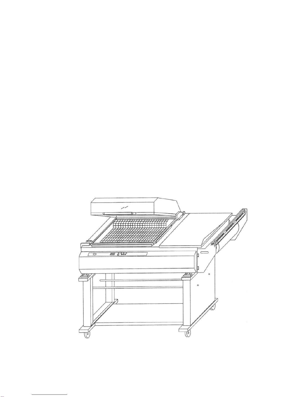
The REEL and FILM DIVIDING TABLE slide
forwards and backwards to suit the size of film
and product being used. The WIRE
PRODUCT TRAY can be raised or lowered
inside the chamber using the hooks at the
back and the 2 screws at the front. The tray
should normally be positioned so that the
seal appears about half-way up the side of
the product
Micro Switch StrikerAdjustment
The adjustable pin which operates the
machine micro-switch has been pre-set and
its adjustment locked by means of two nylon
nuts. If for any reason this adjustment should
be lost or altered during operation then the
striker should be reset GENTLY to strike the
micro-switch, IF THE MICRO-SWITCH
STRICKER IS SET TOO LOW IT WILL
DAMAGE THE OPERATING
MICRO-SWITCH

OPERATION
The way to thread film:
Adjust the position of the connector
shaft through pulling the sphere-type
handle(the black sphere on the two side
of connect shaft) to locate it at the
lowest point of the “ ”groove
Thread the film across between the
rubber roller and the connector shaft
pass the lower and upper edge of the
film under and over separator
respectively
In according with customers ’s
request ,you can adjust click pulley to
stitch the film.If so , please move the
connector shaft to the right of the “ ”
groove to make spike press the rubber
roller closely
Draw the leading edge of the film from Right
to Left into the chamber area and cross the
sealing blade. Ensure the top and bottom
leaves of film around the dividing table are
equal in length, and operate the hood to
produce a seal on the Left –hand end of the film
Remove the waste film-cut off by this operation
from inside the chamber
Place your product on top of the dividing
table and inside the film –against the fold
at the back. and the seal at the Left–hand side
Draw product and film into the chamber and
place approximately 10mm or 15mm from the
front and side seals .Operate the hood and the
shrink/seal process is carried out automatically
with the hood opening on completion of the
cycle.
If the film is not fully shrunk –increase
MAGENT TIMER and /or TEMPERATURE
until
good results are obtained.
If the film burns or punctures-reduce
TEMPERATURE and/or MAGENT TIMER
until
good results are obtained.
FILM SIZE/ADJUSTMENT
Select a suitable film width for your
Product (-usually WIDTH OF PRODUCT (front
To back) and HEIGHT OF PRODUCT + about
75mm), Fit the film on the reel carrier with the
folded side to the rear of the machine .and
thread as described previously. The front
OPEN side of the film should be about 50mm
Over the front seal blade, and the DIVIDING
TABLE should be positioned so that inside the
film it is about 20mm from the folded edge.
DO NOT attempt to seal and shrink if there
is any tension on the film as the hood is
closed -the pack will split open as it shrinks.
ALWAYS allow the film to be relaxed as the
seal takes place.
If the film BALLOONS and does not shrink
fully around your product-then the machine is
making too good a seal !Use one or both sets
of perforator wheels on the reels carrier during
the shrink process
TAKE CARE –THE PERFORATOR
WHEELS HAVE SHARP SPIKES which are
behind the film during operation but which are
EXPOSED DURING ADJUSTMENT AND
FILM THREADING
the upper edge rubber roller click pulley
the low edge
film

GENERAL MAINTENANCE
Operations to be carried out by the machine
operator.
The machine operates with plastic films
which may leave deposits on the sealing blade
and so effect quality
The sealing blades:
Keep the sealing blades clean by using a rag
or NON-METALLIC scraper (or
thumb –nail!)and keep the Teflon tape on the
both top jaw clear in same way .Apply a
SILICONE LUBRICANT spray to both top and
Bottom jaws, several times a day, for easier
And cleaner machine operation.
Transparent hood:
The transparent machine hood may be kept
clean with glass polish or similar-DO NOT
USE SOLVENT CLEANERS
CAUTION IN OPERATION
To in order to make your packaging products
Sealed and shrunk completely, you can operate
The machine as following:
1.To in order to shrink the product, you must
make the chamber to be hot by opening and
closing the hood repeat when you start or you
are asked to
operate again in the case of your operation is
interrupted.
2.the experience is important to seal and
shrink .you will know the appropriate sealing
time\shrinking temperature and operating
frequency by operating the machine
continually.
3 Yu will be known that only have a good
product sealer, your product will be shrunk
completely. So when you operate the machine
for sealing or sealing and shrinking, you can
close the hood with your high hand, almost at
the same time, pull the film by the waste
film to move from left to right after sealing time
is finished.
ROUTINE MAINTENANCE
It is advisable to use two qualified people for
Maintenance .
BEFORE ATTEMPTION ANY
MAINTENANCE TURN MAIN SWITCH OFF
AND DISCONNECT POWER SUPPLY!
CAUTION HOT!! CAUTION HOT!!
SEALING BLADE REPLACEMENT
Undo the screws on the expansion blocks and
the central knuckle. Remove the broken seal
blade and fit new one after cleaning the sealing
base of any deposits/dirt. Apiece of Teflon tape
around the corner of the wire helps seal quality
and insulation of heat. Introduce the end of the
front seal blade15mm inside the plunger to the
RIGHT I order to compress the spring .then
tighten the screws ,Repeat the process with the
tighten the screws on the center buckle.
SILICONE RUBBER REPLACEMENT
The silicone rubber strip inside the top jaw
must remain flat and undamaged .if it is
necessary to replace the rubber, pull the
damaged strip out and clean away any silicone
adhesive. Replace the rubber strip using fresh
silicone adhesive sparingly. Leave to cure
overnight.
REGULAR REPLACEMENT of the TEFLON
BARRIER TAPE will increase the life of the
Silicone rubber.
TEFLON BARRIER TAPE REPLACEMENT
Remove old Teflon barrier tape before it burns or
marks bodily. The tape is supplied on a roll,
with self-adhesive backing. Simply cut to
length .Remove backing protection and stick in
place.

TROUBLE SHOOTING
THE HOOD WON’T STAY OPEN
Torsion bar out of adjustment? Torsion bar broken ?
Solution: Replace the torsion bar
THE HOOD WON’T STAY OPEN
COMPLETELY
Solution: Tighten the special screw.
FAILURE TO CUT FILM CLEANLY
Sealing blades dirty? Seal time too low?
Solution: Check the clamps of the sealing
wire and make sure that the latter is not
broken, replace if interrupt.
Adjust according to the type of
film.
SEAL SPLITTING
Seal timer too high? Film under tension
during seal?
FAN WON’T CYCLE
Operating micro-switch out of adjustment
or broken? Toggle switch set to seal only?
motor condenser of fan motor faulty?
SEALING BLADE LEAVES SEALING BASE
Worn sealing base? Seal time too low?
Operator not detaching film before the hood
opens?
THE PACKAGING IS AWOLLEN AFTER
SHRINK-WRAPPING
The film used is not micro-perforated?
Solution: Make the film pass through the
Micro-piercing device of the machine.
ELECTRO-MAGNETS WON’T CLAMP
Magnet pole pierce pads out of
adjustment? Magnet timer set too
low/defective?
INCOMPLETE SEAL
Solution: Check sealing blades and
Teflon tape for cleanliness. Clean and
lubricant
With silicone. Check Teflon tape for
burning
And/or wear-
Replace if necessary. Check silicone rubber
in top jaw( beneath Teflon tape ).If cut or
damaged ,replace.
HEATERS NOT OPERATING
Toggle switch set to seal only?
Temperature controller set low?
Temperature
controller /thermocouple/elements defective
MACHINE NOT –BUT NO SHRINK
Film type/grade correct?( some plastic
film do not shrink ). Shrink temperature
incorrect for this type of material? Fan
impeller
loose on motor shaft?
The mistake cue for PC board:
1.E1 detect abnormal temperature sensors showed :
Said sensor signal not access, circuit breaking
Where : check processing break, and then a good
job.
2.Show for E2, 20 minutes at 80 ° C below the
temperature to at least one year.
Reasons : use of a temperature sensor short circuit, or
from the sensor, which was less than the actual
signal.
3.For the E3 show, at 35 minutes, the temperature is
consistently below target temperature.
Reasons : heater fault or sensor from the sensor, but
the actual temperature is over 80 ° C.

PARTS LIST, FIGURE 1 ASSEMBLY OF THE STAND
KE
Y
Q'T
Y
PART NO. DESCRIPTION FPH-204-016
11 2 7-01000-111 Upright
12 1 7-01000-121 Lower platform
13 2 229A075PU-BK Wheel,swivel 75mm
13.1 2 229C075PU-BK Wheel fixed 75mm
14 2 7-01000-140 Basket bracket shaft
100 8 200A08045 Socket head cap screw, M8*45
101 8 202A0816 Plain washer, M8*16
102 8 202B08 Lock washer, M8
103 8 201A08 Hex nut, M8
104 4 200AR08016 Socket screw, M8*16
105 16 200M06012 Hex bolt with washer, M6*12
106 1 202A082230 Plain washer, M8*22*3
107 1 7-01000-150 Waste film basketry
10

103
101
11
and replaced if worn or broken.Failure to
All parts must be periodically inspected
102
105
13
and present a safety hazard.
do this can affect a tool's operation
WARNING
13-1
14
101
100
12
FIGURE 1: ASSEMBLY OF THE STAND
104
107

PARTS LIST,FIGURE 2-4 HOOD UNIT
KE
Y
Q'T
Y
PART NO. DESCRIPTION FPH-204-022
11 1 7-02000-112 Hood
12 2 7-02000-120 Transparent hood seat I
12.1 2 7-02000-121 Transparent hood seat II
13 1 7-02000-130 Handle
14 1 7-05000-110 Rim
15 2 7-05000-120
A
luminum seat (long)
15.1 2 7-05000-121
A
luminum seat (short)
16 2 7-05000-130 Sponge strip(long)
16.1 2 7-05000-131 Sponge strip(short)
17 14 7-02000-200 Spring buckle
18 0.15 297F0075
A
dhesive
19 1 7-05000-300 Proximity switch adjustable screw
20 1 7-05000-280
A
djusting screw bracket
21 1 7-05000-290
A
djusting nut
22 1 7-05000-310 Proximity switch cover
23 1 7-05000-390 Hinge pressing bar
24 1 7-05000-262 Supporting seat
25 1 7-02500-250
A
ctive cupule
26 1 7-02500-261 Sponge washer
100 2 200A08016 Socket head cap screw, M8*16
102 2 202B05 Lock washer, M5
103 2 202A0510 Plain washer, M5*10
104 2 200A05012 Socket head cap screw, M5*12
105 1 200A05035 Socket head cap screw, M5*35
106 1 103T024B Solenoid 24VDC
107 1 202F062503 Silica gel washer
108 1 104H1307 Proximity switch
109 4 200E04008 Phillips head machine screw, M4*8
100 2 200A08012 Socket head cap screw, M8*12
110 2 201A08-1 Hex nut, M8
111 2 200H04008 Truss head machine screw,M4*8
112 2 202A0409 Plain washer, M4*9
113 2 202A0816 Plain washer, M8*16
114 2 202B08 Lock washer, M8
12

114
113
21
All parts must be periodically inspected
and replaced if worn or broken.Failure to
do this can affect a tool's operation and
present a safety hazard.
WARNING
13
100
106 25
107 15-1
105 26
15
18
108
16
18
20
19
111
109
104 103
110 24
102 14 16-1
15-1
109
112
23
12
17
22
FIGURE2-4: HOOD UNIT
11
12-1
115
13

PARTS LIST,FIGURE 3-6 BASIN-RESISTOR UNIT
KE
Y
Q'T
Y
PART NO. DESCRIPTION FPH-204-038
11 1 7-03000-110 Hinge
12 1 7-03100-120 Hinge adjustable support (L)
12.1 1 7-03100-121 Hinge adjustable support (R)
14 1 7-03000-141 Fin fasting board
15 3 7-03000-320D Heating tube,220-230VAC 900W
16 1 7-03000-160 Rear panel
18 47-03000-180
A
nti-high tem.clothe
20 1 7-03800-200 Tra
y
21 3 7-03000-211 Tray uphold
22 2 7-03000-220 Heater transmission fastener
23 2 7-03000-230 Heating tube connector
24 1 7-03000-240 Fan protection
25 1 7-03800-250 Front panel
26 2 7-03000-260 Clip ring
27 1 7-03000-270 Fan hub
28 3 7-03000-280 Tray uphold screw
29 1 7-03100-290 Copper connector
30 1 7-03000-300 Fan
101 8 200E04008 Phillips head machine screw, M4*8
102 7 200H04016 Truss head machine screw, M4*16
103 11 200H04008 Truss head machine screw, M4*8
104 4 200A06020 Socket head cap screw, M6*20
105 2 200A05020 Socket head cap screw, M5*20
106 4 201G05 Hex nut, M5
107 8 202A061620 Plain washer, M6*16*2
108 1 200G08015 Socket head set screw, M8*15
109 4 200F04008 Flat head cap screw, M4*8
110 1 101C235060037 Motor, 220-240V/50-60Hz 370W
111 4 202F062503
S
ilica gel washe
r
112 1 104Y003 Thermocouple
14

28 21
109
107
102
20
23 22
104
107
110
and replaced if worn or broken.Failure to
WARNING
All parts must be periodically inspected
do this can affect a tool's operation
and present a safety hazard.
24
27
26
108
30
105
106
25
18
16
15
22
29
23
112
102
FIGURE 3-6: BASIN - RESISTOR GROUP
103
103
12 11
14
18
12-1
111
107
15

PARTS LIST, FIGURE 4 REEL CARRIERGROUP
KE
Y
Q'T
Y
PART NO. DESCRIPTION FPH-204-040
11 1 7-04000-110 Separator
12 1 7-04000-120 Film holder body
13 1 7-04000-130 Spinder
14 1 7-04000-140 Rubber roller
15 2 7-04000-150 Shaft
17 3 7-04000-170 Click pulley
18 1 7-04000-180
A
djusting bracket
19 3 7-04000-190 Scored pulley fastener
20 1 7-04000-200 Connector shaft
21 2 7-04000-210 Lock wimble
22 1 7-04000-220 Film shaft
23 1 7-04000-230 Conical spring
25 2 2201411055 Spring,1.4*11.4*55
26 2 7-04000-260 Holder guide support
28 2 7-04000-280 Slide
29 3 227A03528 Rubber washer, Ф28*3.55
30 6 200R06025 Star-type handle, M6*25
31 2 227BA-3008 Grip ball(Black)
100 4 200H05012 Truss head machine screw, M5*12
101 6 200H04015 Truss head machine screw, M4*15
102 2 200A05030 Socket head cap screw, M5*30
103 2 201A05 Hex nut, M5
104 4 200G06008 Socket head set screw, M6*8
105 2 210AF606ZZ Bearing F606ZZ
107 3 212AS20 Ring, S-20
110 1 212CR15 Snap pin-R15
16

FIGURE 4: REEL CARRIER GROUP
18
14
103
12
102
13 20
23
105
11
100
29
28
104
110
105
All parts must be periodically inspected
and present a safety hazard.
do this can affect a tool's operation
WARNING
and replaced if worn or broken.Failure to
19
31
28
100
21
30
17
30 29
107 25
15
22
Table of contents
Popular Packaging Equipment manuals by other brands

strapex
strapex SMA 20 operating instructions

Snell
Snell ES-103 Operating manual and Spare parts list

Rice Lake
Rice Lake ISHIDA WM-Nano Cleaning, Sanitizing and Inspection Instructions

U-Line
U-Line H-167 quick start guide

Minipack-Torre
Minipack-Torre continua user manual

vc999
vc999 07P Series Operator's manual