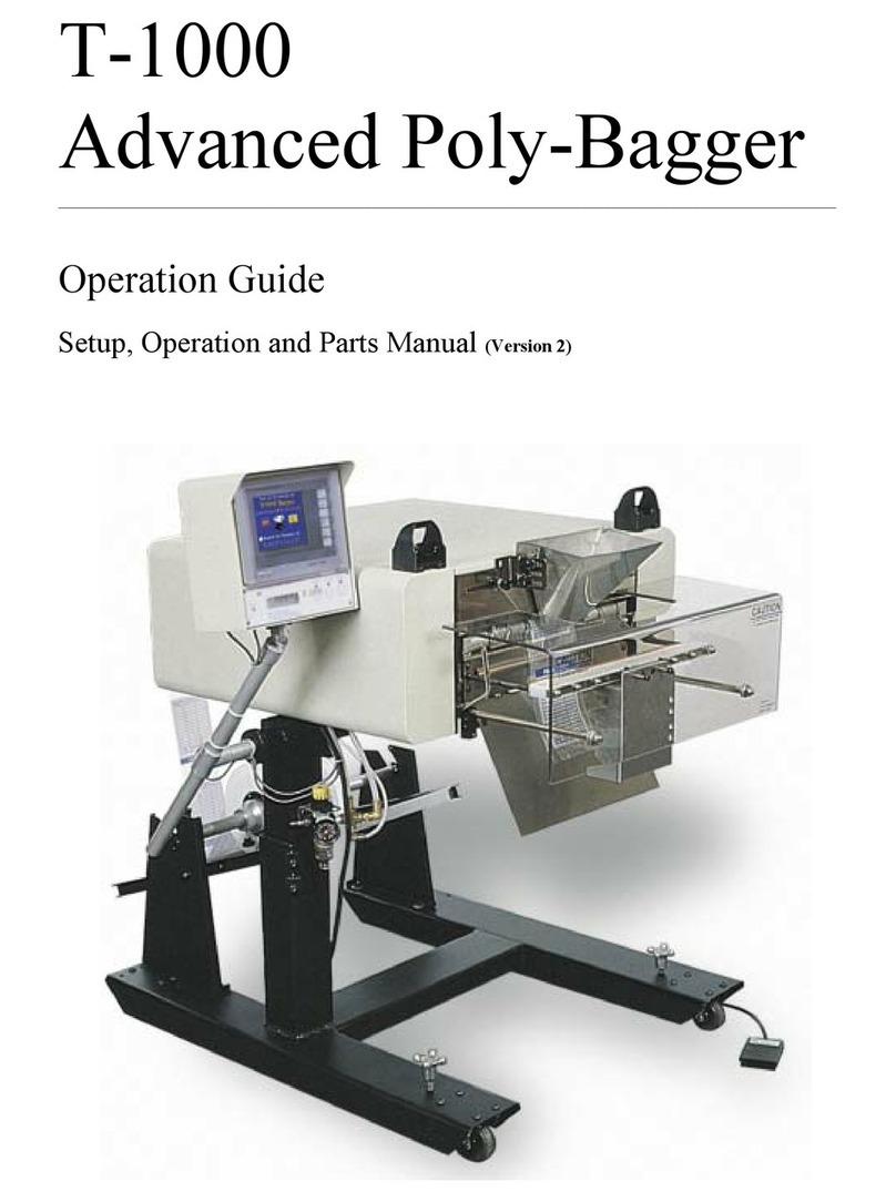
Advanced Poly-Packaging Advanced Poly-Bagger T-1000-S14 Installation manual

T-1000
Advanced Poly-Bagger™
(Model T-1000-S14)
___________________________________________________________________________
Operation Manual, Version 8 Revision A

Acknowledgments
Written By: Jen Sprandel
Edited By: Annie Braddock
Reviewed By: Stuart Baker
Copyright
2014 (Ver. 8), 2010 (Ver. 7) 2009 (Ver. 6), 2007 (Ver. 5), 2006 (Ver. 4), 2003 (Ver. 3), 2001 (Ver. 2), 1995 (Ver. 1), Advanced
Poly-Packaging, Inc. (APPI). All rights reserved.
This manual and the program operating the equipment described in it are copyrighted. You may not copy this manual in whole or
part without the consent of Advanced Poly-Packaging, Inc.
All information pertaining to the promotion, sale, distribution, operation and maintenance of the T-1000-S14 ADVANCED
POLY-BAGGER including this manual, drawings, schematic, wiring diagrams, VHF video tapes, brochures, specification sheets,
figures, charts, or any other information, due to its proprietary design and manufacture remain the property of Advanced Poly
Packaging, Inc. Unauthorized duplication, distribution or disclosure to third parties without the expresses permission of
Advanced Poly-Packaging, Inc. is strictly prohibited.
Trademarks
T-1000-S14 is a trademark of Advanced Poly-Packaging, Inc. Advanced Poly-Packaging, Inc. owns also the following
trademarks: Advanced Poly-Bags, Advanced Poly-Bagger, Seal-a-Print, Roll-a-Print, Twin-Seal, Teflon Shield, Advanced Poly-
Pack, Advanced Poly-Bag, Advanced Bag.
Limited Warranty and Disclaimer
Warranty period is 12 months or 1,000,000 cycles whichever comes first. The warranty commences on the date of delivery of the
equipment to the Purchaser. APPI warrants to the Purchaser that the equipment is free from defects in workmanship or material
under normal use and service. During the warranty period, APPI agrees to repair or replace, at its sole option, without charge to
Purchaser, any defective component part of the equipment. To obtain service, Purchaser must return the equipment or component
to APPI or an authorized APPI distributor or service representative in an adequate container for shipping. Any shipping charges,
insurance, or other fees must be paid by Purchaser and all risk for the equipment shall remain with Purchaser until such time as
APPI takes receipt of the equipment. Upon receipt, APPI, the authorized distributor or service representative will promptly repair
or replace the defective component and then return the equipment or component to Purchaser, shipping charges, insurance and
additional fees prepaid. APPI may use reconditioned or like new parts or units, at its sole option, when repairing any component
or equipment. Repaired products shall carry the same amount of outstanding warranty as from original purchase. Any claim
under the warranty must include a dated proof of delivery. In any event, APPI's liability for defective components or equipment is
limited to repairing or replacing the components. This warranty is contingent upon proper use of the equipment by Purchaser and
does not cover: expendable component part such as Teflon, thermocouple wire, heater cartridge, rollers, bushings, and the like; or
if damage is due to accident, unusual physical, electrical or electromechanical stress, neglect, misuse, failure of electric power,
water damage (from airlines), improper environmental conditions, transportation, tampering with or altering of the equipment,
packaging of corrosive or contaminating products or other products damaging to components, and equipment or components not
owned or in the possession of original Purchaser. APPI will not be liable for loss of production, profits, lost savings, special,
incidental, consequential, indirect or other similar damages arising from breach of warranty, breach of contract, negligence, or
their legal action even if APPI or its agent has been advised of the possibility of such damages or for any claim brought against
the Purchaser by another party. This warranty allocates risks of equipment failure between Purchaser and APPI. APPI's pricing
reflects this allocation of risk and the limitations of liability contained in this warranty. The warranty set forth above is in lieu of
all other express warranties, whether oral or written. The agents, employees, distributors and dealers of APPI are not authorized
to make modifications to this warranty, or additional warranties binding on APPI. Accordingly, additional statements such as
dealer advertising or presentations, whether oral or written, do not constitute warranties by APPI and should not be relied upon.
Warranty on equipment is considered void when outstanding balances become delinquent (over 30 days late - 60 days after ship
date). Equipment Integration to other Equipment: APPI assumes no responsibility for the integration of its products to other
products or within a system unless APPI performs the integration, testing and provides the results of the tests to the purchaser in
writing. Furthermore, APPI assumes no responsibility for bag sizing whether suggested or recommended.
.

1
Contents
Chapter 1: Introduction 5
1.1 Overview..........................................................................................................................6
1.2 Standard Features..............................................................................................................6
1.3 Using this Manual - Typographical Conventions...............................................................6
1.4 Warranty Registration.......................................................................................................7
Chapter 2: Safety, Getting Started 9
2.3 Threading Diagram...........................................................................................................9
2. Getting Started..................................................................................................................10
2.1 Safety, Risks...................................................................................................................10
2.2 Quick Setup Procedures: .............................................................................................11
2.3 Threading Diagrams........................................................................................................11
Chapter 3: Touch Screen Operation 15
3. Touch Screen Operation....................................................................................................16
3.1 Touch Screen Identification ............................................................................................16
3.2 Touch Screen Brightness Adjustment..............................................................................16
3.3 Touch Screen Program, Overview...................................................................................17
3.4 Introductory Screen.........................................................................................................17
3.5 Operation Screen ............................................................................................................17
3.6 Main Menu .....................................................................................................................17
3.7 Settings Screen ...............................................................................................................18
3.8 Fill Time.........................................................................................................................18
3.9 Air Pulse.........................................................................................................................18
3.10 Seal Point......................................................................................................................19
3.11 Seal Time......................................................................................................................19
3.12 Reverse.........................................................................................................................19
3.13 Blow Off.......................................................................................................................19
3.14 Index Speed ..................................................................................................................19
3.15 Seal Temperature..........................................................................................................19
3.16 Options Menu ...............................................................................................................20
3.17 LS-10 Load Shelf..........................................................................................................20
3.18 FS-10 Flat Seal Assembly.............................................................................................20
3.19 CS-10 Compartment Seal..............................................................................................21

2
3.20 TS-10 Twin Seal Feature...............................................................................................21
3.21 Ti-1000Z Printer............................................................................................................21
3.22 CF-10 Counting Funnel.................................................................................................21
3.23 BO-30 Bag Opening Device..........................................................................................22
3.24 LC-10 Light Curtain......................................................................................................22
3.25 TIZ RAP / Accumulator................................................................................................23
3.26 AF-10 Accumulating Funnel.........................................................................................23
3.27 BO-20 Bag Open Detector............................................................................................24
3.28 US-5000 / US-5500 Semiautomatic Net weigh Scale ....................................................24
3.29 PB-20 Palm Buttons......................................................................................................24
3.30 TS-10 Trim Seal Assembly...........................................................................................24
3.31 ES-10 Estop Circuit ......................................................................................................25
3.32 MV-10 Seal Validation.................................................................................................25
3.34 DF-20 Part Diverter ......................................................................................................26
3.35 Medical Flat Seal..........................................................................................................26
3.36 BF-10 Bag Deflator.......................................................................................................27
3.37 UF-5000 Infeed Conveyor Operation Screen.................................................................27
3.38 BV-10 Barcode Reader Option......................................................................................27
3.39 Ti-1000 Inline Printer....................................................................................................27
3.40 Counters Screen............................................................................................................28
3.41 View Settings, Job Save & Recall .................................................................................28
3.42 Internal and External Memory.......................................................................................28
3.43 Production Graph and Temperature Graph....................................................................29
3.44 Operation Mode Timers, Alarms, Alarm Data...............................................................30
3.45 Auxiliary Screen ..........................................................................................................30
3.46 Machine Info.................................................................................................................31
3.47 Technical Assistance & Troubleshooting Screens..........................................................31
3.48 Warning and Message Screens......................................................................................31
3.49 Notes ...........................................................................................................................33
Chapter 4: Adjustments Maintenance, Troubleshooting 35
4.1 Machine Adjustments.................................................................................................36
4.2 Tracking and Alignment Adjustments.........................................................................36
4.3 Compression (Nip) Roller Adjustment........................................................................36
4.4 Dancer assembly Adjustments....................................................................................39
4.5 Dancer Bar and Break Strap Adjustment.....................................................................39
4.6 Upper Roller Guides...................................................................................................39
4.7 Teflon Adjustment......................................................................................................39

3
4.8 Teflon Replacement....................................................................................................40
4.9 Pressure Bar Adjustment.............................................................................................40
4.10 Sealer Cylinder Adjustment........................................................................................40
4.11 Pressure Bar (Rubber) Replacement............................................................................43
4.12 Anti-Jam Adjustment.................................................................................................43
4.13 Heater Cartridge Replacement ....................................................................................46
4.14 Replace Thermocouple Wire......................................................................................48
4.15 Preventative Maintenance and Scheduled Maintenance...............................................48
4.16 Preventative Maintenance Checklist ...........................................................................50
4.17 Scheduled Maintenance Chart.....................................................................................51
4.18 Preventative Maintenance Chart .................................................................................51
4.19 Spare Parts Kits..........................................................................................................52
4.20 Troubleshooting Guide ...............................................................................................54
4.21 Troubleshooting Checklist ..........................................................................................55
4.22 PLC IO Listing...........................................................................................................56
4.23 Electrical Drawings ....................................................................................................57
4.24 Troubleshooting Notes / Technical Support Information.............................................70
Chapter 5: Parts and Drawings 71
5.1 T-1000-S14 Advanced Poly-Bagger ...........................................................................72
5.2 Base Assembly...........................................................................................................74
5.3 Upper Column Assembly............................................................................................75
5.4 Covers and Guarding..................................................................................................76
5.5 Flat Load Shelf Assembly...........................................................................................77
5.6 Dancer Assembly........................................................................................................78
5.7 Touch Screen Assembly .............................................................................................79
5.8 Main Frame Assembly................................................................................................81
5.9 Air Knife Assembly....................................................................................................84
5.10 Sealer Frame Assembly: Drop Frame..........................................................................85
5.11 Electrical Panel...........................................................................................................94
5.12 Notes:.........................................................................................................................96

4
This page is intentionally left blank.

5
Chapter 1: Introduction
1.1 Overview
1.2 Standard Features
1.3 Using This Manual

6
1.1 Overview
T-1000 Advanced Poly-Bagger™is a general purpose bagging system designed for manual or automatic
packaging of a variety of products.
1.2 Standard Features
The machine comes standard with the following features:
Energy Conservation & Component Saver –Extends component life and conserves energy.
Pass Code Protection –Restricted access to settings can be enabled (Level 2 pass code). Factory settings
protection is always enabled (Level 1 pass code).
Counters –Preset, Total and Maintenance counters are provided.
Communications Ports –Provides for auxiliary communications.
Anti-jam Device –Detects rigid objects of at least 3/8”to safeguard the equipment and product.
Internal (PLC) and External (USB) Recipe Management System –stores up to 30 Recipe settings
internally, or hundreds of recipes externally. Optional Ethernet card can allow for remote recipe
management.
Auxiliary Automatic Operation –Integrates automatically to vibratory counters, scales and other in-feed
equipment.
1.3 Using this Manual - Typographical Conventions
The following manual conventions are frequently used to assist in understanding important information,
alerting the operator of potentially dangerous or damaging practices, and the normal functions of the
T-1000 Advanced Poly-Bagger™.
text Normal text
<ENTER> Used to show Touch Screen keys
Italics Used for emphasis
CAUTION: Warning messages - To avoid physical harm, damage to equipment or
damage to the product. Be sure to read these messages carefully.

7
1.4 Warranty Registration
This section must be completed and returned to Advanced Poly-Packaging, Inc. to register the T-1000
Bagger for Warranty Protection.
Serial Number:
(Serial Number located on the back panel)
Company Name and Address Contact Name(s) / Title(s) / Phone Number
________________________________
________________________________
________________________________
________________________________________
________________________________________
________________________________________
Please fax or mail this page to:
Service Manager
Advanced Poly-Packaging, Inc.
1331 Emmitt Road
Akron, OH 44306
USA
Fax # (USA) 330-785-4010
Or email the information above to: sales@advancedpoly.com

8
This page intentionally left blank.

9
Chapter 2: Safety, Getting Started
2. Getting Started
2.1 Risks, Safety Precautions
2.2 Quick Setup Procedure
2.3 Threading Diagram

10
2. Getting Started
This chapter describes risks, required safety precautions and quick start procedures.
2.1 Safety, Risks
The equipment has been designed with features to reduce the possibility of injury. Despite safety
precautions, operators may receive lacerations, minor burns or crushed or broken bone injuries if coming
in contact with the heater bar or other moving components. Please carefully read the following
precautions to operate the equipment properly and avoid injury.
Although no special personal protective equipment is required to operate the equipment, eye protection,
gloves or other protection should be worn depending on the characteristics of product being packaged or
the method of loading the product.
CAUTION: Initial Setup of the machine must be performed by Specialized Personnel. Qualified
Service Engineers should uncrate, assemble (if required), test and connect power sources, test the
equipment for proper operation and otherwise setup the equipment for use.
CAUTION: Maintenance must be performed by Specialized Personnel. Qualified Service Engineers
must remove guards or covers to gain access to electrical or mechanical areas.
CAUTION: To avoid injury do not reach under the equipment or guards. Do not place hands or
fingers in the seal area, near the seal or heater bar, load shelf, or other moving components.
CAUTION: To avoid injury, do not operate the equipment if funnels, guards or covers or other access
panels have been removed.
CAUTION: To avoid injury, do not reach under guards or elsewhere under the machine.
CAUTION: Do not remove or loosen fasteners on the frame. If loosened the equipment may drop
suddenly causing injury or damage to the machine.
CAUTION: Do not attempt to adjust the height without assistance and without supporting the weight
of the machine.
CAUTION: Be careful when opening the seal frame as it may drop suddenly causing injury or
damage to the equipment.
CAUTION: To avoid injury, avoid coming in contact with pinch points including rollers, automatic
funnel doors or other moving components.
CAUTION: To avoid injury, avoid contact with Roller "Fingers" as they may be sharp.

11
2.2 Quick Setup Procedures: (perform prior to operating the machine on a daily basis)
Considering that the machine has been setup by Maintenance Personnel, the following quick start
procedures should be followed before daily operation of the equipment.
Power off tasks (perform these tasks prior to turning on the power):
Clean the blue rubber roller, print rollers, perforation sensor, idler rollers and product contact surfaces
with a clean cotton cloth and alcohol.
Inspect the machine to ensure all guards, covers and funnels are in position.
Inspect the machine for maintenance issues and report issues such as loose or broken components, frayed
wires, etc. to maintenance personnel.
Check that the air pressure is set to 60 psi.
Power on tasks (perform these tasks after cleaning and inspecting the machine)
Threading: A threading diagram has been provided to illustrate the proper bag path through the machine.
It is recommended that the appropriate diagram be copied and mounted to the side cover of the machine.
Setup Cycle Operation: Prior to loading parts, place the bagger in the Start / Manual / Setup mode and
press the footswitch or touch the <Manl Cycle> button. Test the bag seals, seal location or other
inspection requirements.
Manual Cycle Operation (if applicable): If manually loading parts, load parts into the bag ensuring all
parts are going into the bag. Toggle the machine from Setup mode to Manl mode. Press the <Manl
Cycle> button on the screen. Inspect the bag seals, seal location or appearance and continue the bagging
operation.
Automatic Cycle Operation (if applicable): If loading automatically with a conveyor, counter or scale
infeed system, ensure auxiliary equipment is turned on and press the <Manl Cycle> button to start the
system. If all equipment in the system is operating properly, toggle the machine from the Manl mode to
the Auto mode.
2.3 Threading Diagrams
Several threading diagrams are available based on the configuration of the bagger or the options ordered.
Select the configuration: standard vertical, horizontal, or horizontal incline. Then, select with printer or
without. Finally, select single or double dancer. Double dancer is for longer bags. This manual may not
contain the proper threading diagram for your specially or custom configured machine. Please contact
Technical Support to obtain a copy of the correct threading diagram.

12
Threading Diagram, Standard Vertical, Single Dancer

13
Threading Diagram: Standard Vertical, Single Dancer, with Ti-1000 “Z”Printer

14
This page is intentionally left blank.

15
Chapter 3: Touch Screen Operation
3.1 Touch Screen Identification
3.2 Brightness Adjustment
3.3-3.48 Touch Screen Programs
3.49 Notes

16
3. Touch Screen Operation
This section describes in detail, the identification, operation and adjustments of the Touch Screen
Program.
3.1 Touch Screen Identification (See Fig. 3-0)
1 System Button
2 F1 (Help Screen)
3 F2 Increase Brightness (when system button is pressed)
4 F3 Midpoint Brightness (when system button is pressed)
5 F4 Decrease Brightness (when system button is pressed)
6 F5 Job Save / Recall
8 Green LED (Power): Lit when Touch Screen is turned on
3.2 Touch Screen Brightness Adjustment
The brightness of the LCD may be adjusted if the screen is difficult to read. To adjust the contrast, press
the <System> button, then press <F2> button to increase brightness or <F4> button to decrease
brightness. <F3> resets brightness to the default setting.

17
3.3 Touch Screen Program, Overview
The Touch Screen Program is a "user-friendly" menu-driven setup and operation program. Pop-up
windows are incorporated for quick and easy setting adjustments. Each time a setting is changed, the
settings are saved so that if power is lost, the “job”will be recalled automatically without the need for
reprogramming.
A general color scheme has been used to identify
functions:
Blue: Background color. Blue is used as a
background or text-only color, which when pressed
typically does nothing.
Yellow: Menu buttons which will take you to other
areas in the program.
Green: Setting buttons used to change settings or
mode of operation.
Red: Stop, off functions or warning messages.
3.4 Introductory Screen
When the T-1000 is turned on, an Introductory
screen is displayed. See Figure 3-1.
3.5 Operation Screen
Operation Screen is provided to function with Pass
code Protection function of the machine. If the
pass code function is enabled in the Technical
Assistance Screen, the touch screen will default to
the Operation Screen after a preset time has
elapsed. This function prevents unauthorized
operators from making setting changes that could
affect the operation or performance of the unit.
Since no settings are displayed on the Operations
Screen, the operator cannot change settings unless
a pass code is enabled. See Figure 3-2. There are
several Operations Screens, which are selected
based on the Operation, Auxiliary and Options
installed. Figure 3-2 is the most basic operation
screen sample.
3.6 Main Menu
Main Menu screen allows the operator to quickly
navigate to other areas. See Figure 3-3.
Mode toggle buttons are located at the top of many
screens:
<Start> / <Stop> toggle button controls operation
mode, the mode which enables the equipment to
cycle.
<Manl> / <Auto> toggle button activates the
Automatic (paced rate) or Auxiliary Cycle mode.
<Run> / <Setup> toggle button deactivates functions and allows cycling when not at temperature.
Setup mode stops counters, production timers and auxiliary signals so that the equipment can be operated
Figure
3
-
1
Figure
3
-
2
Figure 3-3

18
independently in a setup mode.
Ready/Waiting LED displays Ready when the heater bar temperature is in the range of acceptance.
Waiting flashes when the machine is not at temperature. Waiting pauses the operation unless in the setup
mode.
3.7 Settings Screen
Settings Screen provides access to the basic
machine settings. Bag size, thickness and product
characteristics affect settings required for the
proper operation of the machine. See Figure 3-4.
All settings will be entered numerically on a
keypad. To adjust any value, press the green button
of the setting which you would like to change, then
enter the value on the number keypad followed by
the <Enter> button.
The Settings Menu is where most entries and
machine operation settings will occur to setup a
new bag size or to run a new product.
3.8 Fill Time
The <Fill Time> button functions differently dependent upon the MODE in which the T-1000 is
operating: MANUAL, AUTOMATIC (<AUTO>) mode or AUXILIARY mode.
In the Manual mode with NO accumulating funnel, Fill Time will delay the operation from starting until
this time has passed. When equipped with an accumulating funnel, Fill Time will affect the delay time
before sealing, after the accumulating funnel door has closed.
In the AUTO cycle mode with no auxiliary in-feed equipment, Fill Time affects the paced rate operation.
The bagger will automatically cycle with the Fill Time delaying the seal bar after the bag has been blown
open. In the AUTO mode a footswitch is not required.
CAUTION: To avoid physical harm, DO NOT cycle the equipment in the AUTO mode if the funnel,
guards or covers are removed. Since the seal bar actuates automatically, operators must keep fingers,
hands and other parts of the body away from the sealing mechanism and all other moving parts.
AUXILIARY cycle mode, FILL TIME displays the time which a product, automatically filled by
auxiliary equipment, has to be completely settled in the bag before the seal bar is actuated.
Typical setting for manual loading with a footswitch is 0.0 seconds. Typical setting for auxiliary
equipment / automatic loading is 0.5 seconds. The lower the setting, the faster the operation. However,
too low of a setting could cause the seal bar to contact the product, possibly damaging the product or seal
components.
3.9 Air Pulse
The amount of time that a burst of air will initially blow the bag open. Wider bags and heavier gauge
bags require a longer burst of air. Additionally, to increase the volume of air from the air pulse tubes, turn
the Air Pulse valve counter-clockwise. Flow control valves are located on the right lower side of the seal
frame assembly to increase or decrease air through the air pulse tube or blower.
Figure 3-4
Other manuals for Advanced Poly-Bagger T-1000-S14
1
This manual suits for next models
1
Table of contents
Other Advanced Poly-Packaging Packaging Equipment manuals

Advanced Poly-Packaging
Advanced Poly-Packaging T-300 User manual

Advanced Poly-Packaging
Advanced Poly-Packaging Advanced Poly-Bagger T-1000 User manual

Advanced Poly-Packaging
Advanced Poly-Packaging Advanced Poly-Bagger T-1000 User manual

Advanced Poly-Packaging
Advanced Poly-Packaging Advanced Poly-Bagger T-1000-S14 User manual

Advanced Poly-Packaging
Advanced Poly-Packaging T-375 User manual

Advanced Poly-Packaging
Advanced Poly-Packaging Advanced Poly-Bagger T-1000 User manual

Advanced Poly-Packaging
Advanced Poly-Packaging Advanced Poly-Bagger T-1000 User manual