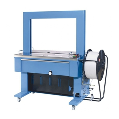
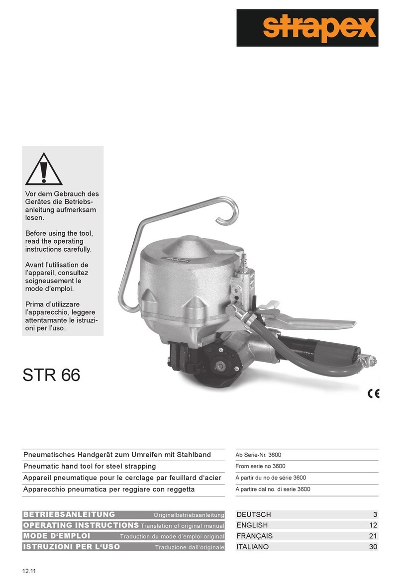
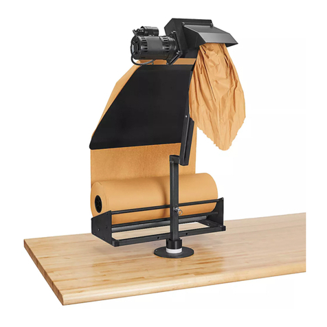
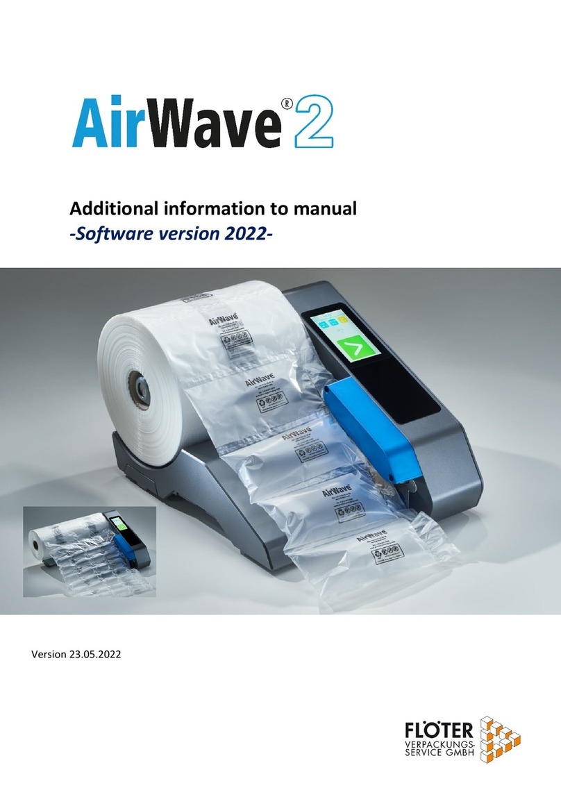
Transpak TP-6000-1 Guide

SPARE PARTS LIST
OPERATION MANUAL
TP-6000-1
STRAPPING MACHINE
AUTOMATIC POLYPROPYLENE
&
TP-6000CE1
KEEP ITWELL
IMPORTANT!
TP-6000CE3
TP-6000-3

Explanations For Each Model No. :
TP-6000-1 : Single Phase Model
TP-6000-3 : Three Phase Model
TP-6000CE1 : Single Phase With CE Version
TP-6000CE3 : Three Phase With CE Version
01/18/08

PART I
CONTENTS
1~2
2. Construction and Function of Units………..……..…….. 3
4
4. Control Panel …………………………..………………. 5
Control Panel (CE Version) …………………………..… 6
5. Electric Control Unit …………………………..………
…
7~8
6. How to Load P.P. Strap ………………..……………….. 9
7. How to Operate …………..…………………………….. 10
8. Recommend for Trouble-free Operation……..………… 10
9. Adjustments ……………...……………………………… 11~14
10. Installation of Arch Unit………………………………
…
15~16
11. Wiring Diagram …………………………………………17~21
12. Troubleshooting …………..……………………………
…
22
1. Safety Instructions………..……..……………………….
3. Technical Data …………………………..………………
.
01/18/08

(1) Before operating
a. Please always wear proper eye protection and safety gloves before operating this
Eye protection must be worn Safety gloves must be worn
b. Please make sure if the power voltage is correct.
c. It can only be operated with P.P. strap; not PET strap or Polyester cord strap.
(2) During operating
a. The weight of package should not exceed 100kg, and the size should not be
less than 100mm (width) x 20mm (high).
b. Check if the machine emits any smokes or unusual sound when it is running.
(3) After operating
a. Please pull out the power plug.
b. Please get rid of the dirt or impurity on the machine.
(4) Signs
Caution, risk of electric shock Do not touch!
Heiss!Hot! chaud!
c. Warning
c-1 For your own safety, please read instruction manual before operating. Keep
away from arch while the machine is running.
c-2 Do not put your hands or body into the Archworking area when the machine is
machine.
running.
-1-
1. Safety Instructions
01/18/08

a. Please turn off the power before opening the top plate.
b. Please do not touch the heater due to the high temperature.
c. Be careful with the heater if you open the upper top plate.
(5) Maintenance
(6) Other remainders
a. Do not alter or bypass protective interlocks
b. The operation manual must remain attached to the machine at all times
c. Do not alter circuits and machine unless authorized to do so by the manufacturer.
d. All electrical apparatus must be properly grounded.
e. Wire the machine according to the local electrical code.
-2-
01/18/08

-3-
2. Construction and Function of Units
1 Strapping head unit
machine for cutting and sealing of P.P.
This unit is the most important part of the
strap.
This is the arch track through which
P.P. strap forwards or reverses.
2 Bandway unit
5 Feed unit
Feeding and reversing of strap.
Holds the strap coil.
4 Reel unit
This unit accumulates the quantity of
strap required for smooth feeding into
3 Accumulator unit
the arch track.
6 Electric control unit
(If strap core is 280mm,
you can take off the center
drum to have core size 200mm.)
01/18/08

-4-
3. Technical Data
Sealing method Heat
Strap width:
Strap thickness:
Strap reel diameter:
Width :
Depth:
Table height:
Electrical connection:
0.55 mm up to 0.75 mm (0.022" - 0.03")
200 mm (8" nominal)
1430 mm (56.3")
620 mm (24.4")
810 mm (31.9")
AC 110V/220V/230V/240V (50/60Hz), 1PH
AC 220V/380V/400V (50/60Hz), 3PH
220 kg (341.7 lbs.)Weight: 83 dB (A)Noise emission: 5°C ~ 40°C (41°F ~ 104°F)Ambient temp:
8 mm to 12 mm (3/8"-1/2")
01/18/08

completed only after actuation of
operation. A strapping cycle is
This is the switch to start a strapping
1 Start switch
this switch.
2 Stop switch
Push the stop switch in case of emergency.
Simply push this stop switch to
completely stop the strapping operation.
*Lock stop switch if strapping has to be
interrupted for a short period of time. The
machine will stop but the heater element
will maintain its temperature. The machine
will then be immediately ready for operation
element.
without need for warming-up of the heater
3 F/R switch
switch is on, turn this switch counterclockwise
After P.P. strap is fed and the power supply
(Feed and Reverse)
strap reverses and returns strap from the
When the switch is turned clockwise, P.P.
to feed P.P. strap around arch.
arch track to the accumulator box.
4 Power supply switch and pilot
lamp
electric power is being supplied.
on, the pilot lamp lights up, showing that
When the power supply switch is turned
5 Auto/Hand selector switch
While selector switch is placed to the position
"AUTO", the machine will automatically strap
the package when it is placed on the table and
passes the arch, (the strapping cycle will
continue, if the package remains under the
arch. ) While the selector switch is
placed to the position "HAND", after
positioning the package under the arch,
be applied.
push the "START" switch, then one strap will
6 Reset switch (Option)
home position sealing This switch has
(Page 5 of part ), When strap no atⅡ
If the machine is with short feed sensor
reset function.
-5-
4. Control Panel
a. (For Standard Version)
01/18/08

actuation of this switch.
A strapping cycle is completed only after
This is the switch to start a strapping operation
1 Start switch
3 F/R switch
(Feed and Reverse)
After P.P. strap is fed and the main power switch is
on, turn this switch counterclockwise to feed P.P.
the arch track to the accumulator box.
clockwise, P.P. strap reverses and returns strap from
strap around arch. When the switch is turned
4 Power pilot lamp
When the main power switch is turned on, the pilot
lamp lights up, showing that electric power is being
supplied. If the machine has the short feed sensor,
has reset function and lights up if under power.
5 Auto/Hand selector switch
While selector switch is placed to the position ,
the machine will automatically strap the package
to the position , after positioning the package under
remains under the arch. ) While the selector switch is placed
( the strapping cycle will continue, if the package
be applied.
the arch, push the "START" switch, then one strap will
When strap no at home position sealing this switch
-6-
b. (For CE Version)
01/18/08

will cut off power automatically. For
In case of overload, the over load relay This Timer, T1, determines
Magnetic switch 6
normal operation, please actuate
this switch.
Timers 7 & 8
Timer , T1 7 :
This is a current protection device. the time necessary for strap take-up
Set Timer, T1, bearing in mind the time
required for strapping the minimum-size
package. Normally, Timer T1 is set
at about 0.4 seconds, but may have to be
adjusted depending on a package size.
This Timer, T2, determines
Timer , T2 8 :
the time necessary for strap feed
If the time selected for Timer T2 is
too short, strap may not reach the
sealing position.
Normally, Timer T2 is set to about 0.8
seconds for standard arch (850x600), but
may have to be adjusted depending on
arch size.
-7-
5. Electric Control Unit
a. (For Three Phase)
01/18/08

Normally, Timer T1 is set at about 0.3 seconds, but may have to be adjusted
Timer, T1, bearing in mind the time required for strapping the minimum-size package.
This Timer, T1, determines the time necessary for strap take-up. Set
Timers 30 & 29
Timer, T1 30 :
depending on a package size.
Timer, T2 29 :This Timer, T2 determines the Time necessary for strap feed. If the
time selected for Timer T2 is too short, strap may not reach the sealing position.
Normally, Timer T2 is set to about 0.7 seconds for standard arch (850x600), but may have
to be adjusted depending on arch size.
-8-
b. (For Single Phase)
01/18/08

-9-
6. How to Load P.P. Strap
dicated on the Outer Flange 9 .
according to the arrow direction as in-
Place a strap coil on the reel drum
Ensure that the power supply
Step 1
switch is turned off before
loading P.P. strap.
.
After sliding on the coil, put the Outer Flange
on the strap coil and tighten it using the Reel
Nut Handle 10 .
Step 2
Thread the tip of the P.P. strap into the Strap
Guide Roller 11 . After that, push it through
the Guiding Angle 12 . At this moment, twist
the strap so that the inside part of the P.P.
strap turns out downward and the outside
touches the roller. See drawing.
Step 3
Open the door of Accumulator Box 16 . Insert P.P.
strap into the Accumulator Feed Shooter 13 ,
pushing the lever 14 downward. Pull out about
1 m of strap through the Accumulator Feed Shooter
13 and insert it into the narrow passage of
the Accumulator Box.
Step 4
Turn the Upper Roller Grip 18 to the
lefthand side, while pushing the strap tip of
strap under the Strap Cover 17 . By turning
the upper roller grip, the strap will pass
between the Upper Feed Roller 19 and the
Feed Roller 20 .
01/18/08

7. How to Operate
-10-
Trouble-Free Operation
8. Recommendations for
(1) Turn the power supply switch on.
The pilot lamp lights up and the strap
For standard version :(1) Make sure to turn off the power supply
For CE version:
Turn on the switch (make a 90-degree
is automatically fed into the Accumulator
Box. If you want to open the front door,
automatically fed into the Accumulator
at the same time and the strap will be
clockwise turn). The front door will lock
can now open the front door without risk.
counterclockwise turn). The operator
turn off the switch first (make a 90-degree
(See drawing below)
(2) Turn F/R switch counterclockwise.
P.P. strap is fed into the arch track.
Keep turning the F/R switch until
the strap reaches the sealing position.
It is now ready for strapping.
(3) Wait for about 3 minutes until
the heater element has reched its
required operating temperature.
(4) Place a package on the center
of the strapping head. Push the start
switch 1 (P.2), and the package
strapping operation is repeated if
is automatically strapped. The
the start switch is pushed again.
(5) After operation, turn off the
power supply switch.
switch , when maintenance and/or
exchange of strap coil is required.
(2) Pull the strap out of the Accumulator Box
and rewind it on the Reel Unit to prevent
cambering, if the machine will not
be used for long periods of time.
(3) In order to change the strap width, use
the strap convesion kit which is sold
as an option.
When the electric plug receptacle has
(4) to be changed, check the revolving
direction of motor. (P5 NO. 15 ).
(5) Always keep the machine clean, especially
by removing dust and strap fluff
in the vicinity of the strapping head and
heater unit.
(6) Do not use extension cords.
Box. (See page 2no. 4 )
01/18/08

TEMP−CONT
Output:3−5.2V
Input:110V, 220V/230V/240V
MAX.
MIN.
0
1
2
3
4
5
6
7
8
9
10
-11-
9. Adjustments
The range of strapping tension is 0-10, so
tension strenght for strapping.
The tension knob is used to adjust the
Tension strenght
that an operator can choose the adequate
strapping tension for a package. Normal-
ly, the knob position 4 or 5 is suitable for
a carton box.
Heater temperature
Adjust the heater temperature by selecting
Set the knob to position 3 or 4.
a position between l and 6. Choose the suitable
temperature, bearing in mind the environmental
seal will not be obtained. Gradually increase
temperature is too high or too low, a proper
conditions of the machine. If the heater
or reduce the position until obtaining an optimum
seal.
01/18/08

Feed and take-up
mechanism
and the Upper Shaft Spring Hook 24 should
be the thickness of the strap you are using.
Strap can only be taken up properly if
Normally, this unit is set to accept P.P. strap
and take-up will become irregular.
If this unit is not correctly adjusted, strap feed
If a different strap thickness is used, adjust the
with the thicknesses of 0.55mm-0.6mm
section marked by a circle in the drawing so that
the clearance between the Upper Roller Spring 23
this unit is precisely adjusted. (If not, strap
there is no clearance.
the chute arch track when feeding into it if
the package ) Moreover, strap will leave
will be sealed before being tightened around
home position. Insert the strap
1. Check if the control unit returns to its
between Feed Roller 22 and Upper Feed
Roller 21 .
Block Arm 25 with the Press Arm Shaft
26 . Press Arm Shaft can then easily be
2. Loosen 2 Bolts 27 holding the right-hand
moved by hand.
Upper Shaft Spring Hook 24 the same
the Upper Roller Spring 23 and the
3. Adjust so that there is a clearance between
as the thickness of the strap you
are using.
4. Tighten 2 Bolts 27 .
-12-
01/18/08

adjusted by Limit Switch Contactor, 32 .
to stop at home position and is
LS3, 31 controls the machine
the control unit, the right Press Unit 37
stops and the strap starts reversing. In
When LS1 is activated, the control unit
backward and LH Strap Guide Flap, 40 , opens
under Slide Table, 38 . Strap Guide, 39 moves
rises up to the top and grips the strap
shows the correct position of control unit with
rising on the Tension Cam, 42 . The illustration
, 41 stays at its position before it starts
completely. At this moment, cam follower
correct adjustment of LS1, 33 .
LS1 is adjusted by Limit Switch Contactor, 34 .
The strap feed cycle is triggered by LS2, 35
To activated LS2, 35 , correctly, adjust limit
switch contactor, 36 , so that the cam follower,
41 , strats descending along the tension cam, 42 .
-13-
Limit switches ( Movements of control unit)
01/18/08

Amount of strap in Accumulator Box
The machine has already been set in its
adjustment is necessary, proceed as shown
in the following drawing.
Accumulator Box.
required, depending on the actual
quality or thickness of the strap used. If
27 and turn the Screw Bolt 28 counterclockwise.
in the Accumulator Box, loosen the Nut
1. In case that there is an insufficient amount of strap
strap in the Accumulator Box, loosen the Nut
2. In case that there is an excessive amount of
27 and turn the Screw Bolt 28 clockwise.
However, some adjustment may be
-14-
01/18/08

(1) Take the upper table 1 , 15 off.
(2) Take the LH bandway 2 off.
6 TMS, M5x8 1PC
4PC
11 HBS, M8x15 4PC18 PW, M8 (A)
8 TMS, M6x8
12 SW, M8 4PC
2PC
(3) Slide the the arch unit 3 into the fixing brackets 4 and fix both sides of the arch
frame with 11 12 18 .
* Please noto that is imperative to open the flaps of RH bandway 5 to
protect them when installing the arch unit in. (open the flaps, before inserting the arch
unit in)
(4) Set the LH bandway 2 , with 6 and 8 .
a. Please note that the arch bandway (refer Fig. A) should be positioned between LH
bandway and its fixing bracket.
b. Please set the LH bandway 2 closely to 17 corner guide (PART NO. T6-2-21260).
c. Push the 16 Band guide Spring Bracket backward to check if B will be
automatically turned open. If so, the installation is OK.
(5) Position the upper table 1 15 onto the machine body.
-15-
10. Installation of Arch Unit
01/18/08

01/18/08

-17-
11. Wiring Diagram
a. TP-6000-1/TP-6000-1S
PAGE
1
AB
2
3
MACHINE
MODEL
CD E
4
ABCD E
F
1
2
3
4
F
01/18/08
This manual suits for next models
3
Table of contents
Other Transpak Packaging Equipment manuals

Transpak
Transpak TP-201 Instruction Manual

Transpak
Transpak TP-6000-3 Guide

Transpak
Transpak MERCURY TP-702-59 Operation instructions

Transpak
Transpak GENESIS HORI TP-502MH Guide

Transpak
Transpak MINI-VERTI TP-202MV Guide

Transpak
Transpak TP-6000 Instruction Manual

Transpak
Transpak Atlantis TP-701 Instruction Manual

Transpak
Transpak TP-201 Guide

Transpak
Transpak Genesis TP-501 Instruction Manual