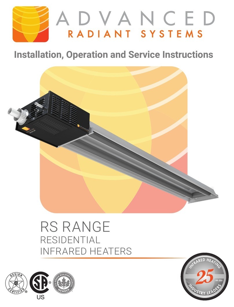
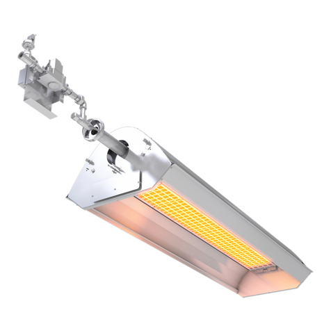
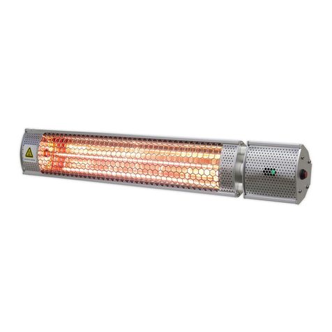
Advanced Radiant Systems ES/ESH Series Manual

Installation, Operation and Service Instructions
ES/ESH RANGE
SINGLE STAGE UNITARY
INFRARED HEATERS


WARNINGS
WARNING
Improper installation, adjustment, alteration, service
or maintenance can cause property damage, injury
or death. Read the installation, operating and
maintenance instructions thoroughly before
installing or servicing this equipment.
FOR YOUR SAFETY
Do not store or use gasoline or other flammable
vapors and liquids in the vicinity of this or any other
appliance. If you smell gas:
1. Open windows
2. Don’t touch electrical switches
3. Extinguish any open flame
4. Immediately call your gas supplier
OWNER
Retain this Manual & ensure available for service.
Improper installation, adjustment, alteration, service
or maintenance can cause injury, death or property
damage.
Read the installation, operation and service
instructions thoroughly before installing or servicing
this equipment.
INSTALLER
Provide Manual to Owner upon completion of
installation!
Read and thoroughly understand these Instructions
before attempting any installation
CAUTION: FIRE OR EXPLOSION HAZARD
Maintain clearance to combustible constructions as
further specified in this manual. Failure to do so
could result in a serious fire hazard. Heaters should
not be located in hazardous atmospheres containing
flammable vapors or combustible dusts. Signs
should be provided in storage areas specifying
maximum safe stacking height.
CAUTION: MECHANCIAL HAZARD
This equipment expands and contracts with each
operating cycle. The gas connection, suspension
hardware and the installation itself must safely allow
this movement. Failure to do so could result in
serious fire or explosion hazard.
CAUTION: FIRE OR EXPLOSION HAZARD
This heater is equipped with an automatic ignition
device. Do not attempt to light the burner by hand.
Failure to comply could result in a serious fire and
personal injury hazard.
CAUTION: MECHANCIAL HAZARD
Do not use high pressure (above 1/2 psi) to test the
gas supply system with the burners connected,
doing so could result in damage to the burner and
its control components requiring replacement.
Do not install equipment in atmospheres containing
halogenated hydrocarbons or other corrosive
chemicals, doing so may lead to premature
equipment failure and invalidation of the warranty.
Additionally, it is recommended that the equipment
be installed with a slope downward and away from
the burner of ¼" (6mm) in 10' (3m) to allow start-up
condensate drainage.
CAUTION: SERVICE LIFE RISK
Due to continuous product innovations, we reserve the right to change product specifications without due notice.

CONTENTS
INTRODUCTION ............................................................................................................................. 1
Installation Codes.............................................................................................................................................1
GENERAL SPECIFICATIONS.......................................................................................................... 2
Gas Supply ........................................................................................................................................................2
Electrical Supply ...............................................................................................................................................2
Flue and Outside Air Connection.....................................................................................................................2
DIMENSIONAL CHARTS ................................................................................................................ 3
CLEARANCE TO COMBUSTIBLES ................................................................................................. 6
INSTALLATION .............................................................................................................................. 9
Installation Sequence.......................................................................................................................................9
Hangers Installation and Heater Suspension...............................................................................................11
Tube Installation .............................................................................................................................................12
........................................................................................................................14
......................................................................................................................................15
Elbow and U-Bend Installation.......................................................................................................................18
........................................................................................................................19
................................................................................................................ 20
.............................................................................................................21
Decorative Grille (Optional)........................................................................................................................... 22
VENTING AND COMBUSTION AIR DUCTING .............................................................................. 23
.................................................................................................................................. 23
Un-Vented Operation..................................................................................................................................... 23
Horizontal Venting......................................................................................................................................... 24
Vertical Venting ............................................................................................................................................. 25
............................................................................................................................. 25
................................................................................................................ 26
Outdoor Installation (ESH Models Only)...................................................................................................... 26
GAS PIPING.................................................................................................................................. 27
.................................................................................................................................. 27
ELECTRICAL WIRING................................................................................................................... 27
.................................................................................................................................. 27
............................................................................................................................................ 28
.......................................................................................................... 29
BURNER OPERATION................................................................................................................... 30
Starting Sequence of Operation................................................................................................................... 30
Maintenance .................................................................................................................................................. 30
INSTALLATION CHECKLIST ........................................................................................................ 31
TROUBLESHOOTING ................................................................................................................... 32
Module Codes................................................................................................................................................ 32
.................................................................................................................................. 33
REPLACEMENT PARTS ............................................................................................................... 34
WARRANTY.................................................................................................................................. 35

Page 1
Single Stage Unitary Range ES/ESH-LT209_10152019
INTRODUCTION
Installation Codes
regulations and procedures as listed below.
General Installation and Gas Codes
Aircraft Hangar Installation
CSA B149.1 and B149.2 Installation Codes in Canada.
Gas Supply Lines
and CSA B149.1 and B149.2 Installation Codes in Canada.
Electrical
Venting
IMPORTANT
proceeding.

Page 2 ES/ESH-LT209_10152019Single Stage Unitary Range
GENERAL SPECIFICATIONS
Gas Supply
Inlet Pressure
Natural Gas: 5.0" W.C.
14.0" W.C.
11.5" W.C.
14.0" W.C.
Manifold Pressure
Natural Gas: 3.5" W. C.
10.5" W. C.
Inlet Connection
Natural Gas:
Electrical Supply
Flue and Outside Air Connection

Page 3
Single Stage Unitary Range ES/ESH-LT209_10152019
DIMENSIONAL CHARTS
18"
120"
24"
14"
15"
9"
6"
16"
36"
12"
12" 124"
BAFFLE SECTION
REFLECTOR
TUBE
4', 6' OR 8'
10' - 4"
10'
ELBOW
U-BEND
24"
16"
18"
BAFFLE SECTION
STANDARD
4" COUPLER
For additional information, including weights visit AdvancedRadiantSystems.com/Resources

Page 4 ES/ESH-LT209_10152019Single Stage Unitary Range
CONFIGURATIONS
MODEL NO. RATE
HEAT EXCHANGER LENGTH FT BAFFLE
ft BAFFLE KIT
PART NO.
MINIMUM MAXIMUM
ES/ESH-40 40,000 10 (3) 20 (6) 6 (1.8) T-CT045
ES/ESH-60* 60,000 20 (6) 30 (9) 6 (1.8) T-CT046
ES/ESH-80* 80,000 20 (6) 30 (9) 12 (3.6) T-CT047
ES/ESH-100* 100,000 20 (6) 30 (9) 12 (3.6) T-CT047
ES/ESH-125* 125,000 30 (9) 50 (12) 12 (3.6) T-CT047
ES/ESH-150* 150,000 40 (12) 60 (18) 6 (1.8) T-CT046
ES/ESH-175 175,000 50 (15) 60 (18)
ES/ESH-205* 205,000 60 (18) 70 (21) * *
ES/ESH-220 220,000 60 (18) 70 (21)
Note:
•
•
•
•
Bafe Kit Parts Reference
•
•
•
•
*Additional Approved Special Congurations
•
•
•
•
•
•
3'-6" 7'-6"
40'
50'
P/N T-CT026 P/N T-CT027
FOLD
OVER
FOLD
OVER
Baffle Kit P/N T-CT095

Page 5
Single Stage Unitary Range ES/ESH-LT209_10152019
CONFIGURATIONS
OVERLAP ADJACENT
REFLECTORS 4" TO 6"
AVAILABLE IN 40,000 BTU/HR
10'
15'
AVAILABLE IN 40,000/ 60,000 BTU/HR
20'
AVAILABLE IN 40,000/ 60,000/ 80,000/ 100,000 BTU/HR
30'
AVAILABLE IN 60,000/ 80,000/ 100,000/ 125,000 BTU/HR
40'
AVAILABLE IN 80,000/ 100,000/ 125,000/ 150,000 BTU/HR
50'
60'
70'
'U' TUBE CONFIGURATION
'L' CONFIGURATION
AVAILABLE IN 100,000/ 125,000/ 150,000/ 175,000/ 205,000 BTU/HR
AVAILABLE IN 150,000/ 175,000/ 205,000/ 220,000 BTU/HR
AVAILABLE IN 205,000/ 220,000 BTU/HR
LEGEND
BURNER COUPLING
REFLECTOR 10'-6" TYP.
TUBE 10' TYP.
'U' BEND ELBOW

Page 6 ES/ESH-LT209_10152019Single Stage Unitary Range
REFLECTOR CONFIGURATIONS MODEL
NUMBER
CLEARANCE TO COMBUSTIBLES in
A B C D
HORIZONTAL
ES/ESH-40 2 (5) 18 (46) 45 (114) 18 (46)
ES/ESH-60 2 (5) 25 (63) 58 (147) 25 (63)
ES/ESH-80 2 (5) 26 (66) 62 (157) 26 (66)
ES/ESH-100 2 (5) 30 (76) 67 (170) 30 (76)
ES/ESH-125 4 (10) 33 (84) 71 (180) 33 (84)
ES/ESH-150 4 (10) 36 (91) 74 (188) 36 (91)
ES/ESH-175 6 (15) 40 (102) 78 (198) 40 (102)
ES/ESH-205 6 (15) 44 (46) 80 (203) 44 (46)
ES/ESH-220 6 (15) 46 (117) 83 (211) 46 (117)
CLEARANCE TO COMBUSTIBLES
A general clearance of 18" (46 cm) in every direction
WARNING
◊Clearances as marked on the heater body must be maintained from vehicles parked beneath. Signs should be
posted identifying any possible violation of the clearance distances from the heater in all vehicle areas.
◊Maximumallowablestackingheightinstorageareasshouldbeidentiedwithsignsorappropriatemarkings
adjacent to the thermostat or in a conspicuous location.
standard clearances also apply to installation above T-bar ceilings and above decorative grilles. Additional
Combustible materials are considered to be wood, compressed paper, plant bers, plastics, Plexiglas or other
materials capable of being ignited and burned. Such materials shall be considered combustible even though
ameproofed, re-retardant treated or plastered.
◊Note 1: Bottom Shields are approved for all burner sizes. The “below” clearance (dimension C in Table 2) may
be reduced by 25% when an approved Bottom Shield is used.
◊Note2:Reducedclearancesdownstreamfromtheburnerareapprovedforallcongurations.DimensionsB,
C,andDinTable2canbereducedforlocations25'(7.6m)ormoredownstreamfromaburner,beforethe
nextburner,maximumreductionis50%

Page7
Single Stage Unitary Range ES/ESH-LT209_10152019
CLEARANCE TO COMBUSTIBLES
REFLECTOR CONFIGURATIONS MODEL
NUMBER
CLEARANCE TO COMBUSTIBLES in
A B C D
45° REFLECTOR TILT
ES/ESH-40 4 (10) 4 (10) 40 (102) 38 (97)
ES/ESH-60 4 (10) 4 (10) 50 (127) 46 (117)
ES/ESH-80 4 (10) 4 (10) 58 (147) 50 (127)
ES/ESH-100 4 (10) 4 (10) 67 (170) 58 (147)
ES/ESH-125 4 (10) 4 (10) 70 (178) 63 (160)
ES/ESH-150 4 (10) 4 (10) 71 (180) 64 (163)
ES/ESH-175 8 (20) 4 (10) 74 (188) 67 (170)
ES/ESH-205 8 (20) 4 (10) 78 (198) 72 (183)
ES/ESH-220 8 (20) 4 (10) 81 (205) 77 (196)
ONE SIDE EXTENSION MODEL NO. A B C D
ES/ESH-40 2 (5) 4 (10) 50 (127) 35 (89)
ES/ESH-60 2 (5) 4 (10) 58 (147) 38 (97)
ES/ESH-80 2 (5) 4 (10) 63 (160) 42 (107)
ES/ESH-100 2 (5) 4 (10) 73 (185) 45 (114)
ES/ESH-125 4 (10) 4 (10) 76 (193) 50 (127)
ES/ESH-150 4 (10) 4 (10) 78 (198) 52 (132)
ES/ESH-175 6 (15) 6 (15) 80 (203) 54 (137)
ES/ESH-205 6 (15) 6 (15) 84 (213) 56 (142)
ES/ESH-220 6 (15) 6 (15) 84 (213) 58 (147)
TWO SIDE EXTENSIONS MODEL NO. A B C D
ES/ESH-40 2 (5) 9 (23) 50 (127) 9 (23)
ES/ESH-60 2 (5) 16 (41) 58 (147) 16 (41)
ES/ESH-80 2 (5) 18 (46) 64 (163) 18 (46)
ES/ESH-100 4 (10) 18 (46) 71 (180) 18 (46)
ES/ESH-125 4 (10) 22 (56) 78 (198) 22 (56)
ES/ESH-150 4 (10) 24 (64) 80 (203) 25 (64)
ES/ESH-175 6 (15) 26 (66) 82 (208) 26 (66)
ES/ESH-205 6 (15) 29 (74) 86 (218) 29 (74)
ES/ESH-220 6 (15) 31 (79) 88 (224) 31 (79)

Page 8 ES/ESH-LT209_10152019Single Stage Unitary Range
REFLECTOR CONFIGURATIONS MODEL
NUMBER
CLEARANCE TO COMBUSTIBLES in
A B C D
U-BEND, HORIZONTAL
ES/ESH-40 ----
ES/ESH-60 2 (5) 25 (63) 59 (150) 22 (56)
ES/ESH-80 2 (5) 28 (71) 62 (157) 26 (66)
ES/ESH-100 2 (5) 30 (76) 71 (180) 30 (76)
ES/ESH-125 4 (10) 34 (86 74 (188) 33 (66)
ES/ESH-150 4 (10) 37 (94) 76 (193) 36 (84)
ES/ESH-175 6 (15) 40 (102) 78 (198) 40 (102)
ES/ESH-205 6 (15) 45 (114) 82 (208) 4 4 (112)
ES/ESH-220 6 (15) 46 (117) 88 (224) 46 (117)
CLEARANCE TO COMBUSTIBLES
MODEL NO. UN-VENTED FLUE IN VENTED FLUE in
ABOVE END END
ES/ESH-40 12 (30) 26 (66) 18 (46)
ES/ESH-60 12 (30) 26 (66) 18 (46)
ES/ESH-80 18 (46) 26 (66) 18 (46)
ES/ESH-100 18 (46) 26 (66) 18 (46)
ES/ESH-125 18 (46) 26 (66) 18 (46)
ES/ESH-150 18 (46) 32 (81) 18 (46)
ES/ESH-175 18 (46) 32 (81) 18 (46)
ES/ESH-205 18 (46) 32 (81) 18 (46)
ES/ESH-220 18 (46) 32 (81) 18 (46)
*Note: All dimensions shown are measured from outside surface of all tubes, reectors and ttings.
U-BEND, OPPOSITE 45° MODEL NO. A B C D
ES/ESH-40 ----
ES/ESH-60 4 (10) 46 (117) 51 (129) 16 (41)
ES/ESH-80 4 (10) 50 (127) 54 (137) 18 (46)
ES/ESH-100 4 (10) 54 (137) 64 (163) 18 (46)
ES/ESH-125 4 (10) 63 (160) 69 (175) 22 (56)
ES/ESH-150 4 (10) 64 (163) 71 (180) 24 (64)
ES/ESH-175 8 (20) 67 (170) 74 (188) 26 (66)
ES/ESH-205 10 (25) 72 (183) 78 (198) 29 (74)
ES/ESH-220 10 (25) 74 (188) 81 (206) 32 (81)
For additional information, including mounting heights visit AdvancedRadiantSystems.com/Resources

Page 9
Single Stage Unitary Range ES/ESH-LT209_10152019
INSTALLATION
Installation Sequence
A general ordered sequence for installation follows for reference.
Note:
REFLECTOR
OVERLAP APPROX. 8"
REFLECTOR
END CAP
ADJUSTABLE
VENT ADAPTER
(S-20 AND LONGER)
LOOSE
SCREWS
ADJUSTABLE VENT ADAPTER
(S-20 AND LONGER) TIGHT FASTEN END CAP
WITH SCREWS
SCREWS
LOOSE
SCREWS
BEND TAB
OVER END
OF TUBE TIGHT
SCREWS
**INSTALL
BAFFLE(S) AS
REQUIRED IN THE
LAST SECTION OF
TUBE OR AS
SPECIFIED IN THE
MANUAL
CLOSE ALL OPEN ENDED
"S" HOOKS, CHAIN LINKS,
AND TURNBUCKLES OR
ANY OPEN CONNECTION.
HEAT INSTALL "J"
EXCHANGER BOLT AT FIRST
TUBE HANGER
TUBE TUBE FLANGE
COUPLING
COMBUSTION
TUBE
COUPLING INSTALLATION
MOVING BETWEEN THE FOUR BOLTS,
TIGHTEN EACH, ENSURING THAT EQUAL
PRESSURE IS APPLIED TO EACH SET PIN
IN TURN.
IMPORTANT: COMPLETE ASSEMBLY BY DRILLING AND
SCREWING SELF TAPPING RETENTION ZIP SCREWS.
GASKET
BURNER ASSEMBLY
3" - 6"
Figure 5: General Overview of Installation

Page10 ES/ESH-LT209_10152019Single Stage Unitary Range
INSTALLATION
Overview of Tubes and Reector Hangers
3"-6"
COMBUSTION
TUBE
TUBE
COUPLING
TUBE
COUPLING
HEAT
EXCHANGER
TUBE
GASKET
TUBE
FLANGE
INSTALL "J"
BOLT AT FIRST
HANGER
BURNER ASSEMBLY
NOTE: CLOSE ALL OPEN ENDED "S" HOOKS, CHAIN LINKS, AND
TURNBUCKLES OR ANY OPEN CONNECTION.
**INSTALL
BAFFLE(S) AS
REQUIRED IN THE
LAST SECTION OF
TUBE OR AS
SPECIFIED IN THE
MANUAL
BEND TAB
OVER END
OF TUBE
ADJUSTABLE VENT ADAPTER
(S-20 AND LONGER)
LOCATE TUBE AND REFLECTOR HANGERS
EVERY 10' THEREAFTER.
10' FLANGED
TUBE
10' TUBE
10' TUBE
*NOTE: 30' SYSTEM SHOWN HERE, THE SAME PRINCIPLE
SHOULD BE FOLLOWED FOR 40', 50' SYSTEMS OR MORE.
REFER TO INSTALLATION SEQUENCE FOR MORE
DETAILS.
8' - 9'
IMPORTANT: COMPLETE ASSEMBLY BY DRILLING AND
SCREWING SELF TAPPING RETENTION ZIP SCREWS.

Page 11
Single Stage Unitary Range ES/ESH-LT209_10152019
INSTALLATION
Hangers Installation and Heater Suspension
•
contact.
•
•
and Figure 8.
I-BEAM
I-BEAM
CONCRETE BEAM
TRUSS
24" MIN.
BEAM
CLAMP
THREADED
ROD
TURNBUCKLE
NOTE: CLOSE
ALL QUICK LINKS,
“S” HOOKS CHAIN
LINKS, “J” BOLTS,
TURNBUCKLES,
OR ANY OPEN
CONNECTION.
ANCHOR
CHAIN LINK
12" MIN.
12" MIN.
EYE BOLT
³/8"
10'
10'
8' TO 9'
CLOSE ALL OPEN ENDED
QUICK LINKS OR "S"
HOOKS, CHAIN LINKS
AND TURNBUCKLES OR
ANY OPEN CONNECTION BURNER SIDE
"FIRST HANGER"
VENTING SIDE
"LAST HANGER"

Page 12 ES/ESH-LT209_10152019Single Stage Unitary Range
INSTALLATION
Tube Installation
•
•
Figure 9: Installation of First Section of Flanged Tube
COUPLING SHOULD
BE LOOSELY FITTED
10'
8' - 9'
10'
3" - 6"
COMBUSTION
TUBE
TUBE & REFLECTOR
HANGERS
LOCATE TUBE AND
REFLECTOR
HANGERS EVERY
10' THEREAFTER.
NOTE: CLOSE ALL OPEN-ENDED QUICK LINKS, CHAIN
LINKS,AND TURNBUCKLES OR ANY OPEN CONNECTION.
INSTALL "J" BOLT
AT FIRST HANGER
TUBE FLANGE
TUBE WELD SEAM
FACING DOWN
•
10'
COUPLING
SHOULD BE
LOOSELY
FITTED
HEAT
EXCHANGER
TUBE
CLOSE ALL OPEN ENDED
"S" HOOKS, CHAIN LINKS,
AND TURNBUCKLES OR
ANY OPEN CONNECTION.
TUBE
WELD
SEAM
FACING
DOWN

Page 13
Single Stage Unitary Range ES/ESH-LT209_10152019
INSTALLATION
•
•Note:
ALL tubes is facing down.
•Note:
coupler (refer to Figure 11).
DO NOT over torque the coupling. (Torque coupling to 15-25 lbf-ft).
TORQUE TO 15-25 FT.-LBS
WHEN INSTALLING,
ORIENT COUPLING
LOCK BOLTS TO TOP,
AT 10 O'CLOCKOR 2
O'CLOCK POSITION TO
AVOID CONTACT WITH
THE REFLECTOR
REFLECTOR
HANGER
INSTALLATION OF REFLECTOR HANGERS
AND "J" BOLT
TUBE
WELD
SEAM
TUBE
WELD
SEAM
PLACE TUBE IN THE
REFLECTOR HANGER AS
SHOWN
INSTALL "J" BOLT
TO TIGHTEN
CRADLE LOOP AT
FIRST HANGER
ONLY
COUPLING INSTALLATION
MOVING BETWEEN THE
FOUR BOLTS, TIGHTEN
EACH, ENSURING THAT
EQUAL PRESSURE IS
APPLIED TO EACH SET PIN
IN TURN.
INSTALLATION OF TUBE COUPLING
IMPORTANT: COMPLETE ASSEMBLY BY DRILLING AND
SCREWING SELF TAPPING RETENTION ZIP SCREWS.
•
Note:

Page 14 ES/ESH-LT209_10152019Single Stage Unitary Range
INSTALLATION
Heater and Bafe Installation
•
The burner must never be installed in a tilted position.
TUBE FLANGE
GASKET
NOTE: CLOSE ALL OPEN ENDED "S" HOOKS, CHAIN LINKS,
AND TURNBUCKLES OR ANY OPEN CONNECTION.
NOTE: BURNER MUST
NEVER BE TILTED
SIDEWAYS. ONLY
INSTALL AS SHOWN.
BURNER
ASSEMBLY
•
•Note:
•Note:
tube using a long wire.
VENT
ADAPTER
INSTALL BAFFLE AS
REQUIRED IN LAST
SECTION OF TUBE
BEND TAB
OVER END
OF TUBE AT
6 O’CLOCK
POSITION
NOTE: CLOSE ALL OPEN ENDED "S" HOOKS, CHAIN LINKS,
AND TURNBUCKLES OR ANY OPEN CONNECTION.

Page 15
Single Stage Unitary Range ES/ESH-LT209_10152019
INSTALLATION
Reector Installation
•
SLIDE REFLECTOR THROUGH
THE HANGER AND REFLECTOR
SUPPORT AS SHOWN
NOTE: CLOSE ALL OPEN-ENDED QUICK LINKS, CHAIN
LINKS,AND TURNBUCKLES OR ANY OPEN CONNECTION.
•
TUBE
SPRING CLIP
REFLECTOR BRACKET
REFLECTOR BRACKET
REFLECTOR SUPPORT BRACKET INSTALLATION
1. PLACE REFLECTOR BRACKET UNDERNEATH
THE TUBE.
2.HOOK THE SPRING CLIP WITH THE REFLECTOR
BRACKET AND ROTATE OVER THE TUBE.
3.PUSH DOWN THE SPRING CLIP AND SLIDE
UNDERNEATH THE REFLECTOR BRACKET.

Page 16 ES/ESH-LT209_10152019Single Stage Unitary Range
INSTALLATION
Note:
to Figure 16..
HEATER END
VENT
TERMINATION
END
FASTEN ENDCAP
WITH SCREWS
TIGHT
SCREWS
LOOSE
SCREWS
LOOSE
SCREWS
REFLECTOR
SUPPORT
TIGHT
SCREWS
VENT
TERMINATION
END
REFLECTOR
SUPPORT
LOOSE
SCREWS
TIGHT
SCREWS
LOOSE
SCREWS
TIGHT
SCREWS
FASTEN ENDCAP
WITH SCREWS
REFLECTOR OVERLAP
APPROX. 6"
HEATER END
NOTE:
DO NOT ALLOW
TIGHTENED SCREWS TO
PENETRATE REFLECTORS
REFLECTOR OVERLAP ILLUSTRATION
REFLECTOR
OVERLAP
APPROX. 6"
NOTE: DO NOT ALLOW TIGHTENED
SCREWS TO PENETRATE REFLECTORS
This manual suits for next models
9
Table of contents
Other Advanced Radiant Systems Heater manuals
Popular Heater manuals by other brands

Trane
Trane UniTrane Fan-Coil Installation operation & maintenance

Fantech
Fantech AS 4000 Operating instructions & installation manual

bathstore
bathstore Rimini 43100001650 Installation instruction
Soleus Air
Soleus Air HR1-08R-21 operating instructions

ALPENHEAT
ALPENHEAT Feater instructions
Reer
Reer FeelWell Instructions for use
