Austria Email EBH-KDW Service manual
EBH-KDW
EBH-TDW
Operating and Mounting Instructions
Please pass on to the user!
Id.Nr.: 228557-15

2
Id.Nr.: 228557-15
Dear customer!
The built-in electric heaters are manufactured in accordance with the applicable regulations.
The installation and first commissioning must be performed by a licensed plumber and in accordance with these instructions
only.
You will find all important information for correct assembly and operation of the built-in heater in this small brochure. Ne-
vertheless, let your concessionary demonstrate to you how to operate the device and explain its function after completed
installation.
Of course, our customer service and sales department are readily available to support you in case you need any advice.
Enjoy the use of your built-in electric heater.
TABLE OF CONTENTS.........................................................................................................................................................Page
Safety instructions...................................................................................................................................... 3
1. Function..................................................................................................................................................... 4
2. Energy Saving.......................................................................................................................................... 4
3. Operation and Temperature Setting ............................................................................................... 4
4. Operating Requirements..................................................................................................................... 4
5. Information for Assembly and Installation.................................................................................... 5
5.1 General Information for Installation....................................................................................................... 5
5.2 Assembly of Built-in Heater....................................................................................................................... 6
5.3 Information on Corrosion Protection..................................................................................................... 6
5.4 Water Connection of Tank .......................................................................................................................... 7
5.5 Electrical Connection................................................................................................................................... 7
5.6 Circuit Diagrams ............................................................................................................................................ 8
5.7 First Commissioning....................................................................................................................................12
6. Inspection, Maintenance, Service....................................................................................................12
7. Malfunctions ...........................................................................................................................................12
8. Recycling and disposal........................................................................................................................12
Warranty, Guarantee and Product Liability ......................................................................................13

Id.Nr.: 228557-15
3
SAFETY INSTRUCTIONS
General
• This immersion heater can be used by children eight years old and older as well as by persons
with reduced physical, sensory or mental capabilities or who lack experience and knowledge
if they are supervised or if they have been trained with regard to the safe use of the immersion
heater and understand the resulting risks. Children may not play with the immersion heater or its
packaging. Cleaning and user maintenance may not be performed by children without supervi-
sion.
• The immersion heater may only be installed and operated as described in this manual or the
associated technical information. Any other use is not proper and is therefore impermissible.
• A defective immersion heater may not continue to be operated.
• There is a risk of scalding from hot water or hot components (e.g. ttings, hot water outlet pipe,
etc.).
• The immersion heater is not suitable for operation in aggressive media (alcohol, glycol, oil, ba-
ses, acids, etc.).
• When using an electric immersion heater, proper corrosion protection is to be ensured.
• Only use original accessories or original spare parts from the manufacturer.
Installation and commissioning
• Installation and commissioning may only be performed by qualied specialised personnel who
therefore assume the responsibility for the proper assembly according to the applicable laws,
standards and guidelines.
• The immersion heater may only be installed in dry, freeze-protected spaces.
• The data specied on the nameplate (immersion heater as well as tank) must be observed.
• Prior to the commissioning of the immersion heater, the heating rods must be completely sur-
rounded by water.
Electrical Connection
• Only qualied specialised personnel may connect the immersion heater to xed lines while ob-
serving the relevant professional standards and laws.
• A ground fault circuit interrupter with a trip current of I∆n ≤ 30mA must be installed upstream
from the electrical circuit.
• The electrical connection is to be carried out exclusively according to the connection diagram
adhered to the inside of the protective cap!
• Before working on the immersion heater, this is to be de-energised, checked for the absence of
voltage and secured against being switched on again.
• If a connection cable is damaged, immediately unplug the power plug and call a professional!
• Connection cables may not be extended or cut through in any way.
• ATTENTION: The factory wiring must not be altered!
Servicing
• Maintenance, cleaning and any necessary repair or service work may only be performed by spe-
cialised personnel who are qualied for this purpose.
• Never try to x errors and faults yourself.
• Necessary service and maintenance intervals are to be observed in accordance with these ope-
rating and assembly instructions.

4
Id.Nr.: 228557-15
1. FUNCTION
The electric built-in heaters are service and maintenance-free as the main heating unit for electrically heated hot
water tanks. Only in the case of heavily calciferous water it may be necessary to free the heating units from boiler
scale in certain intervals.
The desired temperature can be selected by the user on the control toggle. The heating is switched on automa-
tically by the temperature control, during the heating period determined by the relevant ESC, and off again when
the desired tank water temperature is reached. If the water temperature drops, e.g. by the withdrawal of water
or natural cooling-off, then the device heating switches on again until the pre-selected tank water temperature
is reached.
2. ENERGY SAVING
Low tank water temperatures prove to be particularly economical. Therefore, the progressively adjustable temperature
should only be selected as high as necessary for the actual hot water demand. This helps to save electricity and reduces
furring in the tank.
3. OPERATION AND TEMPERATURE SETTING
The tank water temperature can be set progressively using the temperature selector or by the four indicated main grades
in accordance with your hot water demand. This way, an energy-conscious operation of the built-in heater is possible:
As a setting aid, the toggle of the electric heater’s temperature control has 4 indicated main stages, namely:
Position: frost protection for the tank (up to 30 °C)
Position: approx. 40°C, hand warm tank water
Position: •• approx. 65°C, moderately hot tank water
This position is recommended to rule out unintentional scalding by excessively hot water.
The device operates particularly economically in this setting.
The heat losses are minor and the formation of boiler scale is largely avoided.
Low standby energy consumption.
Position: ••• approx. 75°C, hot storage water, (temperature controller up to 80°C optionally available)
Caution:
Control toggle at left limit stop does not result in an off position or shutdown of the device heating.
The temperature control should not be set higher than the position •• (approx. 65°C) when operated using day current.
Due to the hysteresis of the temperature control (± 7°K) and possible radiation losses (cooling-down of the pipelines), the
temperature specifications are subject to an accuracy of ± 10°K.
4. OPERATING REQUIREMENTS
The built-in heating must be used exclusively in accordance with the requirements (operating pressure, heating time, supply
voltage, etc.) specified on the rating plate. The power connection must be performed in accordance with the connection
diagram affixed to the inside of the protective cap.
In addition to the legally approved national regulations (ÖVE, VDE, ÖNORM or DIN, etc.), the connecting requirements of
the local power company and waterworks as well as the Assembly and Operating Instructions must also be complied with.
In the case of heavily calciferous water, we recommend the upstream integration of a customary antiliming device.
This built-in heater is particularly suitable for installation in enamelled free-standing tanks as well as double shell units.
Due to the special design, however, these units may also be installed in foreign makes with enamelled, plastic-coated or
hot-dip galvanised boilers. A combination with CrNi (NIRO) boilers is problematic and therefore not recommended (for
necessary measures see section 5.3).
For the purpose of installation in enamelled boilers, our built-in heaters, screw-mounted heating units and built-in finned
tube heat exchangers are designed using structurally isolated heating units in conjunction with a guard circuit shunt resistor
and are therefore in compliance with the state of the art, particularly with regard to the corrosion protection of enamelled
boilers. All heating installations are suitable for pressure-proof operation and the heating up of drinking or heating water up
to a maximum operating pressure of 10 bar.
This device is not designed to be used by persons (including children) with physical, sensory or mental disabilities or lacking
experience and/or lacking knowledge, unless these are supervised by a person who is responsible for their safety or have
received instructions on how to use this device from any such person. Children should be supervised in order to ensure
that they do not play with this device.
Built-in heating systems are not suitable for use in aggressive media (alcohol, glycol, oil, etc.)!
Id.Nr.: 228557-15
5
Should a device, at the point of delivery, clearly display a malfunction, damage or other defect, this must not be fitted, installed
or used in the system. Subsequent complaints regarding devices with an obvious defect which have been connected and in-
stalled are expressly excluded under the warranty and guarantee.
5. INFORMATION FOR ASSEMBLY AND INSTALLATION
5.1 General Information for Installation
The heating unit and the sensor protection tube must be surrounded completely by sufficient water during operation. The
thermally-induced flow of water must not be obstructed.
The built-in heater is equipped with a safety temperature limiter, which stops any further heating of the device from a water
temperature of max. 110°C (EN 60335 -2-21; ÖVE-EW41, Part 2 (500) / 1971). Therefore, the connecting components
(connecting pipes, safety valve combinations, etc.) must be selected in such a way that they resist temperatures of 110°C
and any consequential damages are avoided in the event of any malfunction of the temperature control.
Assembly and installation must be performed exclusively by licensed craftsmen.
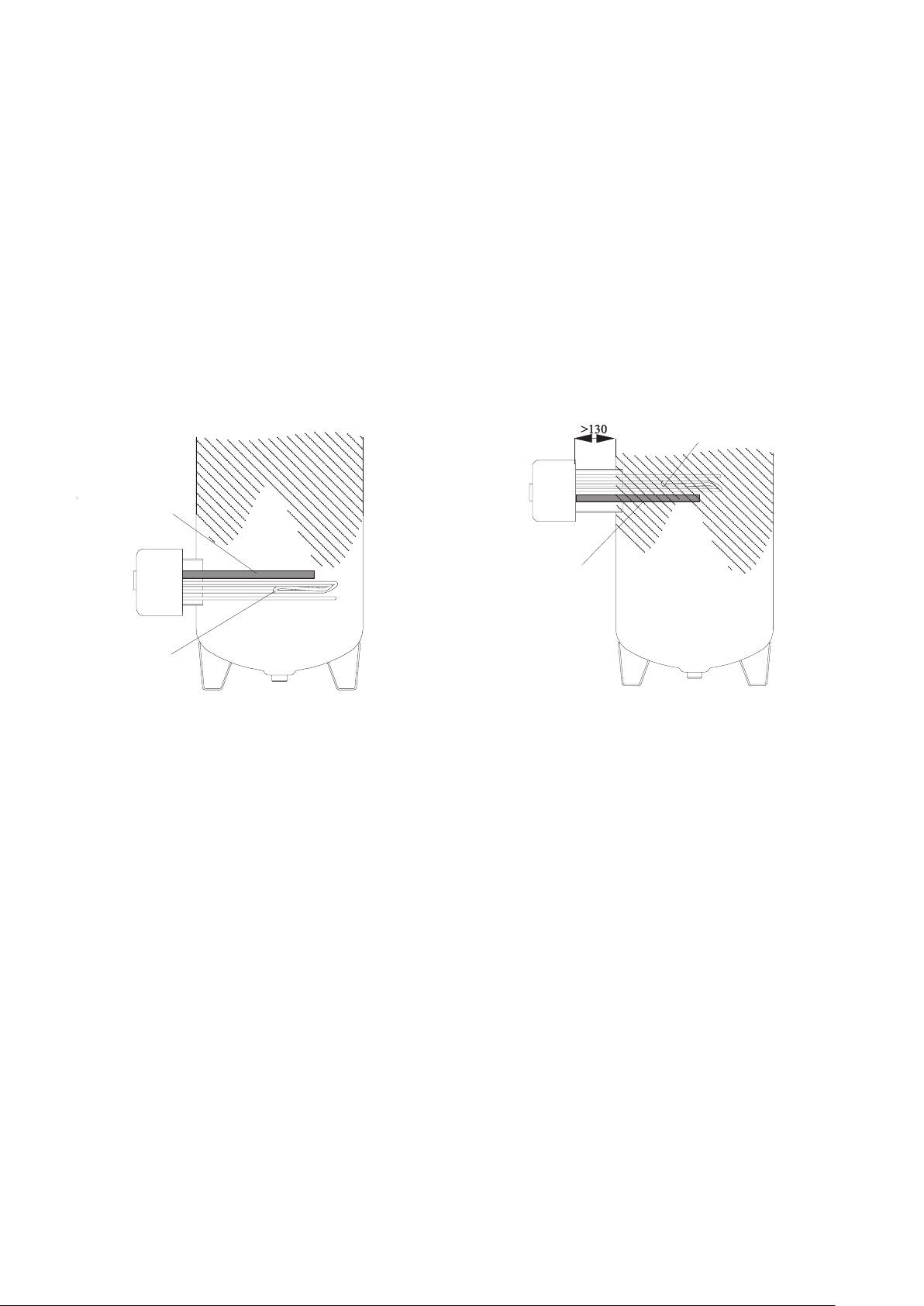
Fitting position:
The flange must not be longer than max. 130 mm, so that the thermometer and the heating unit still project into the hot
water tank sufficiently.
The built-in heating unit must be installed as far down as possible in the boiler, in order to heat up the entire boiler contents
equally. Thereby, it is not of importance whether the heating elements reach across the full fitting depth available.
Space must be kept free in front of the boiler flange (fitting length + 100 mm) for assembly, etc.
The function is impaired by the formation of boiler scale. Appropriate measures must be taken in the case of heavily calci-
ferous water: e.g. lowering of temperature, installation of a softening system, removal of the boiler scale.
Flange frame too long and wel-
ded-in too high.
Temperature control below hea-
ting unit.
CORRECT WRONG
Heating unit
Heating unit
COLD ZONE COLD ZONE
Temperature
control
6
Id.Nr.: 228557-15
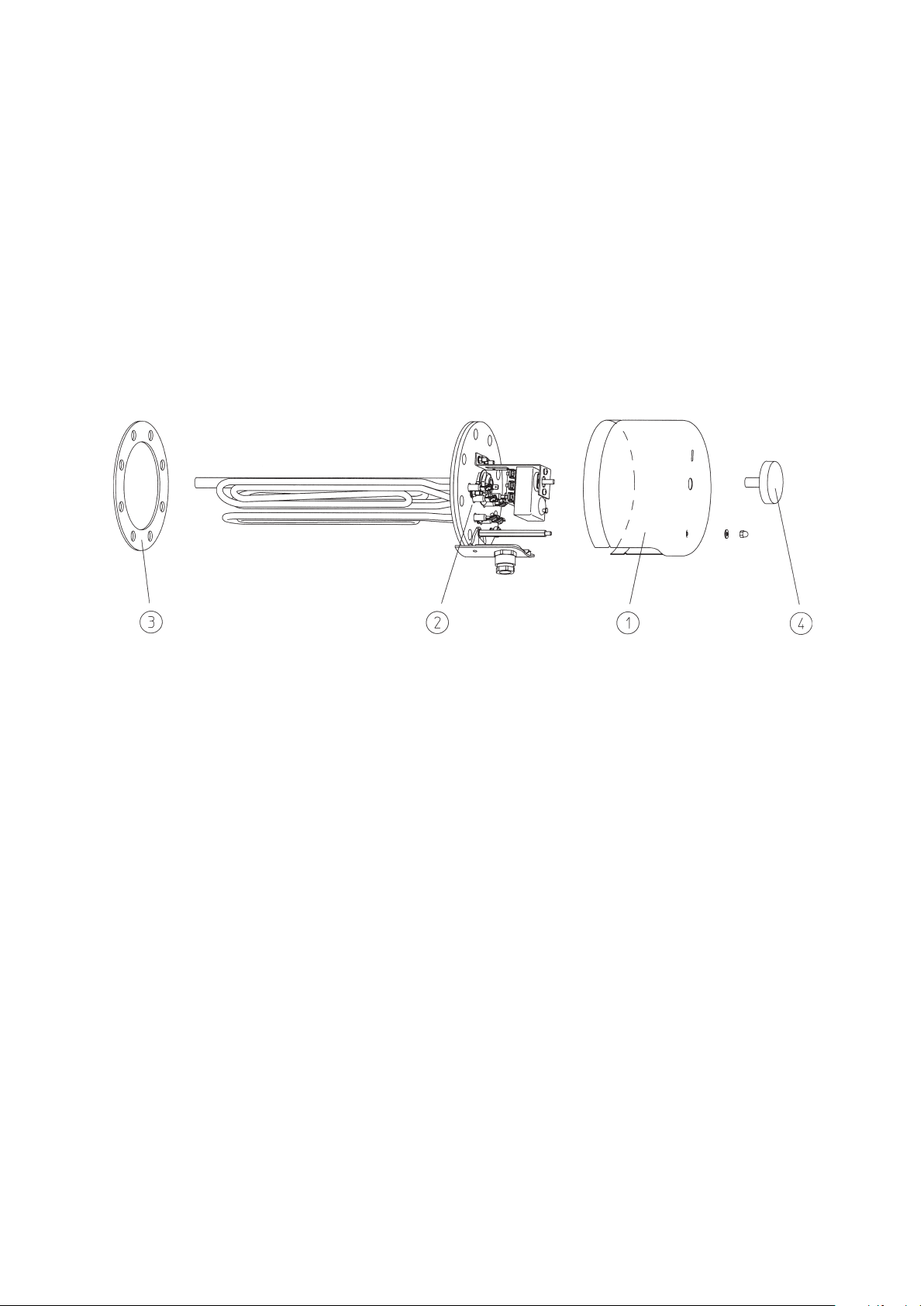
5.2 Assembly of Built-in Heater
In addition to the legally approved regulations, the connecting requirements of the local power company and waterworks
must be complied with.
1. Remove cover on tank.
2. Install heating flange “item 2”in boiler using sealing ring “item 3”.
The sensor protection tube of the temperature control must be located above the tubular heating unit(s) when
installed (see information for installation).
3. Attach the heating flange“item 2”using flange screws M12 (max. turning moment 25 Nm ±5).
Tighten the flange screws crosswise.
The screwed connection of the heating unit must be checked and retightened using a turning moment of 2-3
Nm, if necessary.
4. Produce power connection according to the circuit diagram (see section 5.5).
Important – do not forget: connect protective conductor!
5. Mount covering cap “item 1” on tank. Put on enclosed control toggle “item 4”, set desired service water tem-
perature.
6. Do not put into operation until the tank is filled with water.
The assembly of the heating installation and the initial start-up must be performed exclusively by an expert, who thereby
accepts responsibility for proper implementation and equipping.
5.3 Information on Corrosion Protection
The built-in heater is designed for installation in enamelled tanks. If the heater is installed in foreign makes, then the supplier
of the boiler must ensure sufficient corrosion protection. First control of the anode is after approx. 2 years operating time.
The protective anodes should be replaced if more than 3/4 of the material have degraded.
The following measure is required in the event of a combination with CrNi (NIRO) tanks or CrNi heat exchangers and instal-
lations in plastic-coated tanks:
a) Disconnect the guard circuit shunt resistor to ensure insulated installation of the heating unit.
b) Disconnect the anode - ground connection cable for the types with anode.
c) Replace the brass sensor tube with a stainless steel sensor tube.
Id.Nr.: 228557-15
7
5.4 Water Connection of Tank
It is imperative that the mounting, connecting and operating instructions of the hot water tank (boiler) are complied with.
Pressure-proof connection:
Any warranty shall be rejected in the case that unsuitable or inoperative tank connector fittings are used as well as in the
event of any exceedance of the specified operating pressure.
The plumbing must be performed exclusively using a design certified diaphragm safety valve or a combined diaphragm
safety valve connector fitting for pressure-proof storage tanks!
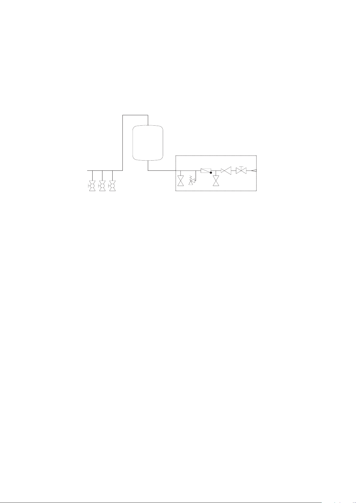
A safety valve combination (see “Tank connection pursuant to DIN 1988”) is installed in the cold water supply line (blue) of
the tank in the order as drawn.
5.5 Electrical Connection
The connection with the power grid must be implemented in conformity with the applicable national regulations and stan-
dards, the relevant connecting requirements of the local power company and waterworks, as well as the standards of the
Mounting and Operating Instructions, and must be performed exclusively by a licensed electrician. The stipulated protective
measures must be executed carefully, so that no other power-supplied devices are affected thereby in the event of a mal-
function or failure of the hot water tank’s power supply (e.g. freezer, rooms used for medical purposes, units for intensive
care, etc.).
In rooms with bathtubs or showers, the device must be installed in accordance with the national laws and regulations (e.g.
of ÖVE-SEV, VDE or DIN VDE 0100-701).
The technical connecting requirements (TAB) of the relevant energy supply company must absolutely be observed.
A residual current circuit breaker with a tripping current I∆N≤30mA must be connected in series before the electric circuit.
The device must only be connected with permanently laid lines.
These types of water heaters are to be supplied exclusively via a hard-wired connection cable and are therefore not suitable
for connection via a shock-proof plug (SKI). Accidental activation of the upstream RCD is to be avoided in this way.
An all-pole disconnecting unit with at least 3mm contact clearance must be connected in series before the device. This
requirement is fulfilled e.g. by an automatic cutout.
It is imperative that the hot water tank is filled with water prior to electrical start-up.
In accordance with the safety regulations, the hot water tank must be switched powerless, secured against being switched
on again and checked for powerlessness prior to any intervention. Interventions to the electrics of the device must only be
performed by a licensed electrician.
As a rule, the electrical connection must be performed in accordance with the circuit diagram affixed inside the connecting
area of the tank!
Tank
Safety valve
Waste valve
Non-return valve
Test valve
Pressure r
educing valve
Shut-off valve
Service water fixtures
8
Id.Nr.: 228557-15
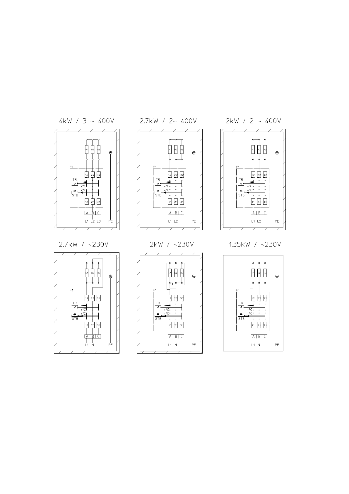
5.6 Circuit Diagrams
EBH-KDW1 4,0kW
EBH-TDW1 4,0 kW
Heating elements
3 x 1,35 kW / 230 V
3 x 40 Ohm
Circuit in factory conguration
4,0 kW / 3~400V
200 litres
4 hrs. / 4,0 kW
6 hrs. / 2,7 kW
8 hrs. / 2,0 kW
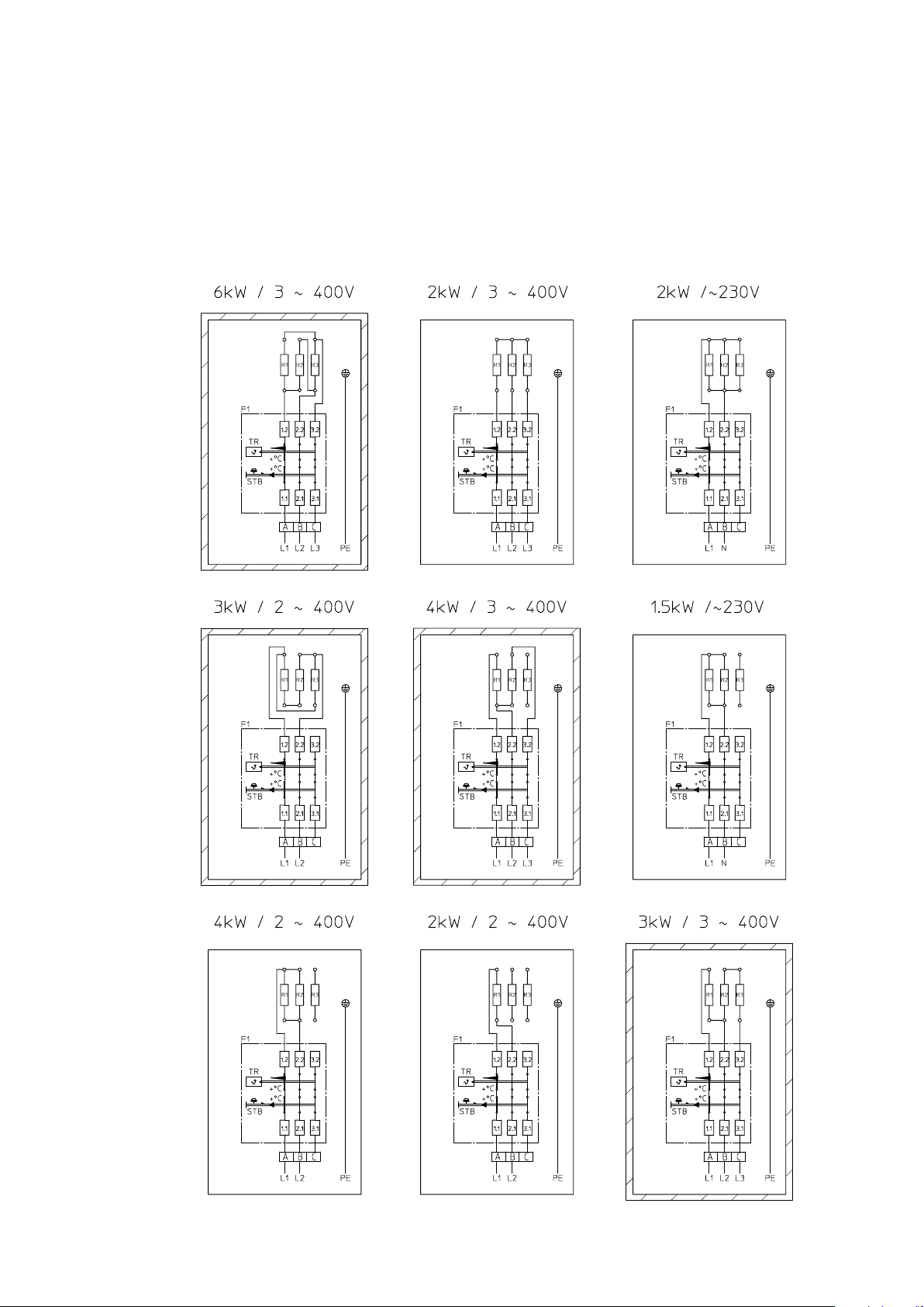
EBH-KDW1 6,0kW
EBH-TDW1 6,0 kW
Heating elements
3 x 2,0 kW / 400 V
3 x 80 Ohm
Circuit in factory conguration
6,0 kW / 3~400V
300 litres
4 hrs. / 6,0 kW
6 hrs. / 4,0 kW
8 hrs. / 3,0 kW
Id.Nr.: 228557-15
9
5.6 Circuit Diagrams
EBH-KDW1 4,0kW
EBH-TDW1 4,0 kW
Heating elements
3 x 1,35 kW / 230 V
3 x 40 Ohm
Circuit in factory conguration
4,0 kW / 3~400V
200 litres
4 hrs. / 4,0 kW
6 hrs. / 2,7 kW
8 hrs. / 2,0 kW
EBH-KDW1 6,0kW
EBH-TDW1 6,0 kW
Heating elements
3 x 2,0 kW / 400 V
3 x 80 Ohm
Circuit in factory conguration
6,0 kW / 3~400V
300 litres
4 hrs. / 6,0 kW
6 hrs. / 4,0 kW
8 hrs. / 3,0 kW

10
Id.Nr.: 228557-15
EBH-KDW1 8,0kW
EBH-TDW1 8,0 kW
Heating elements
3 x 2,7 kW / 400 V
3 x 60 Ohm
Circuit in factory conguration
8,0 kW / 3~400V
400 litres
4 hrs. / 8,0 kW
6 hrs. / 5,0 kW
8 hrs. / 4,0 kW

Id.Nr.: 228557-15
11
EBH-KDW1 10,0kW
EBH-TDW1 10,0 kW
Heating elements
3 x 3,3 kW / 400 V
3 x 48 Ohm
Circuit in factory conguration
10,0 kW / 3~400V
500 litres
4 hrs. / 10,0 kW
6 hrs. / 6,5 kW
8 hrs. / 5,0 kW

12
Id.Nr.: 228557-15
5.7 First Commissioning
The tank must be filled with water before switching on the electricity.
The expansion water created in the internal boiler during the heating process must drip from the safety valve in the case of a
pressure-proof connection, and from the overflow mixing tap in the case of an unpressurised connection.
The entire initial heating process is to be monitored, from cold water to reaching the set temperature. This will allow possible
defective connections to the electric immersion heater to be detected immediately and other damages resulting from this can be
avoided in time!
Caution: the hot water drain pipe as well as parts of the safety fitting may become hot.
The preset temperature, the actual temperature of the water withdrawn and the hot water quantity display should correspond
approximately after completion of the heating process.
6. INSPECTION, MAINTENANCE, SERVICE
The boiler scale as well as the furring that forms in the internal boiler of the storage tank in the case of heavily calciferous
water must be removed by an expert after one to two years of operation. The cleaning is performed through the ange
opening – de-install the built-in heater, clean the storage tank, use a new seal when mounting the heating ange.
The internal tank of the water heater with special enamelling must not get in contact with boiler scale solvents – do not use
an antiliming pump.
Finally, the device must be rinsed thoroughly and the heating process be observed in the same way as during the rst com-
missioning.
In order to be entitled to any claims for warranty, as provided, the installed reactive anode requires documented inspection
by an expert in intervals of maximum 2 years of operation.
The impressed current anode has a virtually unlimited service life. Its function must be regularly monitored via the control
lights (green, yellow, red).
Warning: If the red LED is lit, no corrosion protection is active! Corrosion protection is only guaranteed if the
green LED lights up continuously.
Should the red or yellow LED light up or ash, please inform Customer Services immediately.
A conductivity value of the medium of ≥ 150 μS/cm is necessary for proper functioning of the external current anode.
The guard circuit shunt resistor must not be damaged or removed during maintenance works.
Do not use any abrasive cleaning agents and paint thinners (such as nitro, trichlor etc.) to clean the device.
The best cleaning method is to use a damp cloth added with a few drops of a liquid household cleaner.
During servicing works, it is advisable to open the cleaning and servicing ange in order to inspect the tank for any foreign
objects that may have been washed in as well as any contamination, and to remove any such, if applicable.
7. MALFUNCTIONS
If the tank water is not heated, please check whether the line circuit breaker (automatic safety cutout) or the
safety fuse in the distribution box have reacted, and check the setting of the temperature control.
In all other cases, do not attempt to rectify the fault yourself. Please contact either a licensed plumber or our custo-
mer service. In many cases, experts only need to do a few little jobs and the storage tank works again. During noti-
cation, please quote your model designation and manufacturing number, which you can nd on the rating plate
of your built-in heater.
RECYCLING AND DISPOSAL
• Always dispose of materials according to environmental, recycling and waste management standards.
• All appliances, wearing parts, defective components and environmentally hazardous liquids and oils must be
disposed of or recycled according to applicable waste disposal regulations without harming the environment.
They must not be disposed of as household waste.
• Dispose of packaging made of cardboard, recyclable plastics and synthetic ller materials in an en-vironmentally
responsible manner through appropriate recycling systems or at a recycling centre.
• Please observe the applicable national and local regulations.

Id.Nr.: 228557-15
13
WARRANTY, GUARANTEE AND PRODUCT LIABILITY
Warranty is made according to the legal provisions of the Republic of Austria and the EU.
1. The prerequisite for honoring of warranty terms on the part of the manufacturer (hereinafter referred to as Manufacturer) is
presentation of a paid invoice for the purchase of the appliance in question, whereby the identity of the appliance including
model and fabrication number must be indicated on the invoice and presented by the claim applicant. The General Terms and
Conditions, Terms and Conditions of Sale and Delivery of the manufacturer shall apply exclusively.
2. The assembly, installation, wiring and startup of the appliance in question must, to the extent that this is prescribed legally or in
the installation and operation guide, have been performed by an authorized electrical technician or installer who has followed
all the required regulations. The hot water tank (excluding outer jacket or plastic cover) must be protected from exposure to
direct sunlight to prevent discoloration of the polyurethane foam and possible cracking of plastic parts.
3. The area in which the appliance is operated must be kept from freezing. The unit must be installed in a location where it can
be easily accessed for maintenance, repair and possible replacement. The costs for any necessary changes to the structural
conditions (e.g. doors and passages too narrow) are not governed by the guarantee and warranty declaration and therefore
shall be rejected on the side of manufacturer. When erecting, installing and operating the water heater in unusual locations (e.g.
attics, interior rooms with water-sensitive oors, closets, etc.), provision must be made for possible water leakage and means
provided for catching the water with a corresponding drain to avoid secondary damage in the context of product liability.
4. Warranty claims will not be honored for:
inappropriate transport, normal wear and tear, intentional or negligent damage, use of force of any kind or description, mecha-
nical damage or damage caused by frost or also by exceeding the operating pressure stated on the rating plate, even if only
once, use of connection ttings that do not comply with the standard, use of defective tank connection ttings and unsuitable
and defective service ttings. Breaking of glass and plastic components, possible colour dierences, damage due to improper
use, in particular non-observance of the mounting and operating instructions (Operating and Mounting Instructions), damage
by external inuence, connecting to incorrect voltage, corrosion damage as a consequence of aggressive waters (water not
suitable for drinking) in accordance with the national regulations (e.g. Austrian ordinance on drinking water, TWV – Fed. Law
Gazette II No. 304/2001), deviations between the actual drinking water temperature at the tank tting and the specied hot
water temperature of up to 10K (hysteresis of the controller and possible cooling due to pipelines), Continued use, despite the
occurrence of a defect, unauthorised modications to the device, installation of additional components that were not tested
together with the device, improperly carried out repairs, Insucient water conductivity (min. 150 µs/cm) operational wear of
the magnesium anode (wearing part), natural formation of boiler scale, lack of water, re, ood, lightning, overvoltage, power
failure or other types of force majeure. Use of non-original and company-external components such as e.g. heating elements,
reactive anode, thermostat, thermometer, ribbed tube heat exchanger, etc., Parts installed in an uninsulated condition with
respect to the storage tank, ingress of foreign particles or electrochemical inuences (e.g. mixed installations), failure to obser-
ve the design documents, unpunctual and undocumented renewal of the installed protective anode, no or improper cleaning
and operation, as well as any deviations from the standard that reduce the value or functionality of the device only slightly.
Furthermore, the original installation at the place of assembly may not be altered, altered or rebuilt before the inspection by
the manufacturer or a commissioned expert. Any changes to the original mounting situation on site will lead to the immediate
exclusion of all possible claims from warranty, warranty and product liability. Fundamental compliance with all regulations in
ÖNORM B 2531, DIN 1988 (EN 806), DIN 1717, VDI 2035 or the corresponding national regulations and laws must be ensured.
5. A justied claim must be reported to the closest customer service location of the manufacturer. The latter reserves the right
to replace or repair a defective part or to decide whether a defective appliance shall be replaced with a working one of equal
value. The manufacturer furthermore expressly reserves the right to require that the purchaser return the appliance in question.
The date of repair or replacement shall be determined by the manufacturer within 5 days!
6. Repairs made under warranty are to be performed only by persons authorized by the manufacturer. Replaced parts become
the property of the manufacturer. If any repairs to the water heater become necessary as part of necessary service work, these
are charged at the cost of repair and prorated material cost.
7. Any work performed without our express order, even this is done by an authorized installer, will void the warranty. Assumption of the
costs for repairs performed by third parties presumes that the manufacturer was requested to eliminate the defect and did not or did
not in timely fashion meet his obligation for replacement or repair.
8. The warranty period will not be renewed or extended as a result of a guarantee and warranty claim, service or maintenance work.
9. Transport damage will only be inspected and if appropriate recognized if it has been reported in writing to the manufacturer no later
than the weekday following delivery.
10. Claims exceeding the terms of the warranty, in particular those for damage and consequential damages, are precluded insofar as these
are legally permissible. Pro rata work times for repairs as well as the costs for restoring the equipment to its original condition must be
paid in full by the purchaser. The guarantee provided extends according to this guarantee declaration only to the repair or replacement
of the appliance. The provisions of the Terms of Sales and Delivery of the manufacturer remain, insofar as they are not altered by these
guarantee conditions, fully in eect.

11. There is a charge for services provided outside of the context of these guarantee conditions.
12 In order for a warranty claim to be honored by the manufacturer, the appliance must be paid for in full to the manufacturer and
the claimant must have met all his obligations to his vendor in full.
13. The enamelled internal boiler for water heaters is warranted for the specied period from the delivery date provided all warranty
terms described under Points 1 to 12 are observed with in full. If the warranty terms have not been met, the legal warranty
requirements of the respective country from which the appliance was shipped shall prevail.
14. Claim satisfaction according to prevailing Austrian Product Liability Law:
Claims for compensation under the title of product liability are only justied if all prescribed measures and necessities for fault-
free and approved operation of the appliance have been met. This includes among other things the prescribed and documen-
ted anode replacement, connection to proper operating voltage, prevention of damage due to improper use, etc. From these
conditions it can be concluded that if all requirements are met (norms, installation and operation guide, general guidelines, etc.),
the device or product fault resulting in the secondary damages would not have occurred. Furthermore it is mandatory that for
processing of the claim the necessary documentation such as the part number and manufacturing number of the water heater,
the seller’s invoice and that of the executing license holder as well as a description of the malfunction for a laboratory study of
the appliance in question (absolutely required, since a specialist will study the appliance and analyze the cause of failure) be
provided. Furthermore, the original installation at the place of assembly may not be changed, converted or dismantled before
being inspected by the manufacturer or an appointed expert.
Any change to the original assembly situation on-site will lead to the immediate exclusion of any claims arising from the war-
ranty, guarantee or product liability.
To prevent misidentication of the water heater during transport, it must be marked with a highly visible and legible marking
(preferably including address and signature of the end customer). Corresponding pictorial documentation indicating the extent
of the damage, the installation (cold water line, hot water outlet, heating outgoing and return, safety xtures, expansion tank if
present) as well as the defect location on the water heater is also required. Furthermore the manufacturer reserves the express
right to require that the purchaser provide all the documents and equipment and equipment parts necessary for clarication.
The prerequisite for performing services under the title of product liability is that it is the claimant’s obligation to prove that the
damage was caused by the manufacturer’s product. Damage compensation according to the Austrian Product Liability Law is
subject to a 500 Euro deductible. Until the entire matter is claried and the circumstances as well as determination of the causal
factors are established, the manufacturer is held faultless. Non-observance of the operating and installation guide and/or the
relevant norms is considered negligent and will result in a liability disclaimer within the scope of compensation for damages.
The illustrations and data are not binding and may be modied without notice when technical improvements are made.
Subject to printing errors and technical changes.
Austria Email AG
Austriastraße 6
A-8720 Knittelfeld
Telefon: (03512) 700-0
Fax: (03512) 700-239
Internet: www.austria-email.at
E-Mail: o[email protected]
Austria Email in your area?
For addresses and telephone numbers of our subsidiaries,
visit our homepage at www.austria-email.at
Print errors and changes of all kinds are reserved.
Reproduction prohibited.
Other manuals for EBH-KDW
1
This manual suits for next models
1
Table of contents
Other Austria Email Heater manuals


