Ch. 1
2-Wire Input
Jumper 18 & 19
api-usa.com
1220 American Way Libertyville, IL 60048
Phone: 800-942-0315 Fax: 800-949-7502
BSOLUTE ROCESS NSTRUMENTS, Inc.
Instructions APD 2017
Calibration
Front-mounted Zero and Span potentiometers for each channel can
be used to compensate for load and lead variations.
1. Apply power to the module and allow a minimum 30 minute
warm up time.
2. Using an accurate calibration source, provide an input to the
module equal to the minimum input required for the application.
3. Using an accurate measurement device for the output, adjust
the Zero potentiometer for the exact minimum output desired.
The Zero control should only be adjusted when the input signal
is at its minimum. This will produce the corresponding minimum
output signal. Example: for 4-20 mA output, the Zero control will
provide adjustment for the 4 mA or low end of the signal.
4. Set the input at maximum, and then adjust the Span pot for the
exact maximum output desired. The Span control should only
be adjusted when the input signal is at its maximum. This will
produce the corresponding maximum output signal. Example:
for 4-20 mA output, the Span control will provide adjustment for
the 20 mA or high end of the signal.
5. Repeat adjustments for both output channels for maximum
accuracy.
Ch. 2 Sensitivity Adjustment
This multi-turn potentiometer provides an adjustable threshold
level that the incoming signal must overcome before an output can
be produced. This is used to limit noise and minimize false input
signals that may cause erroneous readings.
Fully clockwise: (max. sensitivity), input threshold is ±25 mV.
Fully counterclockwise: (min. sensitivity), input threshold is ±2.5 volts.
Output Test Function
When the Test button is depressed it will drive the output with a
known good signal that can be used as a diagnostic aid during
initial start-up or troubleshooting. When released, the output will
return to normal.
Each Test Cal. potentiometer is factory set to approximately 50%
output. Each can be adjusted to set the test output from 0 to 100%
of the output span. Press and hold the Test button and adjust the
corresponding Test Cal. potentiometer for the desired output level.
They may optionally be externally wired for remote test operation or
a manual override. See wiring diagram at right.
Operation
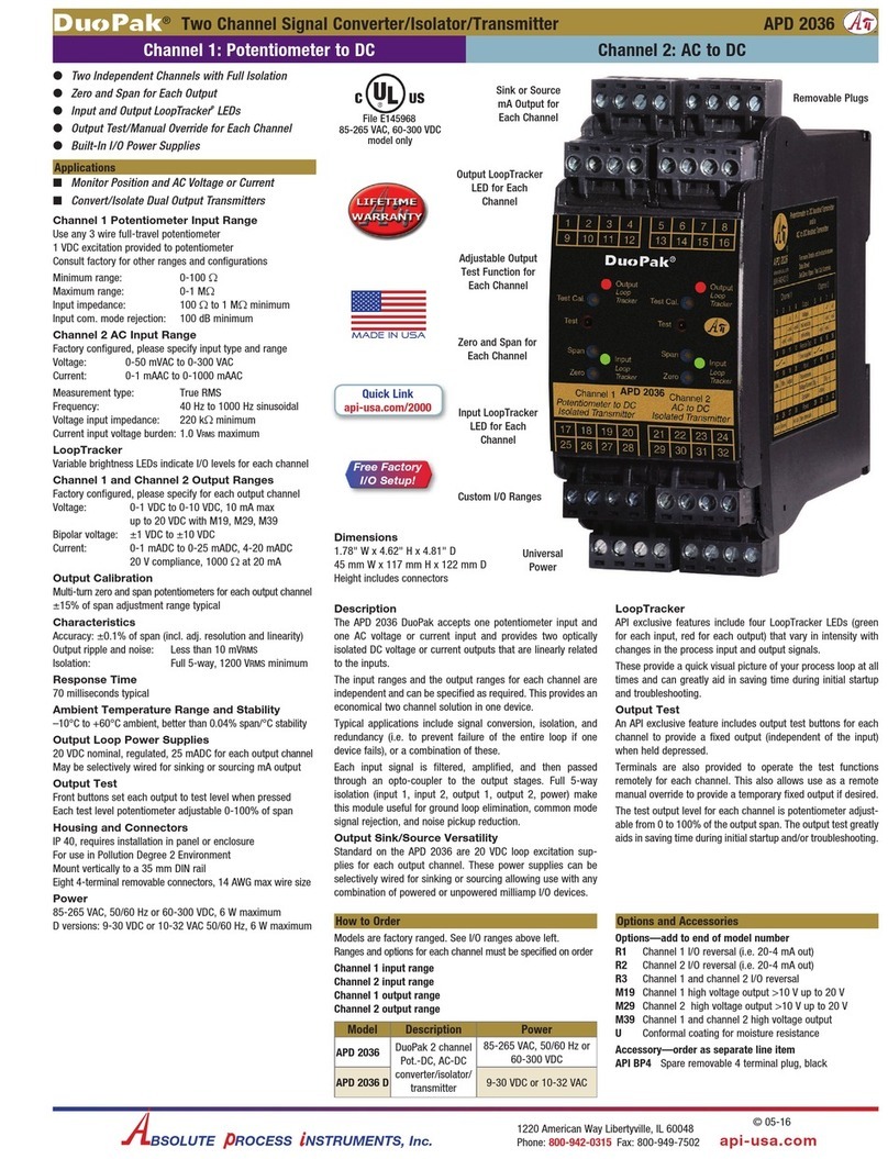
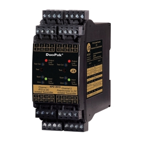
The APD 2017 accepts one RTD or thermistor input and one
frequency input and provides two optically isolated DC voltage or
current outputs that are linearly related to the inputs.
Green LoopTracker®input LEDs provide a visual indication that
each signal is being sensed by the input circuitry of the module.
They also indicates the input signal strength by changing in inten-
sity as the process changes from minimum to maximum.
If an LED fails to illuminate, or fails to change in intensity as the
process changes, check the module power or signal input wiring.
Note that it may be difficult to see the LEDs under bright lighting
conditions.
Two red LoopTracker output LEDs provide a visual indication that
the output signals are functioning. They become brighter as the
input and each corresponding output change from minimum to
maximum.
For a current output the red LED will only light if the output loop
current path is complete. For either current or voltage outputs,
failure to illuminate or a failure to change in intensity as the process
changes may indicate a problem with the module power or signal
output wiring.
Electrical Connections
WARNING! All wiring must be performed by a qualified electrician or
instrumentation engineer. Consult factory for assistance.
Avoid shock hazards! Turn signal input, output, and power off
before connecting or disconnecting wiring.
Polarity must be observed for signal wiring connections. If the input
and/or output do not function, check wiring and polarity.
Each product is factory configured to your exact input and output
ranges as indicated on the white serial number label.
Check label for module operating voltage to make sure it matches
available power. The power supplies are fuse protected and the unit
may be returned to API for fuse replacement.
Outputs
For milliamp ranges determine if your devices provide power to the
current loop or if the loop must be powered by the APD module.
Typical voltage may be 9-24 VDC at your device's terminals if it
provides power to the loop.
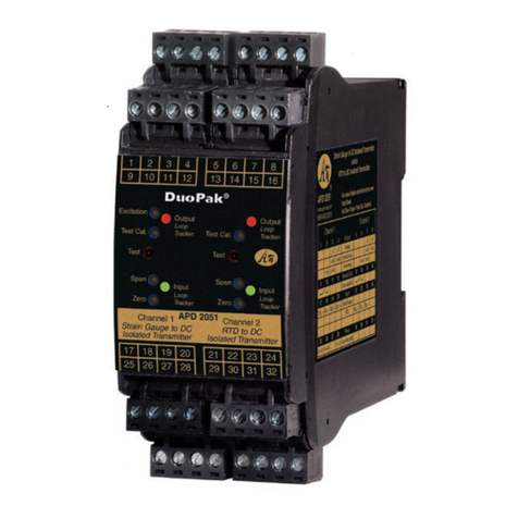
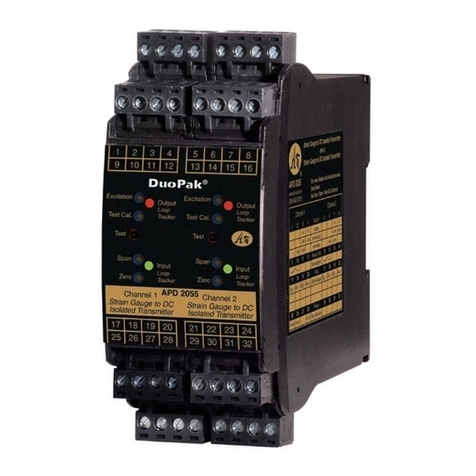
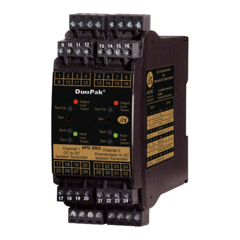
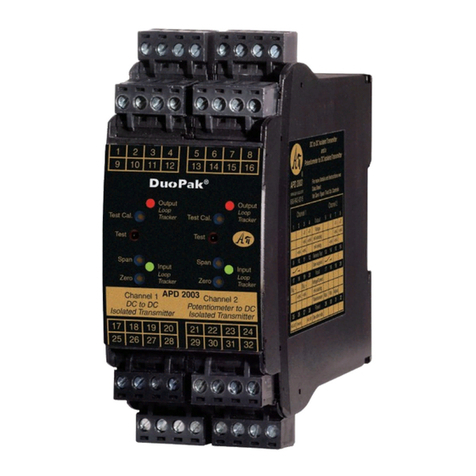
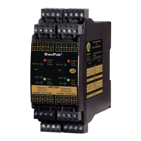
APD 2017
Channel 1 Channel 2
RTD to DC Frequency to DC
Isolated Transmitter Isolated Transmitter
Test Cal.
Span
Zero
Test
Output
Loop
Tracker
Test Cal.
Span
Zero
Test
Output
Input
Loop
Tracker
Loop
Tracker
Input
Loop
Tracker
Channel 1 Channel 2
®
Sensitivity
1413 15 16109 11 12
External
Contacts
for Test
Function
– + 20V – + 20V
mA
Device 2
Ri
mA
Device 1
Ri
65 7 821 3 4
Current
Sourcing
Output
Ch. 1 Ch. 2
Voltage
Output
– +
Voltage
Device 1
– +
Voltage
Device 2
21 3 4
Ch. 1 Ch. 2
65 7 8
– +
mA
Device 2
Ri
Loop
Power
Source 2
– +
+–
mA
Device 1
Ri
Loop
Power
Source 1
Current
Sinking
Output
Ch. 1 Ch. 2
21346578
+–
1817 19 20
Ch. 1
3-Wire Input
1817 19 20
28 Power AC or DC –
26 Earth Ground
25 Power AC or DC +
2625 27 28
To maintain
full isolation
avoid com-
bining power
supplies in
common with
inputs, out-
puts, or unit
power.
2 Wire
2221 23 24
–
+15 VDC
+Sig
2 wire using 15 V supply
See sensor specs. if
bleed resistor is required
15 kΩtyp.
2 Wire
2221 23 24
2 wire self-generating
–+Sig
3 wire NPN
See sensor specs. if load
resistor is required
NPN
2221 23 24
–
+15 VDC
+Sig
Load resis.
3 wire PNP
See sensor specs. if
load resistor is required
2221 23 24
–
+15 VDC
+Sig
PNP
Load resis.
Device for Output Channel 1 Terminal Terminal
Measuring/recording device accepts a
voltage input. 3 (–) 4 (+)
Measuring/recording device has
an unpowered or passive mA input.
APD module provides the loop power.
3 (–) 4 (+20 V)
Measuring/recording device has a mA
input and powers the current loop. 2 (–) 3 (+)
Device for Output Channel 2 Terminal Terminal
Measuring/recording device accepts a
voltage input. 7 (–) 8 (+)
Measuring/recording device has
an unpowered or passive mA input.
APD module provides the loop power.
7 (–) 8 (+20 V)
Measuring/recording device has a mA
input and powers the current loop. 6 (–) 7 (+)
Temperature Input Ch. 1 Term. Term. Term.
Two wire RTD or thermistor 17
Signal –
Jumper
18 & 19
19
Signal +
Three wire RTD 17
Signal –
18
Exc.
19
Signal +
Input 1, Temperature
The sensor type and temperature range are factory configured. See
the model/serial number label for sensor type and range.
Input 2, Frequency
The input range is pre-configured at the factory. No input calibration
is necessary. The frequency input is compatible with most types of
sensors that product a minimum 100 mV amplitude change and a
minimum 5 microsecond pulse width. A 15 VDC supply is available
to power the sensor if required. Always refer to the sensor manu-
facturer's data sheet to determine supply voltage compatibility and
proper wiring.
Sensor Load
The frequency signal input is capacitively coupled to prevent any DC
in the input. Some sensors, typically those without an internal load
resistor, require a resistive load in order to function.
The resistor value may be specified by the sensor manufacturer
as the "minimum resistive load" or calculated from the sensor
manufacturer's specified "load current range".
The 15 VDC power supply is capable of providing 25 mA. A load
current range of 3 mA to 25 mA would typically use a 5 kΩto 500
Ωresistor.
Module Power Terminals
Check white model/serial number label for module operating volt-
age to make sure it matches available power.
When using DC power, either polarity is acceptable, but for
consistency, wire positive (+) to terminal 25 and negative (–) to
terminal 28.
Frequency Sensor Ch. 2 Signal
Com.
Sensor
Power
Signal
Input
2 wire or Namur
requiring external power n/a 22 (+15 V) 23 (+)
2 wire self generating (VR) 21 (–) n/a 23 (+)
3 wire PNP or NPN 21 (–) 22 (+15 V) 23 (+)
API maintains a constant effort to upgrade and improve its prod-
ucts. Specifications are subject to change without notice. Consult
factory for your specific requirements.
Mounting
The housing clips to a standard 35 mm DIN rail. The housing is IP40
rated and should be mounted inside a panel or enclosure.
1. Tilt front of module down and posi-
tion the lower spring clips against the
bottom edge of DIN rail.
2. Push front of module upward until
upper mount snaps into place.
Removal
Avoid shock hazards! Turn signal
input, output, and power off.
1. Push up on bottom back of module.
2. Tilt front of module downward to
release upper mount from top edge
of DIN rail.
3. The module can now be removed
from the DIN rail.
Spring Clips
Upper Mount
