Advanced MxPro 5 User manual


Specifications:
Models, Sales Order Parts:
Mxp-547 Pager Interface Card
Mxp-547-BX Pager Interface (Boxed)
Applications / Limitations:
For use with Pager Systems compliant to ESPA 4.4.4 protocol
If a printer is also required, fit an internal Mxp-512 printer assembly.
Compatibility:
A new PC configuration program (MxPager) is provided for configuring the pager interface.
The interface has been compatibility tested with Multitone pager systems.
The Mxp-547 can be installed on the chassis plate in the medium, large and deep panels.
The Mxp-547-BX can be used with all Mx-5000 Series panels.
Item
Specification Details
Power supply
15-30V DC (e.g. Wired from panel 24V auxiliary supply)
Supply current
50mA (typical at 24V DC).
Temperature
-5°C to 50°C
Humidity
95% Humidity (non condensing)
Dimensions
PCB: 85mm H x 105mm W x 15mm D
Enclosure: 218mm H x 300mm W x 45mm D
Panel Interface
RS232 Galvanically (Opto) isolated
Pager Interface
RS232 Galvanically (Opto) isolated
Fault Input
Non-monitored / Monitored (10K EOL, 470R active)
Maximum № of Pagers
250
Maximum № of Groups
50
Maximum № of Pagers
per Group
8
Event Types Supported
Fire Alarm, Test Alarm, Plant Alarm, Pre-Alarm, Fault, and Disablement
As our policy is one of constant product improvement the right is therefore reserved to modify product specifications without prior notice
www.acornfiresecurity.com
www.acornfiresecurity.com

3
Table of Contents Page
1INSTALLATION..............................................................................................................................................4
1.1 FITTING THE CARD IN A PANEL..................................................................................................................4
1.2 MOUNTING THE BOXED VERSION...............................................................................................................4
1.1 STATUS INDICATIONS................................................................................................................................5
1.1.1 Heartbeat LED Indicator ....................................................................................................................5
1.1.2 RS232 Activity LEDS .........................................................................................................................5
1.2 WIRING TO THE PAGER INTERFACE............................................................................................................5
2CONFIGURATION..........................................................................................................................................6
2.1 GENERAL CONFIGURATION OPTIONS.........................................................................................................7
2.1.1 General Options.................................................................................................................................7
2.1.2 Retransmission ..................................................................................................................................7
2.1.3 Text Cuts............................................................................................................................................8
2.2 PAGER INTERFACE COMMUNICATIONS SETTINGS.......................................................................................9
2.3 PAGER EVENTS........................................................................................................................................9
2.4 PAGER GROUPS.....................................................................................................................................10
2.5 SHIFT TIMES...........................................................................................................................................10
2.6 PAGER ZONES........................................................................................................................................11
2.7 UPLOAD COMMUNICATIONS ....................................................................................................................11
3FAULT CODES.............................................................................................................................................12
www.acornfiresecurity.com
www.acornfiresecurity.com

4
1 Installation
1.1 Fitting the Card in a Panel
Mount the card to the pillars on the chassis plate using the four M3 screws supplied.
Connect 24V DC supply from the AUX output to the connections on the Pager Interface.
OBSERVE POLARITY!
Connect the RS232 serial connection between the base card and the Pager Interface.
Connect: TX –RX,
RX –TX
GND –GND
1.2 Mounting the Boxed Version
The enclosure dimensions and fixing
points are shown in the diagram
opposite.
Connect 24V DC supply from the AUX
output to the connections on the Pager
Interface.
OBSERVE POLARITY!
Connect the RS232 serial connection
between the base card and the Pager
Interface.
Connect: TX –RX,
RX –TX
GND –GND
Run the cabling in rigid conduit or use
fire rated cable. Note: Maximum
distance of 3m (10ft) between the FACP
and the interface.
WARNING: HIGH VOLTAGE INSIDE
DO NOT REMOVE COVER
No Serviceable Parts Inside
Pager Interface
Base Card
RS232 Wiring
DC PWR Wiring
226mm
35mm
17mm
172mm
Cable Anchor
Points x2
Earth Termination
Points x4
Back Box Fixing
Points x4
Pager
Comms
Pager
Fault
Power
IN
Comms
IN
Recommended
Knockout Usage
Pager Interface
www.acornfiresecurity.com
www.acornfiresecurity.com
5
1.1 Status Indications
Status indications are provided on the card to show operation of the interface.
1.1.1 Heartbeat LED Indicator
The Heartbeat LED will normally flash at a rate of 1Hz (once per second) to indicate that the card is
operating.
1.1.2 RS232 Activity LEDS
LED2: RS232 RX –Lit when data is received from the fire panel.
LED1: RS232 TX –Lit when data is transmitted to the fire panel.
LED10: RS232 RX –Lit when data is received from the pager.
LED9: RS232 TX –Lit when data is transmitted to the pager.
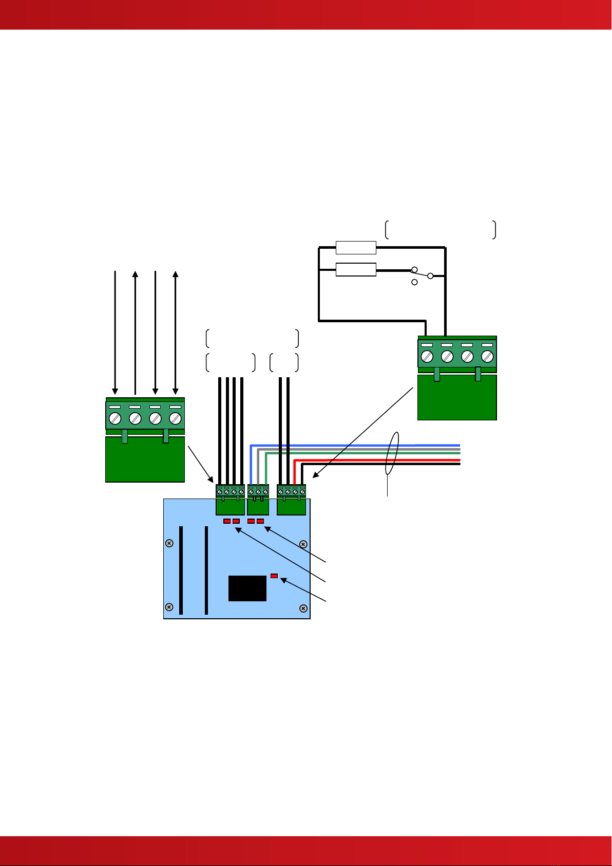
1.2 Wiring to the Pager Interface
The Serial Interface follows the standard RS232 interface connections. Run the cabling in rigid conduit or use
fire rated cable. Note: Maximum distance of 3m (10ft) between the Interface and the Pager.
Connect the TX terminal of the interface to the RX (RXD-Receive) input of the pager.
Connect the RX terminal of the interface to the TX (TXD-Transmit) output of the pager.
Connect the GND terminal of the interface to the 0V or GND terminal of the pager.
Pager Interface
Power and Data to FACP
RS232
I/F
Fau
lt
Interface to the ESPA
Pager System
GND (Ground)
RX (Receive from Pager)
TX (Transmit to Pager)
CTS (Clear to Send from Pager)
+24
V
0V
10K
470R
Fault Input Arrangement
Monitored Input
LED –Heartbeat
LED –RS232 to PAGER
LED –RS232 to FACP
www.acornfiresecurity.com
www.acornfiresecurity.com

6
If required, the CTS terminal of the interface can be connected to the DTR output of the pager if this is provided.
Using the MxPager program, the fault input can be configured as monitored (used) / non-monitored (unused)
and can be inverted to provide compatibility with Normally Open (Inverted) or Normally Closed fault relay output
contacts.
The diagram above shows the EOL arrangement for the monitoring of the relay output contacts. The diagram
shows the normally closed condition.
2 Configuration
The MxPager software is used to configure the operation of the unit.
The program uses the standard RS232 upload / download lead supplied with the PC-NET-003 PC CONFIG
software for connecting the PC to the Pager Interface.
The software is supplied on a CD. To install the software onto the PC, insert the CD and the program should
auto-run. Follow the on-screen prompts to install the software.
If the auto-run feature is disabled or does not run, select START, RUN and enter D:\setup.exe where D: is the
drive letter of your CD drive.
To run the program, select Start, All Programs, Advanced Electronics, MxPager.
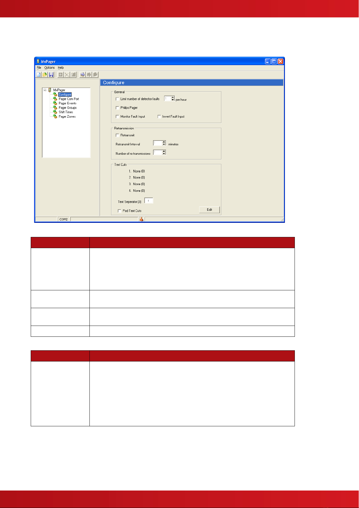
The program will open up with a new (blank) configuration file. The screen is as follows:
Use the normal windows “New, Open and Save” functions to create / open a file via
either the “File” menu or the buttons.
The tree view on the left shows the list of configurable options.
The active view on the right shows the parameters and functions that can be changed for the option selected.
Additional buttons are available and are context sensitive and are
grouped into common functions as follows.
a) Add / Delete / Edit pager addresses
b) Connect to / Disconnect from / Upload to target pager interface.
www.acornfiresecurity.com
www.acornfiresecurity.com
7
2.1 General Configuration Options
The general configuration options provide a set of specific settings to configure the interface to the type of pager
in use and how the pagers are to be notified with information. The default (new) screen is shown below:
2.1.1 General Options
Item
Description
Limit number of
detector faults
This can be used to prevent a large number of faults, say due to a loop
failure, swamping the pager system.
Unticked, the interface will report all faults as they occur.
To restrict the number of possible fault messages, tick the box and then
set the number of fault per hour in the range 1 –250.
Philips pager
Tick this box if the pager is specifically a Philips pager system. Leave
unticked for all other pager systems.
Monitor Fault Input
Tick this box to utilise the fault input circuit. Leave unticked to ignore the
fault input circuit.
Invert Fault Input
Tick this box to Invert the signal and monitor NO relay contacts.
2.1.2 Retransmission
Item
Description
Retransmit
Unticked, the interface will report all events only once as they occur.
Tick the box to retransmit the events more than once.
Set the retransmit interval in the range 1 –30 minutes. Set the number of
retransmissions in the range 1 –255.
NOTE: If the condition persists and if a pager address has been assigned
to the ALL CALL Group, then the interface will send a message to the ALL
CALL pager address after all normal retransmissions have occurred. This
will be sent after the programmed retransmit interval.
www.acornfiresecurity.com
www.acornfiresecurity.com

8
2.1.3 Text Cuts
The information to be sent to the pager can be configured
to specific system information and / or user text.
Some pagers have limited display capability.
To accommodate this restriction, the text can be further
cut to send only part of the available message so that a
composite message can be built up from various sources.
Up to four text cuts can be defined.
Note: Text cuts are from the beginning of the available
string. For example, the zone text can be up to 32
characters in length. Applying a text cut of 6 will mean
that the first six characters of the string are sent to the
pager. (i.e. “Ground Floor West” would be sent as
“Ground”).
Press the EDIT button and a pop-up screen will be shown
as opposite:
Click on one of the available text types and using the
mouse pointer, drag this down to one of the text cut
fields.
Build up the message order and then determine the
length (cut) of each string to be built in to the full
message.
User text can be entered / typed into the boxes to the
right of the item.
For example:
The pager is to be sent a message in the format:
FIRE/FAULT/ALARM –ZONE0001 –ZONE TEXT (16
characters)
The example screen image opposite shows the settings
required.
The maximum length of each item is detailed in the table
below.
Item
Maximum Length
Device Text
26
Zone Text
32
Event Text
16
Point Address
12
Event Time
8
Zone Number
4
User Text
16
NOTE: The Pager interface automatically strips off any
“spaces” after the text characters and only sends the
actual text characters.
For example: The text <LIBRARY ROOM > is sent as <LIBRARY ROOM>
If The PAD TEXT CUTS option is ticked then these trailing “space” characters are included in the message.
www.acornfiresecurity.com
www.acornfiresecurity.com
9
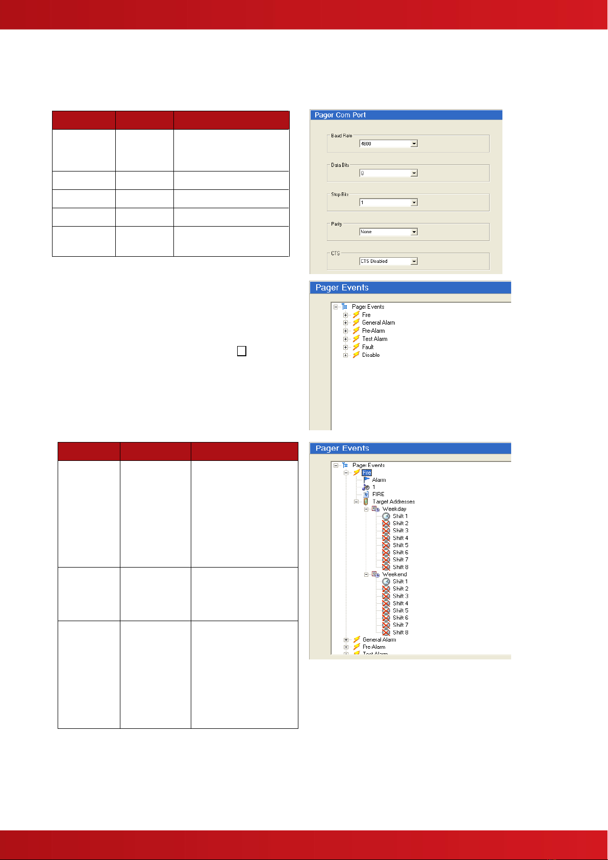
2.2 Pager Interface Communications Settings
The serial interface can be configured to the settings of the pager system. Refer to the pager system
documentation for further details on the settings required.
The table below shows the options available.
Item
Default
Options
Baud Rate
4800
600, 1200, 2400,
4800, 9600, 19200,
38400 and 57600
Data Bits
8
7, 8
Stop Bits
1
1, 2
Parity
None
None, Odd, Even
CTS
Disabled
Disabled, Enabled,
Switched
2.3 Pager Events
In the pager events option, it is possible to determine
to which pagers each type of event should be sent
and to configure some basic event parameters.
The active window shows and event tree with all of
the possible event types.
To configure an event type, click on the + symbol to
expand the tree.
The Basic options are described in the table below.
Right click on the item to edit its setting.
Item
Default
Options
Flag
Fire = Alarm
Alarm, Plant
Alarm, Pre-
Alarm and
Fault = High
Disable and
Enable =
Normal
Alarm
High
Normal
Beep
Code
1
0 –9 Refer to the
pager documentation
to see if it supports
this option.
Text
Fire
Alarm
Plant Alarm
Pre-Alarm
Fault
Disable
Enable
Up to 16 characters
–this text is used in
the “Event Text”
string –see the
section on Text Cuts.
There can be up to 8 shifts per day for
both weekdays and for weekend days.
Shifts that are not configured are crossed
out.
www.acornfiresecurity.com
www.acornfiresecurity.com

10
Right Click on a shift to add a pager –a text entry box is
displayed. Enter the address of the pager to which these
messages should be sent either directly in the box or select from a
drop down list by clicking the down arrow button.
The list presented includes all defined individual
pagers and pager groups currently unused
in this shift.
For confirmation, the zone ranges assigned to the pager (if defined)
are shown alongside the pager number. For example, Pager 12
opposite is assigned to Zones 1-25 and 110-233.
Pager Addresses can be up to four (4) digits in length and can consist
of the numbers 0-9, the characters A-F or a wild card (*)
character. For example, these could be –1, 09, A1, B1F, 9010 or A1*D
(i.e. A10D to A1FD).
NOTE: Addresses “1”, “01”, “001” and “0001” are not the same pager.
A combination of up to three (3) individual addresses or groups can be assigned to a shift.
2.4 Pager Groups
To simplify event programming, pagers can be
assigned to pager groups. A group can consist
of up to eight (8) individual pager addresses.
Select the group required and Right Click to
“Add” a pager address. A text entry box is
displayed. Either enter the number of the pager
to which these messages should be sent
directly in the box or select from a drop down list
by clicking the down arrow button.
The list presented
includes all defined
individual pagers
currently unused in
this group.
2.5 Shift Times Up to eight shifts can be
defined for weekdays and for
weekend days. As default, each
day is defined as one shift.
Right Click on the blue bar and click
“Add” to add a shift.
Click on the boundary between the
two shifts and drag the
boundary to the required time.
Shifts can be defined in five-
minute intervals.
Repeat the process to define the number of shifts and the shift
times required for both weekdays and weekend days.
www.acornfiresecurity.com
www.acornfiresecurity.com

11
2.6 Pager Zones
Each Pager Address must be configured to define
from which zones the events will be sent to the pager.
This can be used to prevent unnecessary or unwanted
events being sent to all pagers or it can be used to define
only those zones that are relevant to a specific person.
For example, a nurse pager can be configured to cover
only those zones concerned with the hospital wards
covered by the nurse.
Up to two ranges can be defined.
Right Click in the table or on a specific address to Add /
Delete / Edit and entry.
A new pop-up dialogue box is shown.
Define the new pager number and address ranges as
required. See example below.
If only one address
range is required,
then use “Zonal Range 1” only.
The maximum zone range is 1 –2000.
2.7 Upload Communications
To upload the configuration data to the pager interface, first unplug the
cable from the base card and plug in the upload / download lead as
shown opposite.
Click on the “Connect to Target” button and when
communications is established, click on the “Upload” button to transfer the
data.
On completion, remove the upload / download lead and re-fit the lead
from the base card.
Pager Interface
www.acornfiresecurity.com
www.acornfiresecurity.com

12
3 Fault Codes
The following table lists the possible fault conditions reported on the Panel LCD and their meaning. The list is in
descending order of priority.
Item
Description
DEVICE MISSING
The pager interface is not responding to the panel communications.
Check power and serial communications connections to the interface.
Check that the Heartbeat LED on the interface is flashing.
CORRUPT DATA
The communications between the panel and the pager is being affected.
Check the serial communications connections to the interface.
PROGRAM FAIL
The pager interface has detected a checksum error in its operating
program.
Re-flash the operating program into the interface using the MxFlasher
Tool.
CONFIG. FAIL
The pager interface has detected a checksum error in its configuration
data.
Power down the interface then reapply power. Re-configure the interface
using the MxPager Tool with the configuration settings.
NOT READY
The pager interface has either never been configured or is not fully
configured.
This could occur if the RS-232 lead is disconnected during a
configuration upload.
Re-configure the interface using the MxPager Tool with the configuration
settings.
CPU RESET
The pager interface has just powered up or has been reset due to a
watchdog timer. This will not normally appear on the display but may
appear in the log.
DEVICE FAULT
The pager interface cannot establish communications with the ESPA
Paging system.
Check the serial communications connections between the interface and
the ESPA Pager system.
OPEN CIRCUIT
There is an open circuit condition on the Fault Input wiring.
Check the connections between the interface and the ESPA Pager
system including the EOL resistor.
SHORT CIRCUIT
There is a short circuit condition on the Fault Input wiring.
Check the connections between the interface and the ESPA Pager
system including the EOL resistor.
INPUT FAULT
The Fault Input is in its active condition indicating a fault condition from
the ESPA Pager system.
Check the ESPA Pager system.
NOTE: The input can be configured with an “Invert” property. Check that
the correct configuration has been used for this input’s required
operating properties.
Normal
The interface and the Fault Input are in their normal operating condition.
NOTE: Transmission to the Pager Interface is prevented whilst the panel is in COMMISSION mode. This is to
prevent the paging of unwanted / spurious messages whilst commissioning / testing the panel.
www.acornfiresecurity.com
www.acornfiresecurity.com


Other manuals for MxPro 5
2
This manual suits for next models
2
Table of contents
Other Advanced Recording Equipment manuals


