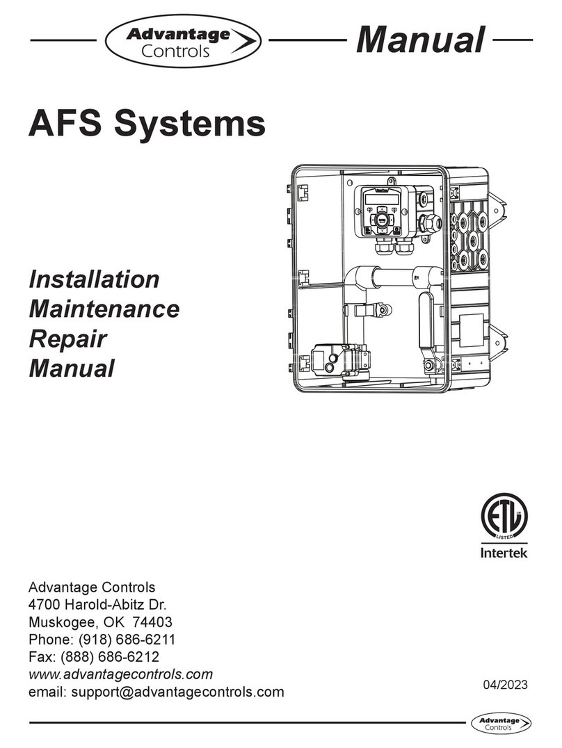
Advantage Controls SFS Series Operating instructions

1
Manual
SFS Series
Solid Feed Systems
Installation
Maintenance
Repair
Manual
Advantage Controls
4700 Harold Abitz Dr.
Muskogee, OK 74403
Phone: 918-686-6211
Fax: 888-686-6212
www.advantagecontrols.com

2
SFS Series Manual
Table of Contents
Contents Page
I. Introduction ................................................................................3
Model Numbering.......................................................................3
Options.......................................................................................4
II. Installation..................................................................................5
Electric Models .................................................................5
Non-Electric Models..........................................................6
III. Operation ...................................................................................6
IV. Option C-2 Operation.................................................................7
A. Front Panel Display ..........................................................7
a. System Menu Functions .............................................7
b. Control Panel LED Lights ...........................................7
c. Control Panel Buttons.................................................7
B. Controller Set-Up ..............................................................7
C. System Operation .............................................................7
D. Resetting Bowls ................................................................8
E. C-2 Menu Display Options................................................8
V. Diagrams....................................................................................9
A. SFS-101............................................................................9
B. SFS-G01.........................................................................10
C. SFS-G02......................................................................... 11
D. SFS-105..........................................................................12
VI. Trouble Shooting Guide ...........................................................13
VII. Warranty and Factory Service Policies ....................................14

3
I. Introduction
The SFS system is engineered to inject city water into a bowl containing a solid chemical which will then be
dissolved and drained into a chemical solution tank based on high/low level switches. All systems primarily
consists of:
1. Liquid Level controller (except SFS-G01, SFS-G02, SFS-10 and SFS-20 models).
2. A Universal dissolving bowl.
3. ¼”plumbingmanifoldwithshut-o,solenoidvalve,pressureregulatorandpressuregauge.
4. Molded solution tank with pump mounting shelf.
5. Atwoleveloatswitchassembly(exceptSFS-G01,SFS-10andSFS-20models).
Note: Inlet water pressure needs to be at 45-50 psi for best disolution.
Model Numbering
SFS systems have two base controller models, a full featured 120 VAC controller or the mini 12 VDC control-
ler. Your unit may be supplied with one or more of the features described in this manual. To determine what
features apply to your unit, check the model number label located on the controller.
SFS-G01 - Single dissolving bowl in a tank with non-electric make-up valve.
SFS-G02 - Dual dissolving bowls in a tank with non-electric make-up valve
SFS-101 - Provides a mini 12 VDC controller, dissolving bowl and a supply water plumbing assembly mount-
ed on a molded solution tank.
SFS-201 - Provides two SFS-101 units mounted on a poly panel with one water inlet.
SFS-105 - Provides a 120 VAC Liquid Level Controller with one solution tank, liquid level controller, universal
dissolving bowl and a supply water plumbing assembly mounted on a poly panel.
SFS-205 - Provides a 120 VAC Liquid Level Controller, two universal dissolving bowls and a supply water
plumbingassembly,solenoidvalveandvegallonsolutiontankmountedonapolypanel.
SFS-305 - Provides a 120 VAC Liquid Level Controller, three universal dissolving bowls and a supply water
plumbingassembly,solenoidvalveandvegallonsolutiontankmountedonapolypanel.
SFS-10 - Dissolving bowl with 120 volt solenoid, pressure regulator, no tank or controller.
SFS-20 - Two dissolving bowls with one 120 volt solenoid, regulator, no tank or controller.

4
Options
AConduit connections
A2 240 volt with conduit connections
B1 Back check in pump suction line
D1” FNPT port on the top of the tank for conductivity probe (not needed with C2)
D2 Adjustable level wand for external monitoring
E 10’of3/4”I.D.cleartubingforoverow
GBlue back panel for 105 and 205
H Highlevelalarmwithrelayoutputandcut-o
H2 Highlevelcut-oforSFS-101withDCcontroller
H3 Highalarmwithcut-oandsecondbrasssolenoidN.O.on120voltunits
H4 Highlevelcut-osonSFS-201,120voltmodualandN.O.brassshut-ovalves
KGray dissolving tank
LProvide 120 volt level controller for remote mounting with SFS-101
PNon Advantage Controls metering pump mounting adapter
R1 Remove pressure regulator from 205, 305 & 405 (R2, R3 to remove more than one)
T2 Dual timer on SFS-205 instead of level controller (Includes MicroTron Timer manual)
WAdjustable wands

5
II. Installation
Non-Electric Model Installation
Step 1
• Remove the two screws on top
plate of solid feeder (Fig. A).
• Liftocoverandsetonit’sside.
Step 2
• Clipweightedoattobottomof
wire hanger via cutout (Fig. B).
Step 3
• Insertweightedoatbackinto
solid feeder (Fig. C).
Note:Makesureweightedoat
is centered on wire hanger and
that the hanger moves freely up
and down through cap.
Step 4
• Reattach the two screws
previously removed in Step 1.
WARNING:Transportingthefeederwiththeweightedoatattachedtothe
hangercandamagethehangerandcausethevalvetonotshut-ocorrectly.
Figure A
Figure B
Figure C

6
Electric Models
The standard units are designed to be free standing or wall mounted. The level controller, control solenoid
valveandleveloatassemblyareallprewiredforeasyinstallation.
Models with 120 VAC controllers are supplied with an 8 foot, 3-wire grounded power cord.
Models with 12 VDC controllers are supplied with a wall plug-in transformer.
A ¼” MNPT connection is supplied for the incoming water supply. The pressure of the incoming water should
not exceed 110 PSI.
The reservoir tank has a molded pump mounting shelf. Various pump mounting accessories will be included
dependinguponthemodelnumberforsecuringpumptotank.Aoodedsuctionconnectionisalsoprovided
for the chemical feed pump.
Notes: 1. Pressure regulators are preset to approximately 40 psi. If incoming water pressure is below 50
psi the regulator will need to be set to a lower level to insure proper valve operation. Turning the
small knob on regulator counter clockwise will reduce the incoming line pressure.
2.Allmodelshaveanairgapdesignutilizingtheoverowport(seepage8)thatprovidesa
positivebackowpreventionleavingnopressurizedpathfordissolvedsolutionbackintothe
fresh water supply line.
III. Operation
The electric level controller will activate a relay to power the make-up water solenoid when the solution level
inthereservoirtankbecomeslowandturnsotherelaywhenthesolutiontankbecomesfull,reachingthe
secondoator(high)point.Thestandardleveloatpositioningand1”MNPTconnectionforoverowto
be piped to drain are designed to maintain a maximum solution level of 2.5 gallons. Changing the pressure
regulator setting will change the dissolving rate.
An additional high-level override switch input can be added with the H option on models that operate on
120VAC.Ifthecontrollerdetectsacontactfromthehighalarmswitch,thecontrolrelayisturnedoand
the alarm relay is activated. Models operating on 12 VDC have the H2 option in which the high alarm simply
turnsothecontrolrelay.
Muti-bowl models are designed to eliminate valuable maintenance time and create easy upkeep.
Option C-2 will allow a feed system to operate 2 or more bowls sequentially switching automatically by using
a conductivity controller, increasing the jug replacement interval.

7
IV. Option C-2 Operation
A. Front Panel Display
a. System Menu Functions:
Calibrate - Conductivity of dissolved liquids.
Switch At - Conductivity value in which the system will advance to the next bowl.
Sprayingon#1-Identiesthebowlinuse.
ZeroCond-Identiesthezeroconductivityvalue.
b. Run Mode Explanation:
Power- Illuminates when the controller is supplied with 120/240VAC.
Relay - Illuminates when a relay is activated.
Alarm-Illuminateswhenthenalbowlhasbeenutilized.
c. Control Panel Buttons:
View- displays menu options screen and returns back to run mode.
Function Select- advances menu options.
Value Adjust- changes menu settings.
Test- activates relays and alarms on for 3 minutes.
B. Controller Set-up
1. Press VIEW then adjust the FUNCTION SELECT knob to view functions.
2. Stop on the desired function and use the VALUE ADJUST knob to change the value.
3. After setting a value, adjust FUNCTION SELECT knob again to advance to the next function.
4. Press VIEW after setting the controller to continue with the run mode.
Note: PresstheTESTbuttontoforceallrelayson,pressagaintoforceo,pressagaintoreturnto
normaloperation.Ifforcedonoro,theunitwillreturntonormalafter3minutes.
C. System Operation
In order to activate the conductivity on the controller both level wands must be down (closed) to start,
with the 1st relay on for spraying on bowl 1. Both level wands must be up (open) to stop, to turn the
“FILL”relayso.
1.Uponstartup,theconductivityofthesolutioninthetankhasnoeectonthecontroller.Thetank
mustbelledandemptiedonetimebeforethecontrollerwillconsidertheconductivity.Thissimply
means,thelevelwandsmustbothgouptostartllingthetankandthentheymustbothgodownto
show an empty tank. At this point the controller will accept the conductivity reading.
2. When the conductivity drops below the “Switch At” point, the system will switch from Bowl #1 (Relay
#1)toBowl#2(Relay#2),Bowl#1willhaveutilizedthesolidchemicalbythispoint.Thersttime
the controller switches to Bowl #2, it will not consider the conductivity; once again, until the tank has
beenlledandemptiedonetime.
3. The controller will continue operating on Bowl #2, even if the conductivity drops below the “Switch
At” point while utilizing Bowl #2 the ALARM led will activate. If the controller has option “H”, then a
relay will also activate for the alarm. This relay can be 120/240VAC or a dry contact.

8
D. Resetting Bowls
WhenAUTORESETisenabled,thiswillallowthecontrollertoautomaticallyresetitselftotherst
bowl after the last bowl has gone “low conductivity”. Set to Y will enable.
When disabled (Set to N), the controller will function as below:
When the controller is utilizing Bowl #2, it must be manually switched back to Bowl #1, presummably
after the solid chemical jugs have been changed. This can be done by:
1. Pressing the “VIEW” button and then rotating the “FUNCTION SELECT” knob two clicks clockwise.
The display will read “RESET TO BOWL #1”.
2. By rotating the “VALUE ADJUST” knob (either direction). The display will change to “SPRAYING
ON #1”. Chemical Bowl #1 will be used to start the new run cycle.
3. You may then press the “VIEW” button so the controller will return to the “run” mode.
(The controller will return to “run” mode after 3 minutes.)
E. C-2 Menu Display Options
Press
VIEW BUTTON
to view menu
options
Press
VIEW BUTTON
to return to
run mode
Turn VALUE
ADJUST to change setting
Turn FUNCTION
SELECT to change menu
CALIBRATION
Turn VALUE
ADJUST to change setting
Turn FUNCTION
SELECT to change menu
SWITCH AT
Turn VALUE
ADJUST to change setting
Turn FUNCTION
SELECT to change menu
SPRAYING ON #1
Turn VALUE
ADJUST to change setting
Turn FUNCTION
SELECT to change menu
ZERO COND
Turn VALUE
ADJUST to change setting
Turn FUNCTION
SELECT to change menu
AUTO RESET? Y

9
V. Diagrams
A. SFS-101
SFS-101 Parts List
1
6
2
3
4
57
8
9
10
11
13
12
1. SFS-DB-1
2. SFS-TANK-101
3. 2C4A000056
4. SFS-SUCTION
5. SFS-SB-12V
6. R00223
7. SFS-BV
8. SFS-PR
9. SFS-PG
10. SFS-C01
11. SFS-LF-2
12. 2C4A000059
13. SFS-DB-ARM-1
SFS-PA-101M includes #5, 7, 8, 9 & polyboard
Dissolving bowl (includes spray arm)
Replacement Tank
1” MNPT to 3/4” tubing barb overflow elbow
Outlet pump suction assembly
Brass solenoid valve with y-strainer 12 volt D.C.
SS wall mounting bracket
Brass inlet valve
Pressure regulator
Pressure gauge
12 vold controller
2 level float assembly
Replacement spray nozzle
Spray arm (includes spray nozzle)

10
B. SFS-G01
SFS-G01 Parts List
1
10
2
3
8
12
11
1. SFS-DB-1
2. SFS-TANK-G01
3. SFS-SUCTION
4. 2C4A000056
5. SFS-BV
6. SFS-Y
7. SFS-PR
8. SFS-PG
9. SFS-LF-G01
9a. SFS-FV-G01
10. R00223
11. 2C4A000059
12. SFS-DB-ARM-1
13. SFS-FLOAT
SFS-PA-G01 includes #5, 6, 7, & 8
Dissolving bowl (includes spray arm)
Replacement Tank
Outlet pump suction assembly
1” MNPT to 3/4” tubing barb overflow elbow
Brass inlet valve
Y-strainer
Pressure regulator
Pressure gauge
Level float & inlet valve assembly (includes weight & polyboard)
Fill valve assembly only - no float
SS wall mounting bracket
Replacement spray nozzle
Spray arm (includes spray nozzle)
Float bottle
4
5
7
9
6
9
13
9a

11
C. SFS-G02
1
5
8
7
6
4
3
SFS-G02 Parts List
1. SFS-BV
2. SFS-TANK-G02
3. SFS-DB-1
4. 2C4A000056
5. SFS-SUCTION
6. SFS-LF-G02
7. SFS-PR
8. SFS-Y
9. SFS-PG
10. 2C4A000059
11. R00339
Brass inlet valve
Tank
Dissolving bowl
1” MNPT to 3/4” tubing barb overflow elbow
Outlet pump suction assembly
Level float & inlet valve assembly (includes weight & polyboard)
Pressure regulator
Y-strainer
Pressure gauge
Replacement spray nozzle (not shown)
SS wall mounting bracket (not shown)
9
2

12
D. SFS-105
SFS-105 Parts List
1. SFS-DB-1
2. SFS-TANK-101
3. 2C4A000056
4. SFS-SUCTION
5. SFS-SB-120V
6. R00223
7. SFS-BV
8. SFS-PR
9. SFS-PG
10. SFS-C105
11. SFS-LF-2
12. 2C4A000059
13. SFS-DB-ARM-1
SFS-PA-101M includes #5, 7, 8, 9 & polyboard
Dissolving bowl (includes spray arm)
Replacement Tank
1” MNPT to 3/4” tubing barb overflow elbow
Outlet pump suction assembly (left or right)
Brass solenoid valve with y-strainer 120 volt A.C.
SS wall mounting bracket (not shown)
Brass inlet valve
Pressure regulator
Pressure gauge
Level controller
2 level float assembly
Replacement spray nozzle (not shown)
Spray arm (includes spray nozzle)
1
2
3
4
11
13
5 7
9
10
8

13
VI. Trouble Shooting
PROBLEM CAUSE REMEDY
Solenoids not
activating
Power Source
Output Power
Bad or Dirty Level Floats
Faulty Wiring to Level Floats
Check power source
Check or replace fuse
Clean or replace as needed
Leveloatsasneeded
System not spraying Dirty Bowl Injection Nozzle
Clogged Y-Strainer Screen
Low Water Pressure
Clean as needed
Clean as needed
Lower regulator setting
No system power Power Source
Check Fuse
Check power source
Replace as needed
No output power Check Ribbon (120/240V Controller)
Check Fuse
Make sure connection is fully seated on
both ends
Replace as needed
(C-2 Option)
False reading Bad or Dirty Electrode
Out of Calibration
Clean as needed
Calibrate unit
Will not calibrate Dirty Electrode
Faulty Electrode
Faulty Wiring to Electrode
Out of Calibration
Clean electrode
Replace controller or
Replace as needed
Calibrate unit
Alarm Lights ON System has utilized all bowls Reset to bowl #1

14
VII. Manufacturer’s Product Warranty
Advantage Controls warrants control systems of its manufacture to be free of defects in material or workman-
ship. Liability under this policy extends for 24 months from date of installation (sensors are not included).
Liability is limited to repair or replacement of any failed equipment or part proven defective in material or
workmanship upon manufacturer’s examination. Removal and installation costs are not included under this
warranty. Manufacturer’s liability shall never exceed the selling price of equipment or part in question. Ad-
vantage disclaims all liability for damage caused by its products by improper installation, maintenance, use
or attempts to operate products beyond their intended functionality, intentionally or otherwise, or any unau-
thorized repair. Advantage is not responsible for damages, injuries or expense incurred through the use of
its products. The above warranty is in lieu of other warranties, either expressed or implied. No agent of ours
is authorized to provide any warranty other than the above.
30 Day Billing Memo Policy
Advantage Controls maintains a unique factory exchange program to ensure uninterrupted service with
minimum downtime. If your controller malfunctions, call 1-918-686-6211 (international customers dial +1918
686-6211), and provide our technician with Model and Serial Number information. If they are unable to di-
agnose and solve your problem over the phone, a fully warranted replacement unit will be shipped, usually
within 48 hours, on a 30 Day Billing Memo. This service requires a purchase order and the replacement unit
is billed to your regular account for payment. The replacement unit will be billed at current list price for that
model less any applicable resale discount. Upon return of your old unit, credit will be issued to your account
if the unit is in warranty. If the unit is out of warranty or the damage not covered, a partial credit will be applied
based upon a prorated replacement price schedule dependent on the age of the unit. Any exchange covers
only the controller or pump. Electrodes and other external accessories are not included.

15
- Notes -

16
Get the Advantage in Water Treatment Equipment
Advantage Controls can give you the Advantage in products, knowledge
and support on all of your water treatment equipment needs.
Cooling Tower Controllers
Boiler Blow Down Controllers
Blow Down Valve Packages
Solenoid Valves
Water Meters
Chemical Metering Pumps
Corrosion Coupon Racks
Chemical Solution Tanks
Solid Feed Systems
Feed Timers
Filter Equipment
Glycol Feed Systems
Pre Fabricated Systems
Get the Advantage
5
4
3
2
1
0
9
8
7
6
BACK
HOME
HELP
ENTER
CANCEL
SET UP
RUN
5
4
3
2
1
ENTER
HELP
5
4
3
CHANGE
RUN
SET UP
0
9
8
2
1
7
6
HOME
BACK
This manual suits for next models
9
Table of contents
Other Advantage Controls Water System manuals
Popular Water System manuals by other brands
Solarbayer
Solarbayer FRIWA 65 Kaskade KL2 Product information

Jung Pumpen
Jung Pumpen compli 300 instruction manual
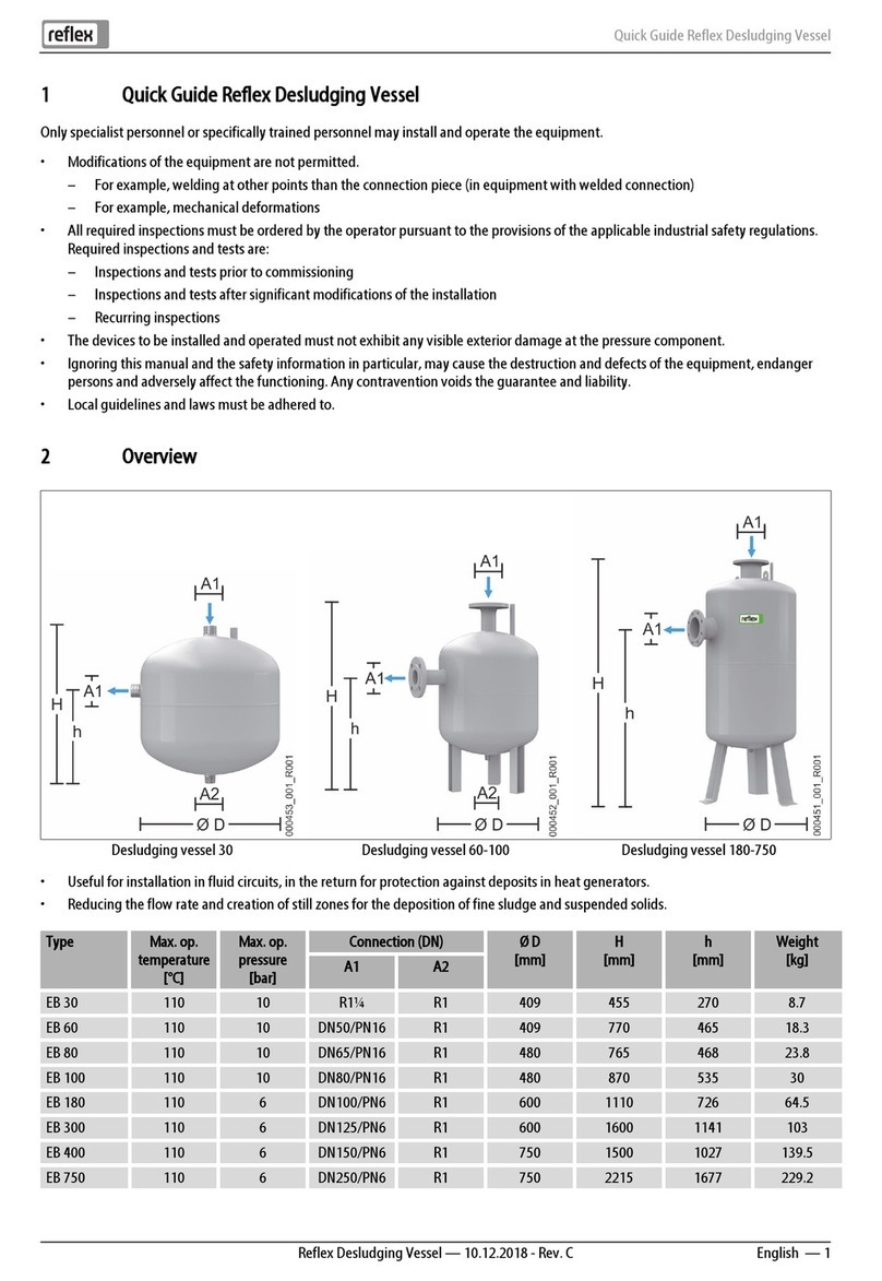
Reflex
Reflex EB 30 quick guide
Watts Premier
Watts Premier 5 SV DELUXE Installation, operation and maintenance manual
Infiltrator
Infiltrator H-20 installation instructions

Reverse Osmosis
Reverse Osmosis Economy RO75 owner's manual
