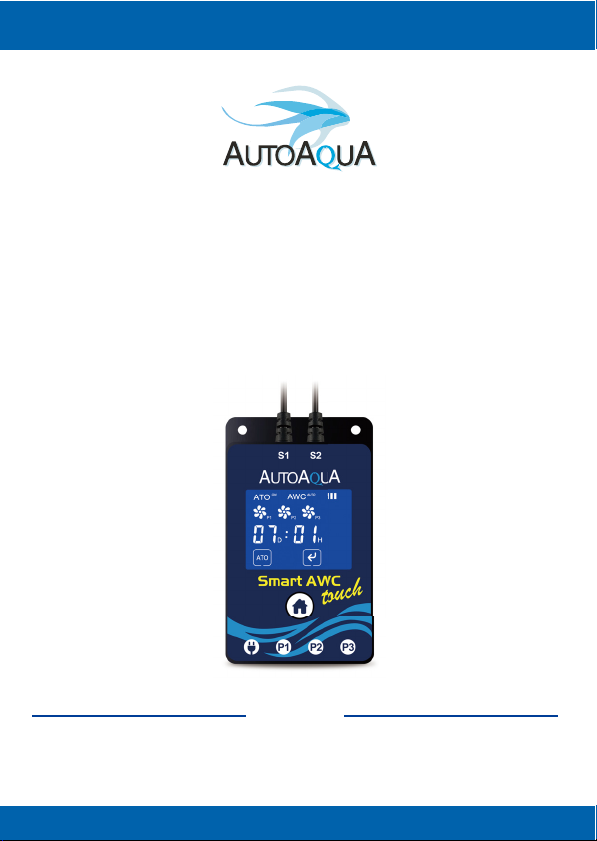
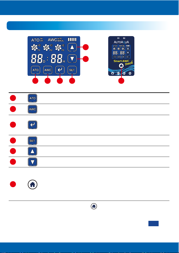
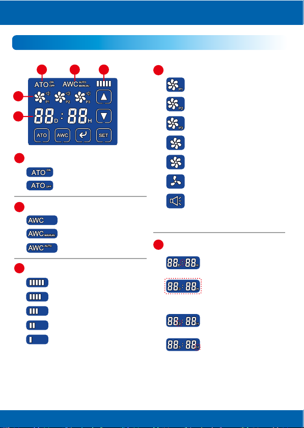
AutoAqua Smart AWC touch SAWC-200P User manual

Model
SAWC-200P
Manual
Bedienungsanleitung
Mode d’emploi
Smart AWC touch
Change for Simple

English
01
Item Pictures Description
Smart AWC touch
Controller X 1
1. Controller with touch panel &
Optical Level Sensor with wet
side magnet X 2
: Black sensor
:Blue sensor
2. Dry side magnet X 2
3. Max tank thickness : 1/2” (12.7mm)
1. Rell pump for ATO
2. Drain pump for AWC
3. Rell pump for AWC
1. Mount for the water tube
2. For use on rimed and rimless tanks
3. Max tank thickness : 1/2” (12.7mm)
Universal Power Supply
A connector to break the siphon
Used with DC pumps
Power Adapter X 1
DC Pump X 3
Universal Tube Holder X 3
Siphon Breaker X 3
Water Tube 6M X 1
List of Parts

English
02
Installation
1. AWC (Automatic Water Change)
Smart AWC touch Controller
Tank/Sump
Changed Water Volume
Step 1 :
Mount black sensor
() to normal water
level - ATO water level.
Step 2 :
Mount blue sensor ( )
to low water level.
: ATO/AWC Sensor (Rell)
: AWC Sensor (Drain)
: Power DC Jack
: ATO Rell Pump DC Jack
: AWC Drain Pump DC Jack
: AWC Rell Pump DC Jack

English
03
Tank/Sump
Waste Water Container
AWC Drain Pump
Waste Water
Step 3 :
Connect AWC drain tube
(pump siphon breaker*
tubing holder).
Step 4 :
Connect AWC
drain pump’s
cable to P2.
Arrow on siphon
breaker indicates
water flow direction.
*Note : Place siphon breaker inside the tank/sump but
above the water level.
Air In : Siphon breaker allows air in to break the siphon
when the pump turns off.
Water Out : Water drops out of the hole are normal when
the pump is on.
Air In
Water Out

English
04
2. ATO (Auto Top O)
New Water ReservoirTank
/S
um
p
Waste Water
C
ontainer
AWC Refill Pump
Power
W
as
t
e
W
a
t
e
r
Step 7 :
Connect AWC
controller’s power.
Step 6 :
Connect AWC rell pump’s
cable to P3.
Step 5 :
Connect AWC
rell tube.
Tank/Sump
Step 1 :
Mount black sensor ( )
to normal water level.

English
05
ATO ReservoirTank/Sump
ATO Refill Pump
Step 3 :
Connect ATO rell
pump’s cable to P1.
Step 2 :
Connect ATO rell
tube (pump siphon
breaker* tubing
holder).
*Note : Place siphon breaker inside the tank/sump but
above the water level.
Air In : Siphon breaker allows air in to break the siphon
when the pump turns off.
Water Out : Water drops out of the hole are normal when
the pump is on.
Air In
Water Out
Arrow on siphon
breaker indicates
water flow direction.

English
06
AT
O
ReservoirTank
/S
um
p
AT
O
Re
f
ill Pum
p
Step 4 :
Connect AWC
controller’s power.
Power

English
07
The volume can be calculated by multiplying the width and length of your
tank and the distance between the pyramids of the two sensors. *
For example, a tank has 18 inches in length and 17 inches in width. If the
distance between the two sensors is 3 inches, the water volume to be
changed will be around 4 gallons.
18”(L) X 17” (W) X 3”(H) = 918 cubic inches (around 4 gallons)
* The water volume might be inuenced by factors such as the speed of return pump.
Slower relling speed could reduce the variation. Please refer to the 3rd part of
Programming section.
Calculating Water Volume to Be Changed
Length : 18”
Width : 17”
Changed Water Volume Height : 3”
1. Old water in the tank/sump is pumped out until the water
level reaches S2.
2. There is a 3-minute pause before relling new water.*
3. New water is relled into the tank/sump until the water level
reaches S1.
*Users can skip the pause in AWC MANUAL mode by touching .
Auto Water Change Process

English
08
No. Icon/Button Function
1
1
2
2
3
3
4
4
5
5
6
6
7
7
Icons & Buttons for Setting
OFF
OFF
OFF
Turn ATO on or o
Choose AWC mode : MANUAL / AUTO or turn AWC o
Choose the setting item in the AWC MANUAL / AUTO mode
Increase time / speed
Decrease time / speed
1. Wake up the LCD display
2. Dismiss alarm
3. Return to AWC setting page*
4. Resume the process
5. Reset (hold at least for 8 seconds)
*During water change process, pressing button will stop the process and
return to the previous AWC MANUAL / AUTO setting status. Also, ATO will be
forced to be turned o if its previous status is on and at the same time the
controller will give a ve-second audible and visual alert (ATO ashing ).
1. Start the AWC process
2. Pause / resume the AWC process
3. Dismiss alarm

English
09
1
1
2
2
3
34
4
5
5
Display Indication
Status of ATO
Status of AWC
Speed (For AWC Rell Pump) *
*For further details, please refer to
the 3rd part of Programming section.
*For further details please refer to
page 11.
: ATO is on.
Status of Pump
Status of Timer (For AWC AUTO Mode)
: ATO rell pump is connected.
: AWC drain pump is connected.
: AWC rell pump is connected.
showing : The pump is o.
rotating : The pump is on.
ashing : The pump is paused.
ashing : QST alarm*
Timer’s colon ashing :
The timer is running.
Timer’s D ashing :
DAY is being set.
Timer’s H ashing :
HOUR is being set.
Timer’s numbers, D and H
ashing : The timer is
paused.
: ATO is o.
: Speed 5
: Speed 4
: Speed 3
: Speed 2
: Speed 1
: AWC is o.
: AWC is in AUTO mode.
: AWC is in MANUAL mode.

English
10
Alarm and Reminder
Connect the pump cable.

English
11
Smart AWC touch uses QST for real-time protection against any failure situation.*
The controller will give an audible and visual alert when any one of the following
situations occurs.
For ATO: Any relling time is 3 times longer than the rst relling time.
For example, if the rst relling time is 10 sec, the controller will give an alert
when any relling time is over 30 sec.
For AWC: Any draining time or relling time is 3 times longer than the rst one.
For example, if the rst draining or relling time is 20 sec, the controller will give
an alert when any draining or relling time is over 60 sec.
*1. No security time control for the rst relling and draining.
2. The minimum security time for ATO relling is 10 sec, while the minimum security time for
AWC draining or relling is 20 sec.
Reset : Holding for at least 8 sec is the only way
to clear the QST memory (the rst draining time and
the rst relling time).
After reset, please unplug and replug the power cable.
Quick Security Technology (QST)
How to Reset?

English
12
1. AWC MANUAL Mode (One-time AWC)
In this mode, users have to manually start the AWC process.
1) Touch to choose AWC MANUAL mode.
2) Touch to set the relling speed if needed.
* Please refer to Refilling Speed Setting.
3) Touch to start water change process.*
*When water change is done, ashes for 3 minutes with 5 beeps at last.
* Since the timer is not running during a power outage, the next water change process will be delayed.
For example, if a water change process is set to be started at 3 p.m., however, a power outage occurs
during the countdown and lasts for one hour, the next water change process will be started at 4 p.m.
1. ATO will be turned o automatically (ATO ashing ) after restoration of
power as if its previous status is on. It will be turned back on after 15 minutes
automatically. Users could also turn it back on manually.
2. When the power outage occurs during the draining or relling process, the
process will be delayed for 15 minutes after restoration of power and then resume.
3. When the power outage occurs during the countdown to water change (the
timer will pause during power outage)*, the timer will retain the record and
resume after power outage.
Power Outage Security Measures
Programming
OFF
OFF
OFF

English
13
2. AWC AUTO Mode (Periodic AWC)
Water change in AUTO mode will perform in two dierent ways when ATO is o
and on.
When ATO is o, it performs periodic AWC. Users set the timer to decide the water
change interval.* The minimum water change interval is one hour while the
maximum one is 99 days and 23 hours. Water change process will be started after
the completion of each countdown.
When ATO is on, AWC does not perform in xed intervals. Users set up timer to
decide how many times AWC is expected to perform in a period. For example, if
users would like to do water change 24 times per day, the timer is set for one hour.
Water change process will be started after the next ATO event. Also, water change
process will be done as many times in a row as it is delayed. For example, if you
have set AWC every 1 hour and the ATO tops up every 3 hours, then after 3 hours
the ATO will top up and directly afterwards the AWC will perform 3 AWC cycles.
1) Touch to choose AWC AUTO mode.
2) Touch to set the relling speed if needed.
*Please refer to Refilling Speed Setting.
3) Touch again to enter DAY SETTING of timer.
4) Touch again to enter HOUR SETTING of timer.
5) Touch to start water change cycles.*
*1. It is recommended to do water change in MANUAL mode to estimate the duration of water change
process before doing water change in AUTO mode.
2. The water change interval must be longer than the duration of water change process. If the duration of
water change process is longer than the water change interval, it will trigger 0000 or 1111 alarm, and
the next countdown will not be started. It is recommended for users to extend the interval or shorten the
duration of water change process.
3. When water change is done, ashes for 3 minutes.

English
14
3. AWC Refilling Speed Setting
The relling speed will select dierent lengths of relling time. The slower the speed is,
the longer the relling process is.
For example, one relling process takes 25 sec. At Speed 3, the pump will rell 10 sec
and pause 200 sec repeatedly until the completion of the relling.
Speed 5 no pause during the relling process
Speed 4 rell 20 sec and pause 200 sec repeatedly
Speed 3 rell 10 sec and pause 200 sec repeatedly
Speed 2 rell 5 sec and pause 200 sec repeatedly
Speed 1 rell 2 sec and pause 200 sec repeatedly
Low Average Speed
Start Finish
Rell
10 sec Pause
200 sec Rell
10 sec Pause
200 sec Rell
5 sec
1. Power Input : 100-240VAC 50-60HZ
2. DC Pump :
● Head : 6.5 ft (200 cm)
● Flow Rate : 74 gph (280 Iph)
3. Max Tank Thickness : 1/2” (12.7mm)
Optical Level Sensor
Front View Side View
0.53“
(13.4mm)
0.25“
(6.4mm)
Magnet
0.5”
(12.7mm)
0.78“
(20mm)
Specications
Slower relling of AWC water helps minimize temperature and
chemistry changes so as to reduce stress on aquarium
inhabitants. Also, it reduces the variation in water volume to be
changed.
Benefits of AWC Refilling Speed Setting

English
15
Warranty Period
One year from the purchase date
Purchase Date
Warranty Card
Place of Purchase Service
(Store name, phone, email, address)
(Y/M/D)
1. Any incorrect operation will not be warranted and will result in a repair fee.
2. All warranty repairs are performed by the worldwide distributor.
3. This guarantee is eective on the date listed on your sales receipt.
AUTOAQUA Technologies Co., Ltd.
7F-7.,NO.229,Fuxing 2nd Rd.,Zhubei
City, Hsinchu County,Taiwan
E-mail : [email protected]
www.autoaqua.com.tw
* Please go to AUTOAQUA website to
get the distributor information.
1. Please read the manual in detail before installation.
2. If using another ATO and not the AWC ATO, please shut o your ATO before
doing an AWC.
3. Avoid setting up controller in an area with micro bubbles.
4. When power outage occurs during the process of top-o or water change,
the process will continue within 15 minutes after restoration of power.
Notice

Deutsch
16
Artikel Bild Beschreibung
Smart AWC touch
Controller X 1
1. Controller mit Touch Panel &
Optischer Füllstandsensor mit
eintauchbarem Magnet für
Innenscheibe X 2
: Schwarzer Sensor
:Blauer Sensor
2. Magnet für Außenscheibe X 2
3. Max. Glasdicke : 12,7mm
1. Nachfüllpumpe für ATO
2. Ablaufpumpe für AWC
3. Nachfüllpumpe für AWC
1. Schlauchbefestigung
2. Für Aquarien mit und ohne
Verstärkungen
3. Max. Glasdicke : 12,7mm
Universal-Stromversorgung
Steckverbinder für Rückschlagventil
Verwendung mit den
DC Pumpen
Netzteil X 1
DC Pumpen X 3
Universal-Schlauchhalter X 3
Rückschlagventil X 3
Wasserschlauch 6M X 1
Teilen Liste
1
2
3

Deutsch
17
Einrichtung
1. AWC (Automatischer Wasserwechsel)
Smart AWC touch Controller
Aquarium/Technikbecken
Menge des
Wasserwechsels
Schritt 1 :
Montieren Sie den
schwarzen Sensor ( )
an der Stelle des
normalen Wasserstands
- ATO Wasserstand.
Schritt 2 :
Montieren Sie den
blauen Sensor ( ) an
der Stelle des niedrigen
Wasserstands.
: ATO/AWC Sensor (Nachfüllen)
: AWC Sensor (Ablauf)
: Stromanschluss
: Anschluss ATO Nachfüllpumpe
: Anschluss AWC Ablaufpumpe
: Anschluss AWC Nachfüllpumpe

Deutsch
18
Aquarium/Technikbecken
Abwasserbehälter
AWC Ablaufpumpe
Abwasser
Schritt 4 :
Schließen Sie
das Kabel der
AWC
Ablaufpumpe
an P2.
Der Pfeil auf dem
Rückschlagventil
zeigt die Wasserflies-
richtung an.
*Hinweis : Das Rückschlagventil muss höher sein als der
Wasserstand im Aquarium oder Behälter.
Lufteingang : Das Rückschlagventil ermöglicht ein
Luftansaugen, wenn die Pumpe ausgeschaltet wird.
Wasserausgang : Es ist normal das Wassertropfen aus
dem Rückschlagventil kommen, wenn die Pumpe
eingeschaltet ist.
Lufteingang
Wasserausgang
Schritt 3 :
Schließen Sie den AWC
Ablaufschlauch an.
(Pumpe Rückschlagventil *
Schlauchhalter)

Deutsch
19
2. ATO (Automatische Wasserzufuhr)
NachfüllwasserbehälterAquarium
/
Technikbecke
n
A
b
w
asse
r
be
h
ä
lt
e
r
AWC-
Nachfüllpumpe
Strom
A
b
w
asse
r
Schritt 7 :
Schließen Sie die
Stromversorgung des
AWC-Controllers an.
Schritt 6 :
Schließen Sie das Kabel der
AWC-Nachfüllpumpe an P3.
Schritt 5 :
Schließen Sie
den AWC-Nach-
füllschlauch an.
Aquarium/Technikbecken
Schritt 1 :
Montieren Sie den
schwarzen Sensor ( ) an
der Stelle des normalen
Wasserstands.
Other manuals for Smart AWC touch SAWC-200P
2
This manual suits for next models
2
Table of contents
Languages:
Other AutoAqua Water System manuals
Popular Water System manuals by other brands

Barnstead
Barnstead D14031 Operation manual

Kenmore
Kenmore 625.381560 owner's manual

Whirlpool
Whirlpool WHES48 Installation & operation manual

Grunbeck
Grunbeck safeliQ:EB Operation manual

Clever
Clever PURE instruction manual

SMITH & LOVELESS
SMITH & LOVELESS SONIC START STREAMLINE H87A457 Installation & operation instructions