2
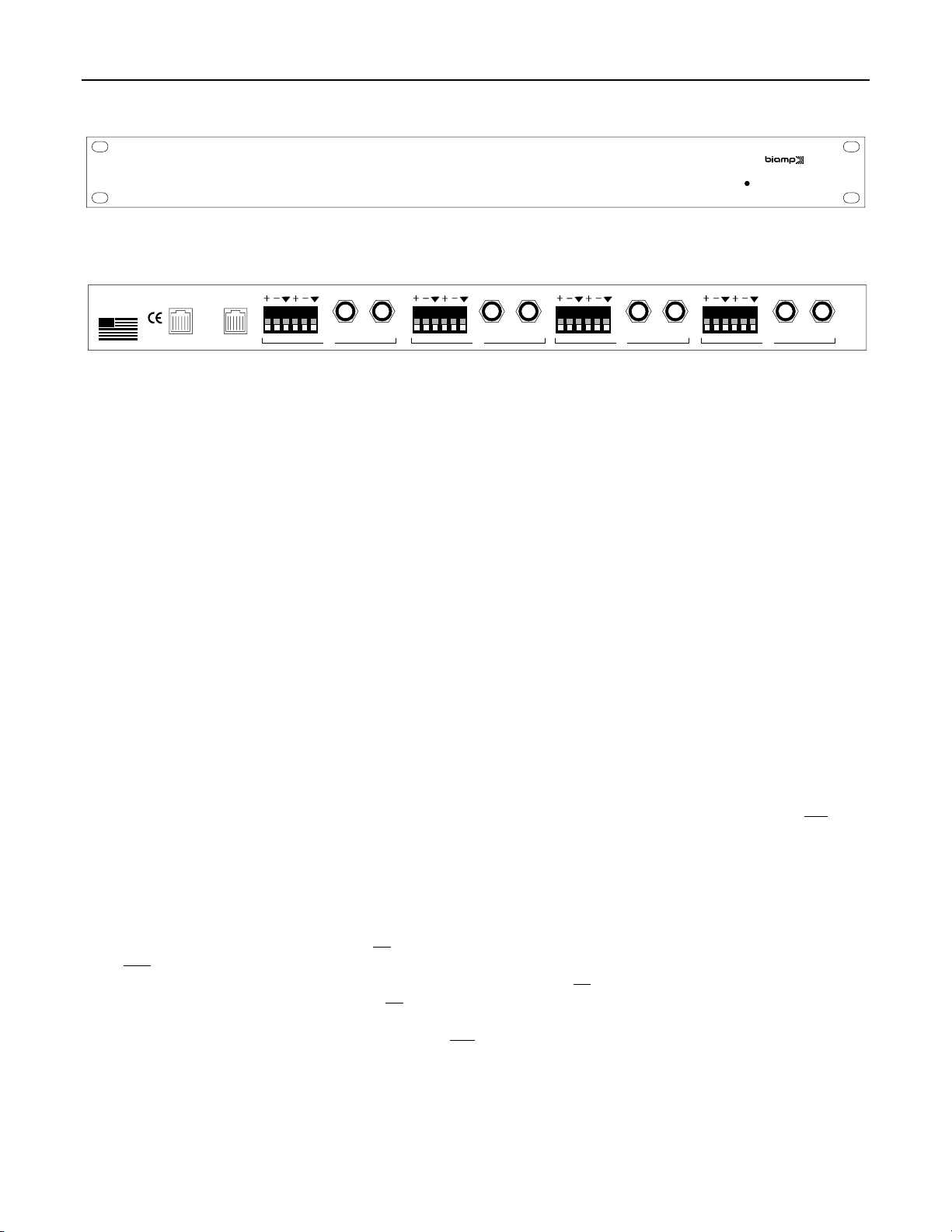
FRONT & REAR PANELS
on
Device Matching Driver
ADVANTAGE DMD
(1)
±12VDC 15W
Class 2
wiring
MADE IN U.S.A.
BIAMP SYSTEMS
Portland, Oregon
an affiliate of
Rauland-Borg Corp.
patch in/out patch in/out patch in/out patch in/outpatch in/out
in
4
DC outDC out DC in
out in
out in
out
in
out
3 2 1
(2) (3) (4) (5) (6) (7)
(1) On Indicator: This red LED indicates power is applied to the module (see DC In below).
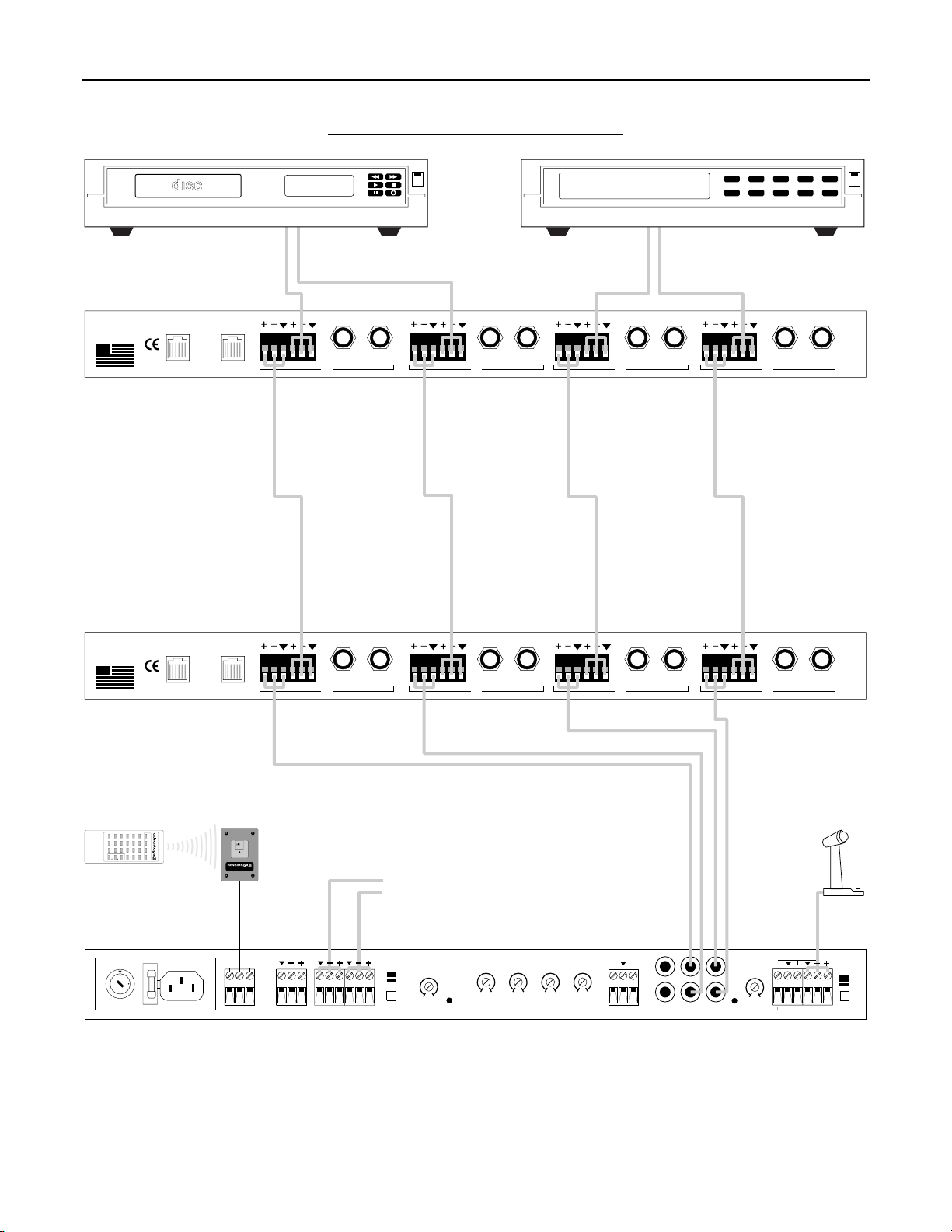
(2) DC Out: This Modular jack supplies ±12 Volts DC power for additional DMD (or System One) modules. When powering multiple
modules from a single power source, connect DC Out of the first module to DC In of the second module, and so forth (see DC In below).
(3) DC In: This Modular jack accepts ±12 Volts DC power from other Advantage products, or from an optional 12V power supply. An
Advantage DMD typically requires 75 mA of current. When powering multiple modules from a single power source, check the current
capability of the power source. If the combined current requirement of the multiple modules exceeds the current capability of the power
source, then additional power supplies may be needed. The optional 12V power supply has a typical current capability of 165 mA.
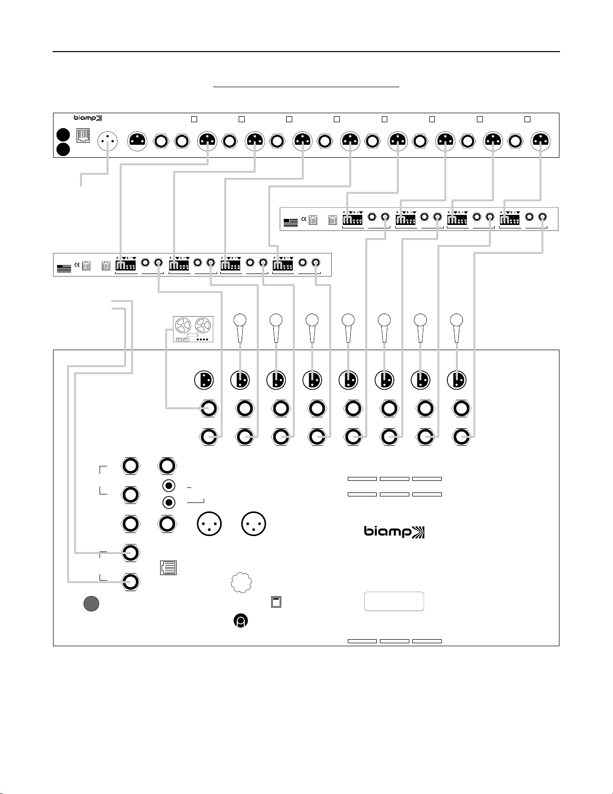
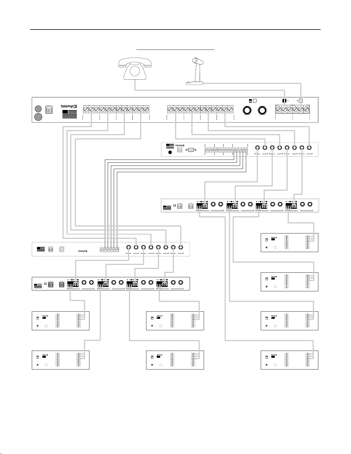
(4) Out: These three screw terminals provide an electronically balanced, cross-coupled output from the channel. The screw terminals are
provided on a plug-in barrier strip, which allows pre-wiring of cables before installation. For balanced connections, wire high to (+), low to
(-), and ground to (
ý
). For unbalanced connections, wire high to (+) and ground to both (-) & (
ý
). From the factory, these outputs provide
line-level signals. However, internal jumpers allow each output to be independently attenuated (-60dB) for microphone-level applications
(see Jumper Options on page 3). Internal jumpers also allow Channel 1 input signal to be assigned to Channel 2 Out, and Channel 1~3
input signals to be individually assigned to Channel 4 Out (see Jumper Options on page 3). Channel 2 Out & Channel 4 Out provide a
combination of all input signals which have been assigned to them, while Channels 1 & 3 maintain their individual output capabilities.
(5) In: These three screw terminals provide an electronically balanced, differential input to the channel. The screw terminals are provided
on a plug-in barrier strip, which allows pre-wiring of cables before installation. For balanced connections, wire high to (+), low to (-), and
ground to (
ý
). For unbalanced connections, wire high to (+) and ground to both (-) & (
ý
). These inputs accept line-level signals only. Input
signals from Channels 1~3 may be assigned to appear at Channel 4 Out (see Jumper Options on page 3).
(6) Patch: These 3-conductor TRS 1/4" Phone jacks are for connection of the channel input signals to other Advantage products (or
signal processors). Patch jacks are unbalanced, and are wired with Tip being Send, Ring being Return, and Sleeve being Ground. When
connecting Patch jacks to In/Out jacks of other System One products, use 3-conductor TRS 1/4" Phone cables (available from Biamp).
Connection to a Patch jack may also be made using a special 'Y' cable. Patch jacks are independent from the channel Out terminals, so
any signal processing inserted into Patch jacks will not affect the Out signals. Instead, Patch jacks simply provide an additional insert point
for the input signal path. A Patch jack may also be used (with a standard 2-conductor TS 1/4" Phone cable) as an independent output from
the channel.
NOTE: Channel 1 input signal which is assigned to Channel 2 Out will not appear at Channel 2 Patch. Likewise, Channel
1~3 signals which are assigned to Channel 4 Out will not appear at Channel 4 Patch
.
(7) In/Out: These 3-conductor TRS 1/4" Phone jacks provide both input and output of the channels for connection to other Advantage
products (or other mixers). In/Out jacks are unbalanced, and are wired with Tip being Input, Ring being Output, and Sleeve being Ground.
When connecting In/Out jacks to Patch jacks of other System One products, use 3-conductor TRS 1/4" Phone cables (available from
Biamp). This same connection may be made to any mixer having Patch jacks identical to System One products. Connection to a In/Out
jack may also be made using a special 'Y' cable. If only 2-conductor TS 1/4" Phone cables are available, an In/Out jack may be used as
the input, while the associated Patch jack is used as the output.