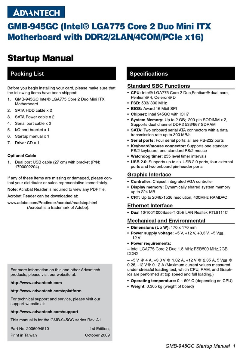
vii ACP-2000MB User Manual
Contents
Chapter 1 General Information ............................1
1.1 Introduction ............................................................................................... 2
1.2 Specifications ............................................................................................ 2
1.3 Power Supply ............................................................................................ 3
Table 1.1: Power supply options ................................................. 3
1.4 Environmental Specifications .................................................................... 3
Table 1.2: Environmental specifications...................................... 3
1.5 Dimension Diagram................................................................................... 4
Figure 1.1 Dimension diagram..................................................... 4
Chapter 2 System Setup.......................................5
2.1 Removing the Top Cover .......................................................................... 6
2.2 Installing the Motherboard......................................................................... 6
2.3 Installing Add-on Cards............................................................................. 7
Figure 2.1 Card cage with riser card............................................ 7
Figure 2.2 Installing PCI add-on card .......................................... 7
2.4 Installing Disk Drives................................................................................. 8
Figure 2.3 Drive bay for 5.25" device and 3.5" FDD.................... 8
Figure 2.4 Drive bay for internal 3.5" HDD .................................. 8
Figure 2.5 Location of storage devices........................................ 9
Chapter 3 Operation............................................11
3.1 The Front Panel ...................................................................................... 12
3.1.1 Switch, Button and I/O Interfaces ............................................... 12
3.1.2 LED Indicators for System Status ............................................... 12
Table 3.1: LED indications function ........................................... 12
3.2 The Rear Panel ....................................................................................... 13
3.3 Replacing the Cooling Fans .................................................................... 13
Figure 3.1 Dual cooling fans...................................................... 13
Figure 3.2 Cooling fan maintenance.......................................... 13
3.4 Replacing the Filter ................................................................................. 14
Figure 3.3 Replacing fan filter and door filter............................. 14
Chapter 4 Alarm Board .......................................15
4.1 Alarm Board Layout ................................................................................ 16
Figure 4.1 Alarm board layout ................................................... 16
4.2 Alarm Board Specifications ..................................................................... 17
4.2.1 Connectors & Pin Definition ........................................................ 17
Table 4.1: CN1, Auxiliary external power connector, standard mini
4-Pin power connector.............................................. 17
Table 4.2: CN4, Thermal sensor (LM75) connector .................. 17
Table 4.3: CN13, Voltage detect. input connector..................... 17
Table 4.4: CN16, Power good input connector.......................... 17
Table 4.5: CN17, Alarm reset connector ................................... 17
Table 4.6: CN18, Output connector to LED board..................... 18
Table 4.7: CN26, HDD LED connector...................................... 18
Table 4.8: FAN1~FAN7, Fan connectors .................................. 18
Table 4.9: J1, External buzzer................................................... 18
Table 4.10:SW1, Fan number select switch............................... 18
