manuals.online logo
Brands
  1. Home
  2. •
  3. Brands
  4. •
  5. Advantech
  6. •
  7. Motherboard
  8. •
  9. Advantech AIMB-764 Installation and operation manual

Advantech AIMB-764 Installation and operation manual

Other Advantech Motherboard manuals

Advantech AIMB-585 User manual

Advantech

Advantech AIMB-585 User manual

Advantech AIMB-740 Series User manual

Advantech

Advantech AIMB-740 Series User manual

Advantech AIMB-641 User manual

Advantech

Advantech AIMB-641 User manual

Advantech SOM-DB4400 User manual

Advantech

Advantech SOM-DB4400 User manual

Advantech PCA-6155V User manual

Advantech

Advantech PCA-6155V User manual

Advantech AIMB-227 AMD Installation and operation manual

Advantech

Advantech AIMB-227 AMD Installation and operation manual

Advantech PCM-9590 User manual

Advantech

Advantech PCM-9590 User manual

Advantech B+B SmartWorx Airborne WLNN-EK-DP551 User manual

Advantech

Advantech B+B SmartWorx Airborne WLNN-EK-DP551 User manual

Advantech PCM-9588 Installation and operation manual

Advantech

Advantech PCM-9588 Installation and operation manual

Advantech ASMB-805 Series User manual

Advantech

Advantech ASMB-805 Series User manual

Advantech PCA-6168 User manual

Advantech

Advantech PCA-6168 User manual

Advantech AIMB-210 User manual

Advantech

Advantech AIMB-210 User manual

Advantech PCM-4824 User manual

Advantech

Advantech PCM-4824 User manual

Advantech PCM-3375 User manual

Advantech

Advantech PCM-3375 User manual

Advantech AIMB-213 User manual

Advantech

Advantech AIMB-213 User manual

Advantech AIMB-740-6CB1 User manual

Advantech

Advantech AIMB-740-6CB1 User manual

Advantech MIO-2261 Installation and operation manual

Advantech

Advantech MIO-2261 Installation and operation manual

Advantech AIMB-554 User manual

Advantech

Advantech AIMB-554 User manual

Advantech SOM-DB2500 User manual

Advantech

Advantech SOM-DB2500 User manual

Advantech PPC-MB-8260 Installation and operation manual

Advantech

Advantech PPC-MB-8260 Installation and operation manual

Advantech AIMB-253 Series User manual

Advantech

Advantech AIMB-253 Series User manual

Advantech AIMB-256 User manual

Advantech

Advantech AIMB-256 User manual

Advantech MIC-3396 User manual

Advantech

Advantech MIC-3396 User manual

Advantech AIMB-785 User manual

Advantech

Advantech AIMB-785 User manual

Popular Motherboard manuals by other brands

Gigabyte MNJ190I-FH user manual

Gigabyte

Gigabyte MNJ190I-FH user manual

Biostar HI-FI-Z87X-3D Setup manual

Biostar

Biostar HI-FI-Z87X-3D Setup manual

Atmel SAM9753PIA-DK user guide

Atmel

Atmel SAM9753PIA-DK user guide

Coapt GEN2 Handbook

Coapt

Coapt GEN2 Handbook

Supero SUPER P4DL6 user manual

Supero

Supero SUPER P4DL6 user manual

Cypress CY3210-PSoCEVAL1 quick start guide

Cypress

Cypress CY3210-PSoCEVAL1 quick start guide

ASROCK B660M-HDV manual

ASROCK

ASROCK B660M-HDV manual

Fujitsu D2831 Short description

Fujitsu

Fujitsu D2831 Short description

Industrial Computers ADE-6050 user manual

Industrial Computers

Industrial Computers ADE-6050 user manual

Asus TUF Z270 MARK 2 manual

Asus

Asus TUF Z270 MARK 2 manual

DFI NB71-BC user manual

DFI

DFI NB71-BC user manual

ASROCK H61 Pro BTC user manual

ASROCK

ASROCK H61 Pro BTC user manual

Norco POS-7893 user manual

Norco

Norco POS-7893 user manual

Intel DG965MS specification

Intel

Intel DG965MS specification

Asus B85M-VIEW PAKER user manual

Asus

Asus B85M-VIEW PAKER user manual

Asus P5G41T-M LX V2 user manual

Asus

Asus P5G41T-M LX V2 user manual

Gigabyte GA-K8VT800-RH user manual

Gigabyte

Gigabyte GA-K8VT800-RH user manual

Gigabyte Z790M AORUS ELITE user manual

Gigabyte

Gigabyte Z790M AORUS ELITE user manual

manuals.online logo
manuals.online logoBrands
  • About & Mission
  • Contact us
  • Privacy Policy
  • Terms and Conditions

Copyright 2025 Manuals.Online. All Rights Reserved.

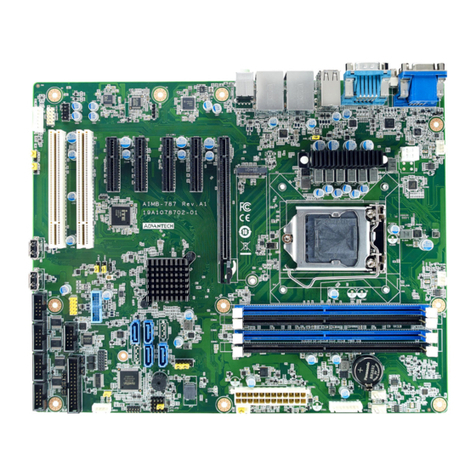
1 AIMB-764 Startup Manual
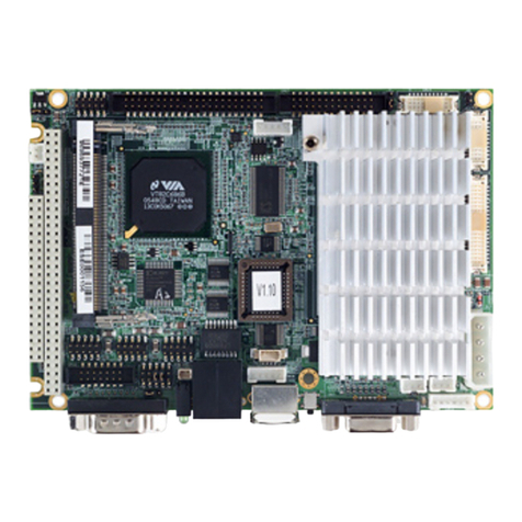
AIMB-764 Socket LGA 775 Intel
®
Core
TM
2 Duo/
Pentium D/ Pentium 4/ Celeron D FSB 1066 MHz
Processor-based ATX Motherboard with PCIe,
DDR2, and Dual GbE
®
TM
Startup Manual
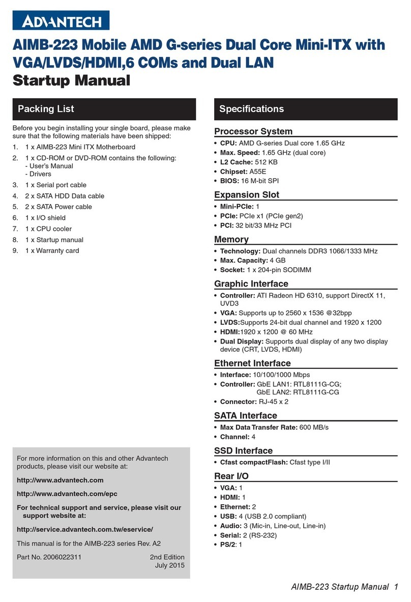
Before you begin installing your card, please make sure
that the following materials have been shipped.
If any of these items are missing or damaged, contact your
distributor or sales representative immediately.
Note: Acrobat Reader is required to view any PDF file.
Acrobat Reader can be downloaded at:
www.adobe.com/Prodindex/acrobat/read-
step.html (Acrobat is a trademark of Adobe).
Standard SBC Functions
• CPU: LGA775 Intel®CoreTM 2 Duo/ Pentium®4/ Pen-
tium®D/ Celeron D
• BIOS: Award 16 Mb SPI BIOS
• FSB: 533/ 800/ 1066 MHz
• Chipset: Intel Q965 with ICH8DO
• System memory: Up to 8 GB four 240-pin DIMM sock-
ets. Supports dual channel DDR2 533/667/800 SDRAM.
Note: Due to the inherent limitations of PC architecture,
the system may not fully detect 8 GB RAM when
8 GB RAM is installed.
• SATA2 Interface: Five on-board serial ATA2 connectors
with a data transmission rate of up to 300 MB/s support-
ing Advanced Host Controller Interface (AHCI) technol-
ogy.
• IDE Interface: Supports PIO mode 4 (16.67 MB/s data
transfer rate) and ATA 33/66/100 (33/66/100 MB/s data
transfer rate) BIOS enabled/disabled.
• FDD interface: Supports one FDD
• Serial ports: Two serial ports, COM1 is RS-232; COM2
is RS-232/422/485
• Parallel port: One parallel port, supports SPP/EPP/ECP
mode
• Keyboard/mouse connector: Supports standard PS/2
keyboard and mouse
• Watchdog timer: 255 level timer intervals
• USB 2.0: Supports up to ten USB 2.0 ports
VGA Interface
• Chipset: Chipset integrated VGA controller
• Display Memory: Dynamically shared system memory
up to 256 MB
• Resolution: Up to 2048 x 1536 @ 75 Hz refresh rate
Ethernet interface
• Interface (Bold): 10/100/1000Base-T
• Controller: LAN1: Intel 82566DM; LAN2: Intel 82573L
Mechanical and Environmental
• Dimensions (L x W): 304.8 x 228.6 mm
• Power supply voltage: +3.3 V, +5 V, ±12 V
• Power requirements: Maximum: +5 V at 3.10 A, +3.3 V
at 1.54 A, +12 V at 9.90 A (Intel Pentium D 3.2 GHz (800
MHz FSB), 4 x 1 GB DDR2 667 SDRAM)
• Operating temperature: 0 ~ 55° C (depending on CPU)
• Weight: 0.5 kg (weight of board)
Packing List Specifications
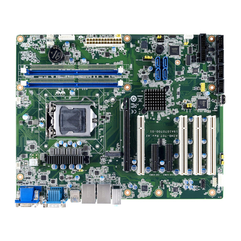
• AIMB-764 Socket LGA 775 Intel®CoreTM 2 Duo/
Pentium D/ Pentium 4/ Celeron D FSB 1066 MHz
Processor-based ATX Motherboard with PCIe,
DDR2, and Dual GbE
• 1 AIMB-764 Startup Manual p/n: 2002076410
• 1 CD with driver Utility p/n: 2066000E10
• 1 FDD cable p/n: 1700340640
• 1 Ultra ATA 66/100 HDD cable p/n: 1701400452
• 2 Serial ATA HDD data cables p/n: 1700003194
• 2 Serial ATA HDD power cables p/n: 1703150102
• 1 COM port cable kit p/n: 1701090401
• 1 I/O port bracket p/n: 1962015680
• 1 jumper package p/n: 9689000068
• 1 warranty card p/n: 2190000902
For more information on this and other Advantech
products, please visit our website at:
http://www.advantech.com
http://www.advantech.com/eplatform
For technical support and service, please visit our
support website at:
http://www.advantech.com/support
This manual is for the AIMB-764 Series Rev. A1.
Part No. 2002076410
1st Edition
October 2007
AIMB-764 Socket LGA 775 Intel
®
CoreTM 2Duo
/
Pentium D
/
Pentium 4
/
Celeron D FSB
1066 MHz Processor-based ATX Motherboard with PCIe, DDR2, and Dual GbE
2 AIMB-764 Startup Manual
The board has a number of jumpers that allow you to con-
figure your system to suit your application. The table
below lists the function of each of the jumpers and con-
nectors.
IRQ11 1-2 Closed
System Reset 2-3 closed
AT Mode 1-2 closed
ATX Mode 2-3 closed
Jumpers and Connectors
Connector / Jumper List
JWDT1 Watchdog Reset
IDE1 Primary IDE connector (one channel)
FDD1 FDD connector
LPT1 Parallel port, Parallel port x 1, supports SPP/
EPP/ECP mode.
LAN1_USB12 LAN1 / USB port 1, 2
LAN2_USB34 LAN2 / USB port 3, 4
VGA1 VGA connector
COM1 Serial port: COM1; RS-232
COM2 Serial port: COM2; RS-232 (9-pin connector)
JSETCOM2 COM2 RS-232/422/485 Jumper Setting
KBMS1 PS/2 Keyboard and Mouse connector
KBMS2 External Keyboard connector (6-pin)
JIR1 Infrared connector
JFP3(Key-
board Lock
and Power
LED)
Power LED
JFP2
Suspend: Fast flash (ATX/ AT)
System On: ON (ATX/ AT)
System Off: OFF (AT)
System Off: Slow flash (ATX)
External speaker / SATA HDD LED connector /
SM Bus connector
JFP1 Power Switch / Reset connector
JCASE1 Case Open
PSON1 AT(1-2) / ATX(2-3)
VOLT11 Voltage Display
JOBS1 HW monitor
CPUFAN1
Close: Enable OBS Alarm
Open: Disable OBS Alarm
CPU FAN connector (4-pin)
SYSFAN1 System FAN connector (4-pin)
CHAFAN1 Chassis FAN connector (4-pin)
LANLED1 LAN1/2 LED extension connector
AUDIO1 Audio connector
CDIN1 CD_IN Connector
HD1 HD Audio Front Panel Pin Header
USB56 USB port 5, 6
USB78 USB port 7, 8
USB910 USB port 9, 10
SA1 Serial ATA1
SA2 Serial ATA2
SA3 Serial ATA3
SA4 Serial ATA4
SA5 Serial ATA5
ATX1 ATX 12V Auxiliary power connector (for CPU)
ATX2 ATX 24 Pin Main power connector (for System)
Jumpers and Connectors
J1: CMOS clear function
Pins Result
1-2 Keep CMOS data*
2-3 Clear CMOS data
Keep CMOS data Clear CMOS data
JP1: CMO2 RS-232/422/485 Mode Selector
Users can use JP1 to select RS-232, RS-422 or RS-485 mode
for COM2. The default setting is RS-232.
J2: Watchdog timer output option
Closed Pins Result
1-2 IRQ11
2-3 System reset*
J12: ATX, AT mode selecor
Closed Pins Result
1-2 AT Mode
2-3 ATX Mode
AIMB-764 Startup Manual 3
Board Layout: Jumper and Connector Locations
PCI1
PCI2
PCI3
PCI4PCI5
PCIEX4 PCIEX16
IDE1
SATA1
SATA2
SATA4
SATA5
SATA3
LANLED1
CPUFAN1
JCASE1
VOLT1
PSON1
DIMMA1
DIMMA2
DIMMB1
DIMMB2
FDD1
ATX2
SYSFAN1
KBMS2
JSETCON2
COM2
JIR1
CPU1
USB56USB7 8
USB910
LAN2
USB34
LAN1
USB12
AUDIO1 VGA1 COM1
PLT1 CHAFAN1
KBMS1
4 AIMB-764 Startup Manual
The CD disc contains a driver installer program that will
lead you through the installation of various device drivers
needed to take full advantage of your motherboard.
The computer is supplied with a battery-powered Real-
time Clock circuit. There is a danger of explosion if battery
is incorrectly replaced. Replace only with same or equiva-
lent type recommended by the manufacturer. Discard
used batteries according to manufacturer's instructions.
This device complies with the requirements in Part 15 of
the FCC rules. Operation is subject to the following two
conditions:
1. This device may not cause harmful interference.
2. This device must accept any interference received,
including interference that may cause undesired opera-
tion.
Software Installation
Specifications