manuals.online logo
Brands
  1. Home
  2. •
  3. Brands
  4. •
  5. Advantech
  6. •
  7. PCI Card
  8. •
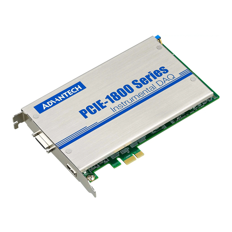
  9. Advantech PCIE-1803 Installation and operation manual

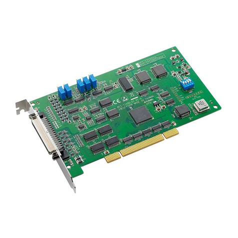
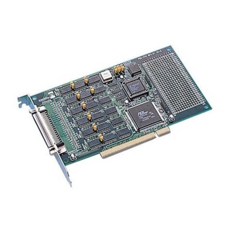
Advantech PCIE-1803 Installation and operation manual

Other manuals for PCIE-1803

1

Other Advantech PCI Card manuals

Advantech PCI-1671UP Installation and operation manual

Advantech

Advantech PCI-1671UP Installation and operation manual

Advantech PCI-1758 Series User manual

Advantech

Advantech PCI-1758 Series User manual

Advantech UNO-P166 Installation and operation manual

Advantech

Advantech UNO-P166 Installation and operation manual

Advantech MIC-5602 User manual

Advantech

Advantech MIC-5602 User manual

Advantech PCI-COMM Series User manual

Advantech

Advantech PCI-COMM Series User manual

Advantech DVP-7612HE User manual

Advantech

Advantech DVP-7612HE User manual

Advantech MIC-3950 User manual

Advantech

Advantech MIC-3950 User manual

Advantech DSPC-8661-PCXE User manual

Advantech

Advantech DSPC-8661-PCXE User manual

Advantech PCI-1761 User manual

Advantech

Advantech PCI-1761 User manual

Advantech PCI-1202 User manual

Advantech

Advantech PCI-1202 User manual

Advantech MIC-3640 User manual

Advantech

Advantech MIC-3640 User manual

Advantech PCM-28P1AD Installation and operation manual

Advantech

Advantech PCM-28P1AD Installation and operation manual

Advantech PCI-1724U User manual

Advantech

Advantech PCI-1724U User manual

Advantech PCA-6008G2 User manual

Advantech

Advantech PCA-6008G2 User manual

Advantech PCI-1752USO Installation and operation manual

Advantech

Advantech PCI-1752USO Installation and operation manual

Advantech PCI-1714 User manual

Advantech

Advantech PCI-1714 User manual

Advantech PCI-1730U Installation and operation manual

Advantech

Advantech PCI-1730U Installation and operation manual

Advantech PCIE-1754 User manual

Advantech

Advantech PCIE-1754 User manual

Advantech B+B SmartWorx McPC/Giga-MediaLinX User manual

Advantech

Advantech B+B SmartWorx McPC/Giga-MediaLinX User manual

Advantech PCI-1710U User manual

Advantech

Advantech PCI-1710U User manual

Advantech PCLD-8811 Installation and operation manual

Advantech

Advantech PCLD-8811 Installation and operation manual

Advantech PCIE-1680 User manual

Advantech

Advantech PCIE-1680 User manual

Advantech PCI-1721 User manual

Advantech

Advantech PCI-1721 User manual

Advantech PCIE-1824 User manual

Advantech

Advantech PCIE-1824 User manual

Popular PCI Card manuals by other brands

Avermedia ER330 Quick installation guide

Avermedia

Avermedia ER330 Quick installation guide

ERMA SSI 1417 instruction manual

ERMA

ERMA SSI 1417 instruction manual

SIIG CyberSerial Dual PCI Software installation

SIIG

SIIG CyberSerial Dual PCI Software installation

Airlink101 AWLH3028 user manual

Airlink101

Airlink101 AWLH3028 user manual

Dolphin MXH932 user guide

Dolphin

Dolphin MXH932 user guide

I-Bus IBC2602 user guide

I-Bus

I-Bus IBC2602 user guide

ICP DAS USA PCI-1002H user manual

ICP DAS USA

ICP DAS USA PCI-1002H user manual

Exsys EX-60102 manual

Exsys

Exsys EX-60102 manual

Chelsio Communications T5 Series Installation and user guide

Chelsio Communications

Chelsio Communications T5 Series Installation and user guide

Conrad Electronic 97 46 71 operating instructions

Conrad Electronic

Conrad Electronic 97 46 71 operating instructions

Micro Innovations USB650A Quick installation guide

Micro Innovations

Micro Innovations USB650A Quick installation guide

KTI Networks KF-310 user guide

KTI Networks

KTI Networks KF-310 user guide

Intellinet 500517 user manual

Intellinet

Intellinet 500517 user manual

Asus SpaceLink WL230 user manual

Asus

Asus SpaceLink WL230 user manual

SIIG SC2475 Quick installation guide

SIIG

SIIG SC2475 Quick installation guide

TRENDnet TEW-703PI Quick installation guide

TRENDnet

TRENDnet TEW-703PI Quick installation guide

Pericom PI7C7100 manual

Pericom

Pericom PI7C7100 manual

ADLINK Technology cPCI-3548 user manual

ADLINK Technology

ADLINK Technology cPCI-3548 user manual

manuals.online logo
manuals.online logoBrands
  • About & Mission
  • Contact us
  • Privacy Policy
  • Terms and Conditions

Copyright 2025 Manuals.Online. All Rights Reserved.

PCIE-1803 Startup Manual 1
Before installation, please make sure that you have re-
ceived the following:
• PCIE-1803 DAQ card
• Quick Start User Manual
If anything is missing or damaged, contact your distributor
or sales representative immediately.
User Manual
For more detailed information on this product, please refer
to the PCI-1803 User Manual on Advantech Support Portal:
https://support.advantech.com/support/new_default.aspx.
FCC Class A
This equipment has been tested and found to comply with
the limits for a Class A digital device, pursuant to part 15
of the FCC Rules. These limits are designed to provide
reasonable protection against harmful interference when
the equipment is operated in a commercial environment.
This equipment generates, uses, and can radiate radio fre-
quency energy and, if not installed and used in accordance
with the instruction manual, may cause harmful interference
to radio communications. Operation of this equipment in
a residential area is likely to cause interference in which
case the user is required to correct interference at his own
expense.
CE
This product has passed the CE test for environmental
specicationswhenshieldedcablesareusedforexternal
wiring. We recommend the use of shielded cables. This kind
of cable is available from Advantech. Please contact your
local supplier for ordering information.
PCIE-1803
8-ch, 24-Bit, 128 kS/s Dynamic Sig-
nal Acquisition PCI Express Card
Startup Manual
The Advantech PCIE-1803 is a high-performance data
acquisitionmodulespecicallydesignedforsoundand
vibration applications.
• AIChannels:8(simultaneouslysample,di󰀨erentialor50
Ωpseudo-di󰀨erential)
• ADCResolution:24bits(Delta-sigma)
• SampleRate:1kS/sto128kS/s(withresolution≤272.84
μS/s)
• Input Range: ±1, ±2, ±5, ±10 V
• Input Coupling: AC/DC, selectable per channel
• Input over-voltage protect
• Full auto-calibration
• Built-inanti-aliasinglter
• IEPE Excitation: Disabled, 2 mA, selectable per channel
• Board-to-board synchronization
• DIChannels:1(interrupt)
• DO Channels: 2
(Fordetailspecications,pleaserefertotheusermanualof
PCIE-1803)
General
• Bus Type: PCI Express x1
• I/O Connectors:
1x36-pinMini-SCSI(forAI),
1xHDMI(forclock,trigger,andDI/Os)
2xIDC10(forsynchronization)
• Dimensions(LxH):168x98mm(6.6”x3.9”)
• OperatingTemperature:0~70°C(32~158°F)
• StorageTemperature:-40~80°C(-40to176°F)
• StorageHumidity:5~95%RH,non-condensing
We recommend installing the driver before installing the
PCIE-1803 card to guarantee problem-free installation.
The Advantech DAQNavi Device Drivers setup program
or the PCIE-1803 can be downloaded from the Advantech
website(www.advantech.com).Followthestepsoutlined
below to install the driver software.
1. Execute the PCIE-1803 driver package.
2. The driver installation program should be launched.
When the setup program is launched, a setup screen
will be displayed.
3. Clickthe“Next”buttonandwaitfordriverinstallation.
4. Clickthe“Finish”buttontoexitthesetupprogram.
OverviewPacking List
For more information on this and other Advantech
products, please visit our website at:
http://www.advantech.com
For technical support and service, please visit our
support website at:
http://support.advantech.com
This manual is for the PCIE-1803.
Part No. 2041180300
Printed in Taiwan
1st Edition
November2019
Declaration of Conformity
Specications
Driver Installation
2 PCIE-1803 Startup Manual
1. Turno󰀨yourcomputerandunplugthepowercordandcables.TURNOFFyourcomputerbeforeinstallingorremoving
any components.
2. Remove the cover of your computer.
3. Remove the slot cover on the back panel of your computer.
4. Touch the metal part on the surface of your computer to neutralize the static electricity that might be on your body.
5. Insert the PCIE-1803 card into a PCI Express slot. Hold the card only by its edges and carefully align it with the slot. Insert
thecardrmlyintoplace.Useofexcessiveforcemustbeavoided;otherwise,thecardmightbedamaged.
6. Fasten the bracket of the PCIE-1803 card on the back panel rail of the computer with screws.
7. Connectappropriateaccessories(suchassource/syncsignalcables,wiringterminals,etc.ifnecessary)tothecard.
8. Replace the cover of your computer chassis. Re-connect the cables you removed in step 1.
9. Plug in the power cord and turn on the computer.
Hardware Installation
Block Diagram
PCIE-1803 Startup Manual 3
Refer to Figure 1 regarding the location of the connectors,
jumpers, and switches on the PCIE-1803 card.
Figure 1. PCIE-1803 Card Layout
Board ID (SW1)
ThePCIE-1803cardfeaturesabuilt-inDIPswitch(SW1)
thatisusedtodeneeachcard’sboardID.Whenmultiple
cards are installed on the same chassis, the board ID switch
isusefulforidentifyingeachcard’sdevicenumber.Afterset-
ting the ID for all PCIE-1803 cards, users can identify each
card using their various device numbers. The default board
IDvalueis0.TochangetheboardID(SW1)value,referto
the table below.
Board ID Switch Position
* Default 1 2 3 4
0* ON ON ON ON
1 ON ON ON OFF
.. .. .. .. ..
14 OFF OFF OFF ON
15 OFF OFF OFF OFF
Power On Conguration (CN1)
Thedefaultcongurationafterasystempoweronorhard-
ware reset is that all output channels are set as open (the
loadcurrentcannotbesinkingcurrent)toprotectexternal
devices from damage during system starts or resets.
However, when the system is hot reset, the status of digital
output channels is selected by jumper CN1.
ThecongurationofjumperCN1isshownbelow.
CN1 Poweroncongurationafterhotreset
Keep last status after hot reset
Defaultconguration(Defaultsetting)
Hardware Settings and Status Indicators
Connectors
MDSI (Multi-device Synchronization Interface)
The MDSI is an interface to synchronize multiple devices

with a single pacer clock generated by the master device.
CN3(input)andCN4(output)arepaireddesignforthis
purpose. Wire the cards up by daisy chain to complete the
synchronizationconnection:outputtoinput.(seeg.2)
Figure 2. Connection of Synchronization
Sensor Connection Indicators
The PCIE-1803 provides sensor connection indicators on
the upper side of CN5. It indicates if the sensor is con-
nected and working normally. Below table shows the LED
status and corresponded sensor connection. These would
only be available when IEPE is enabled.
LED Status Description
Green Normal
Orange Sensor short
O󰀨 Sensor open or no
sensor connected
Pin Assignment