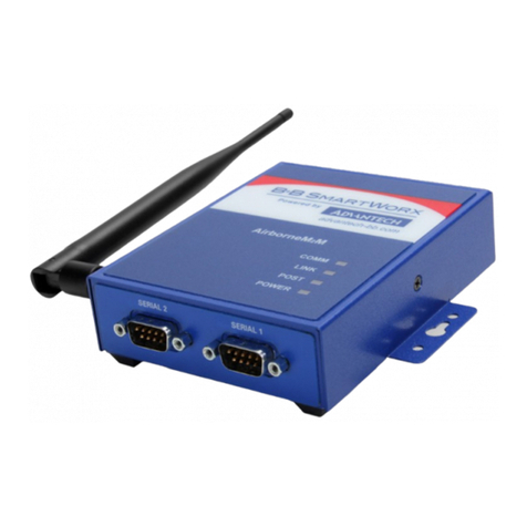
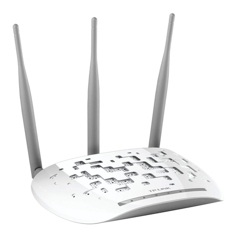
Advantech EKI-6333AC-2G Series User manual

User Manual
EKI-6333AC-2G Series
IEEE 802.11 a/b/g/n/ac WiFi AP

ii EKI-6333AC-2G Series User Manual
Copyright
The documentation and the software included with this product are copyrighted 2018
by Advantech Co., Ltd. All rights are reserved. Advantech Co., Ltd. reserves the right
to make improvements in the products described in this manual at any time without
notice. No part of this manual may be reproduced, copied, translated or transmitted
in any form or by any means without the prior written permission of Advantech Co.,
Ltd. Information provided in this manual is intended to be accurate and reliable.
However, Advantech Co., Ltd. assumes no responsibility for its use, nor for any
infringements of the rights of third parties, which may result from its use.
Acknowledgments
Intel and Pentium are trademarks of Intel Corporation.
Microsoft Windows and MS-DOS are registered trademarks of Microsoft Corp.
All other product names or trademarks are properties of their respective owners.
Product Warranty (5 years)
Advantech warrants to you, the original purchaser, that each of its products will be
free from defects in materials and workmanship for five years from the date of
purchase.
This warranty does not apply to any products which have been repaired or altered by
persons other than repair personnel authorized by Advantech, or which have been
subject to misuse, abuse, accident or improper installation. Advantech assumes no
liability under the terms of this warranty as a consequence of such events.
Because of Advantech’s high quality-control standards and rigorous testing, most of
our customers never need to use our repair service. If an Advantech product is
defective, it will be repaired or replaced at no charge during the warranty period. For
out of-warranty repairs, you will be billed according to the cost of replacement
materials, service time and freight. Please consult your dealer for more details.
If you think you have a defective product, follow these steps:
1. Collect all the information about the problem encountered. (For example, CPU
speed, Advantech products used, other hardware and software used, etc.) Note
anything abnormal and list any on-screen messages you get when the problem
occurs.
2. Call your dealer and describe the problem. Please have your manual, product,
and any helpful information readily available.
3. If your product is diagnosed as defective, obtain an RMA (return merchandise
authorization) number from your dealer. This allows us to process your return
more quickly.
4. Carefully pack the defective product, a fully-completedRepair and Replacement
Order Card and a photocopy proof of purchase date (such as your sales receipt)
in a shippable container. A product returned without proof of the purchase date
is not eligible for warranty service.
5. Write the RMA number visibly on the outside of the package and ship it prepaid
to your dealer.
Part No. Edition 1
Printed in Taiwan January 2020

EKI-6333AC-2G Series User Manual iii
Declaration of Conformity
CE
This product has passed the CE test for environmental specifications. Test conditions
for passing included the equipment being operated within an industrial enclosure. In
order to protect the product from being damaged by ESD (Electrostatic Discharge)
and EMI leakage, we strongly recommend the use of CE-compliant industrial
enclosure products.
FCC Class B
This equipment has been tested and found to comply with the limits for a Class B
digital device, pursuant to Part 15 of the FCC Rules. These limits are designed to
provide reasonable protection against harmful interference in a residential
installation. This equipment generates, uses and can radiate radio frequency energy
and, if not installed and used in accordance with the instructions, may cause harmful
interference to radio communications. However, there is no guarantee that
interference will not occur in a particular installation. If this equipment does cause
harmful interference to radio or television reception, which can be determined by
turning the equipment off and on, the user is encouraged to try to correct the
interference by one of the following measures:
Reorient or relocate the receiving antenna.
Increase the separation between the equipment and receiver.
Connect the equipment into an outlet on a circuit different from that to which the
receiver is connected.
Consult the dealer or an experienced radio/TV technician for help.
FCC Caution: Any changes or modifications not expressly approved by the party
responsible for compliance could void the user's authority to operate this equipment.
This device complies with Part 15 of the FCC Rules. Operation is subject to the
following two conditions: (1) This device may not cause harmful interference, and (2)
this device must accept any interference received, including interference that may
cause undesired operation.
FCC RF Radiation Exposure Statement:
1. This Transmitter must not be co-located or operating in conjunction with any
other antenna or transmitter.
2. This equipment complies with FCC RF radiation exposure limits set forth for an
uncontrolled environment. Thisequipment should be installed and operated with
a minimum distance of 20 centimeters (7.87 inches) between the radiator and
your body.

iv EKI-6333AC-2G Series User Manual
Technical Support and Assistance
1. Visit the Advantech web site at www.advantech.com/support where you can find
the latest information about the product.
2. Contact your distributor, sales representative, or Advantech's customer service
center for technical support if you need additional assistance. Please have the
following information ready before you call:
–Product name and serial number
–Description of your peripheral attachments
–Description of your software (operatingsystem, version, application software,
etc.)
–A complete description of the problem
–The exact wording of any error messages
Warnings, Cautions and Notes
Document Feedback
To assist us in making improvements to this manual, we would welcome comments
and constructive criticism. Please send all such - in writing to:
Warning! Warnings indicate conditions, which if not observed, can cause personal
injury!
Caution! Cautions are included to help you avoid damaging hardware or losing
data. e.g.
There is a danger of a new battery exploding if it is incorrectly installed.
Do not attempt to recharge, force open, or heat the battery. Replace the
battery only with the same or equivalent type recommended by the
manufacturer. Discard used batteries according to the manufacturer's
instructions.
Note! Notes provide optional additional information.

EKI-6333AC-2G Series User Manual v
Packing List
Before setting up the system, check that the items listed below are included and in
good condition. If any item does not accord with the table, please contact your dealer
immediately.
1 x WiFi AP
1 x DIN Rail Bracket and Screws
1 x Wall-mounting Bracket
2 x Antennas
Safety Instructions
Read these safety instructions carefully.
Keep this User Manual for later reference.
This device is for indoor use only.
Disconnect this equipment from any DC outlet before cleaning. Use a damp
cloth. Do not use liquid or spray detergents for cleaning.
For plug-in equipment, the power outlet socket must be located near the
equipment and must be easily accessible.
Keep this equipment away from humidity.
Put this equipment on a reliable surface during installation. Dropping it or letting
it fall may cause damage.
The openings on the enclosure are for air convection. Protect the equipment
from overheating. DO NOT COVER THE OPENINGS.
Make sure the voltage of the power source is correct before connecting the
equipment to the power outlet.
Position the power cord so that people cannot step on it. Do not place anything
over the power cord.
All cautions and warnings on the equipment should be noted.
If the equipment is not used for a long time, disconnect it from the power source
to avoid damage by transient overvoltage.
Never pour any liquid into an opening. This may cause fire or electrical shock.
Never open the equipment. For safety reasons, the equipment should be
opened only by qualified service personnel.
If one of the following situations arises, get the equipment checked by service
personnel:
–The power cord or plug is damaged.
–Liquid has penetrated into the equipment.
–The equipment has been exposed to moisture.
–The equipment does not work well, or you cannot get it to work according to
the user's manual.
–The equipment has been dropped and damaged.
–The equipment has obvious signs of breakage.
DO NOT LEAVE THIS EQUIPMENT IN AN ENVIRONMENT WHERE THE
STORAGE TEMPERATURE MAY GO -40°C (-40°F) ~ 80°C (176°F). THIS
COULD DAMAGE THE EQUIPMENT. THE EQUIPMENT SHOULD BE IN A
CONTROLLED ENVIRONMENT.
The sound pressure level at the operator's position according to IEC 704-1:1982
is no more than 70 dB (A).
DISCLAIMER: This set of instructions is given according to IEC 704-1.
Advantech disclaims all responsibility for the accuracy of any statements
contained herein.

vi EKI-6333AC-2G Series User Manual
Safety Precaution - Static Electricity
Static electricity can cause bodily harm or damage electronic devices. To avoid
damage, keep static-sensitive devices in the static-protective packaging until the
installation period. The following guidelines are also recommended:
Wear a grounded wrist or ankle strap and use gloves to prevent direct contact to
the device before servicing the device. Avoid nylon gloves or work clothes,
which tend to build up a charge.
Always disconnect the power from the device before servicing it.
Before plugging a cable into any port, discharge the voltage stored on the cable
by touching the electrical contacts to the ground surface.
About the Device
This device is for indoor use only.

EKI-6333AC-2G Series User Manual 1
Contents
Chapter 1 Introduction......................................... 1
1.1 Overview................................................................................................... 2
1.2 Device Features........................................................................................ 2
1.3 Specifications............................................................................................ 2
1.4 Dimensions............................................................................................... 4
Chapter 2 Getting Started.................................... 5
2.1 Hardware .................................................................................................. 6
2.1.1 Front View..................................................................................... 6
2.1.2 Rear View..................................................................................... 7
2.1.3 Top View....................................................................................... 7
2.1.4 Bottom View.................................................................................. 8
2.1.5 Right View..................................................................................... 8
2.1.6 Left View....................................................................................... 9
2.1.7 LED Indicators............................................................................ 10
2.2 Connecting Hardware............................................................................. 11
2.2.1 Wall Mounting............................................................................. 11
2.2.2 Wireless Connection................................................................... 12
2.2.3 Network Connection ................................................................... 14
2.2.4 Power Connection ...................................................................... 14
2.3 Reset Button........................................................................................... 16
Chapter 3 Web Interface ....................................18
3.1 Log In...................................................................................................... 19
3.1.1 Password.................................................................................... 20
3.2 Overview................................................................................................. 20
3.3 Interface Settings.................................................................................... 22
3.3.1 LAN............................................................................................. 22
3.3.2 WAN ........................................................................................... 23
3.3.3 Wireless 2.4GHz......................................................................... 25
3.3.4 Wireless 5GHz............................................................................ 37
3.4 Network Settings..................................................................................... 38
3.4.1 Static Route................................................................................ 38
3.4.2 Forwarding.................................................................................. 38
3.5 Management........................................................................................... 40
3.5.1 Password Manager..................................................................... 40
3.5.2 Syslog......................................................................................... 40
3.5.3 NTP / Time.................................................................................. 42
3.5.4 SNMP ......................................................................................... 43
3.5.5 Remote Services ........................................................................ 44
3.5.6 Configuration Manager............................................................... 45
3.5.7 Firmware Upgrade...................................................................... 45
3.5.8 Reset System ............................................................................. 45
3.5.9 Apply Configuration .................................................................... 46
3.5.10 Reboot Device............................................................................ 46
3.6 Tools....................................................................................................... 47
3.6.1 Diagnostics................................................................................. 47

2 EKI-6333AC-2G Series User Manual
List of Figures
Figure 1.1 Dimensions....................................................................................................................4
Figure 2.1 Front View .....................................................................................................................6
Figure 2.2 Rear View......................................................................................................................7
Figure 2.3 Top View........................................................................................................................7
Figure 2.4 Bottom View ..................................................................................................................8
Figure 2.5 Right View .....................................................................................................................8
Figure 2.6 Left View........................................................................................................................9
Figure 2.7 System LED Panel ......................................................................................................10
Figure 2.8 Mounting Screw Installation.........................................................................................11
Figure 2.9 Wall Mount Installation ................................................................................................12
Figure 2.10 Installing the Top Antennas.........................................................................................12
Figure 2.11 Installing the Bottom Antennas....................................................................................13
Figure 2.12 Positioning the Antenna...............................................................................................13
Figure 2.13 Ethernet Plug & Connector Pin Position......................................................................14
Figure 2.14 Connecting Power to the PoE LAN Port......................................................................15
Figure 2.15 Grounding Connection.................................................................................................16
Figure 2.16 Reset Button Location .................................................................................................17
Figure 3.1 Login Screen ...............................................................................................................19
Figure 3.2 Administration > HTTP ................................................................................................20
Figure 3.3 Overview, System Info and LAN Interface...................................................................20
Figure 3.4 Overview, WAN Interface, DHCP Leases, and System Status ...................................21
Figure 3.5 Interface > LAN..........................................................................................................22
Figure 3.6 Interface > WAN > Network Mode...............................................................................23
Figure 3.7 Interface > WAN > Network Mode > Static..................................................................24
Figure 3.8 Interface > WAN > Network Mode...............................................................................24
Figure 3.9 Interface > WAN > Network Mode > PPPoE...............................................................25
Figure 3.10 Wireless - 2.4GHz > Basic > Access Point..................................................................26
Figure 3.11 Wireless - 2.4GHz > Basic > Client.............................................................................27
Figure 3.12 Wireless - 2.4GHz > Basic > Bridged Repeater..........................................................28
Figure 3.13 Wireless - 2.4GHz > Advanced ...................................................................................30
Figure 3.14 Wireless - 2.4GHz > Advanced ...................................................................................31
Figure 3.15 Wireless - 2.4GHz > Security ......................................................................................32
Figure 3.16 Wireless - 2.4GHz > Security ......................................................................................32
Figure 3.17 Wireless - 2.4GHz > Multiple SSID..............................................................................33
Figure 3.18 Wireless - 2.4GHz > QoS............................................................................................34
Figure 3.19 Wireless - 2.4GHz > Statistics.....................................................................................35
Figure 3.20 Wireless - 2.4GHz > Access Control...........................................................................36
Figure 3.21 Wireless - 2.4GHz > Site Survey.................................................................................36
Figure 3.22 Wireless - 2.4GHz > Log .............................................................................................37
Figure 3.23 Networking > Static Route..........................................................................................38
Figure 3.24 Networking > Forwarding > Port Forwarding............................................................38
Figure 3.25 Networking > Forwarding > DMZ...............................................................................39
Figure 3.26 Management > Password Manager...........................................................................40
Figure 3.27 Management > Syslog................................................................................................41
Figure 3.28 Management > NTP / Time......................................................................................... 42
Figure 3.29 Management > SNMP................................................................................................43
Figure 3.30 Management > Remote Services..............................................................................44
Figure 3.31 Management > Configuration Manager .....................................................................45
Figure 3.32 Management > Firmware Upgrade.............................................................................45
Figure 3.33 Management > Apply Configuration........................................................................ 45
Figure 3.34 Management > Apply Configuration........................................................................ 46
Figure 3.35 Management > Reboot Device.................................................................................. 46
Figure 3.36 Tools > Diagnostics ....................................................................................................47

Chapter 1
1Introduction

2 EKI-6333AC-2G Series User Manual
1.1 Overview
The EKI-6333AC-2G Series The EKI-6333AC-2G Series is a feature rich wireless AP
which provides a reliable wireless connectivity for industrial environments. The PoE
injector enhances flexibility in deployment of this AP even where the DC power
supply is hard to fulfill. As an 802.11n compliant device, EKI-6333AC-2G provides 6
times higher data rates than legacy 802.11g devices.
With the support of STP, WMM and IGMP snooping protocols, EKI-6333AC-2G
effectively improves the reliability of wireless connectivity, especially in applications
that need high reliability and high throughput data transmission. To secure wireless
connections, EKI-6333AC-2G implements the latest encryption technologies
including WPA2/WPA/802.1x for powerful security authentication.
1.2 Device Features
Support 802.11n MIMO 2T2R
WLAN transmission rate up to 867 Mbps
Supports secure access with WEP, 802.1x, WPA/WPA2-Personal, WPA/WPA2-
Enterprise
Provides Web-based configuration
Support Dual band 2.4G/5G Concurrent
IP55 waterproof certification
1.3 Specifications
Specifications Description
Interface I/O Port 2 x RJ45
Power Connector RJ45, Passive 24V PoE
Physical Enclosure Plastic
Mounting Wall, pole
Dimensions
(W x H x D) 191.6 x 114.3 x 47.7 mm (7.54” x 4.49” x 1.88”)
Weight TBD
LED Display System LED System: Power
WLAN: Link/Active
LAN: Link/Active
Reboot Trigger Built-in WDT (watchdog timer)
Environment Operating
Temperature -20 ~ 70 °C (-4~158°F)
Storage
Temperature -30 ~ 80°C (-22 ~ 176°F)
Ambient Relative
Humidity 10 ~ 95% RH

EKI-6333AC-2G Series User Manual 3
Wireless LAN
Communications Compatibility 2.4GHz: IEEE 802.11 b/g/n
5GHz: IEEE 802.11 a/n/ac
Speed Up to 867 Mbps
Network Mode Infrastructure
Free Space
Range Open space 100 m
Antenna 4 x Reverse SMA connectors
Default external 5 dBi Omni antenna
Wireless Security WEP, WPA/WPA2-Personal, WPA/WPA2-Enterprise
Ethernet
Communications Compatibility IEEE 802.11a/b/g/n/ac
Speed 10/100/1000 Mbps
Port Connector 2 x 8-pin RJ45
Protection Built-in 1.5 KV magnetic isolation
Power Power
Consumption TBD
Power Input DC 24V / 1A
Software Management Telnet, FTP, SNMP, Web UI, SSH
Wireless Radio on/off, WMM/Regatta Mode, Output Power
Control, Beacon Interval, RTS/ CTS threshold, DTIM
Interval
Operation Modes Access Point mode, Client, Repeater
Configuration Web Browser
Protocol ARP, ICMP, IPv4, IPv6, TCP, UDP, DHCP Client,
DHCP Server, Auto IP, Telnet, DNS, SNMP, HTTP,
DMZ, PPPoE, DHCP server, VPN Passthrough,
Telnet Server, SSH Server, FTP Server, QoS
Regulatory
Approvals EMC CE, FCC Part 15 Subpart B (Class B)
Specifications Description

4 EKI-6333AC-2G Series User Manual
1.4 Dimensions
Figure 1.1 Dimensions
93.96 [3.699]
47.71 [1.878]
191.74 [7.549]
114.33 [4.501]

Chapter 2
2Getting Started

6 EKI-6333AC-2G Series User Manual
2.1 Hardware
2.1.1 Front View
Figure 2.1 Front View

EKI-6333AC-2G Series User Manual 7
2.1.2 Rear View
Figure 2.2 Rear View
2.1.3 Top View
Figure 2.3 Top View
No. Item Description
1. Quick mount keyhole
slot Slots for mounting device to a wall
1
1
No. Item Description
1. Antenna connector Reverse SMA connector for 5G WLAN antenna
2. Antenna connector Reverse SMA connector for 2G WLAN antenna
21

8 EKI-6333AC-2G Series User Manual
2.1.4 Bottom View
Figure 2.4 Bottom View
2.1.5 Right View
Figure 2.5 Right View
No. Item Description
1. ETH port LAN2 RJ45 port
2. Antenna connector Reverse SMA connector for 2G WLAN antenna
3. ETH port LAN1 RJ45 port, supports PoE
4. Antenna connector Reverse SMA connector for 5G WLAN antenna
5. Reset button Button allows for system soft reset or factory default reset
2
43
1
5

10 EKI-6333AC-2G Series User Manual
2.1.7 LED Indicators
Figure 2.7 System LED Panel
No. LED Name LED Color Description
1. WLAN (5Ghz) Green on Wireless function is active
Green blinking Wireless port is transmitting or receiving data
2. Ethernet
(LAN 2) Green on 10/100/1000Mbps Ethernet connection
Green blinking Ethernet port is transmitting or receiving data
3. PWR Amber on Power is on
Amber blinking Boot state
Off Power is off or power error condition exists
4. Ethernet
(LAN 1) Green on 10/100/1000Mbps Ethernet connection
Green blinking Ethernet port is transmitting or receiving data
5. WLAN
(2.4Ghz) Green on Wireless function is active
Green blinking Wireless port is transmitting or receiving data
LAN 1
PWR
LAN 2
5GHz
2.4GHz
1
5
2
3
4

EKI-6333AC-2G Series User Manual 11
2.2 Connecting Hardware
2.2.1 Wall Mounting
This section provides instructions for installing the access point. It is recommended
that only personnel with an understanding of wireless access points and bridging
techniques and grounding methods install the device.
When mounting an access point, make sure the access point is oriented with the LED
indicators clearly visible.
In addition, the access point must be mounted in such a way as to ensure that all
antenna ports and the console port are accessible for future use.
1. On the installation site, place the device firmly against the wall. Make sure the
device is vertically and horizontally level.
2. Use the location of the keyhole slots on the back of the device to mark two
screw hole locations on the mounting surface.
3. Remove the device from the wall and drill holes over each marked location (2)
on the wall, keeping in mind that the holes must accommodate wall sinks in
addition to the screws.
4. Insert the wall sinks into the walls.
5. Insert a screw in a wall sink and rotate it to secure. Do not tighten at this point.
Repeat for the remaining location, see the following figure.
Figure 2.8 Mounting Screw Installation
6. Align the keyhole slots over the screws and insert the device in place.
Warning! The installation of the access point must comply with local and national
electrical codes.
Note! When installing, make sure to allow for enough space to properly install
the cabling.

12 EKI-6333AC-2G Series User Manual
7. Slide the device down to sit it securely in the mounting screws.
Figure 2.9 Wall Mount Installation
2.2.2 Wireless Connection
1. Connect the top antennas by turning the antenna in the connectors in a
clockwise direction.
Figure 2.10 Installing the Top Antennas
1
1 2
Note! The location and position of the antenna is crucial for effective wireless
connectivity
Table of contents
Other Advantech Wireless Access Point manuals
Advantech
Advantech EKI-6333AC-M12 Series User manual
Advantech
Advantech EKI-6333AC-A Series User manual

Advantech
Advantech OW-1000A User manual

Advantech
Advantech WLAN-9100 User manual
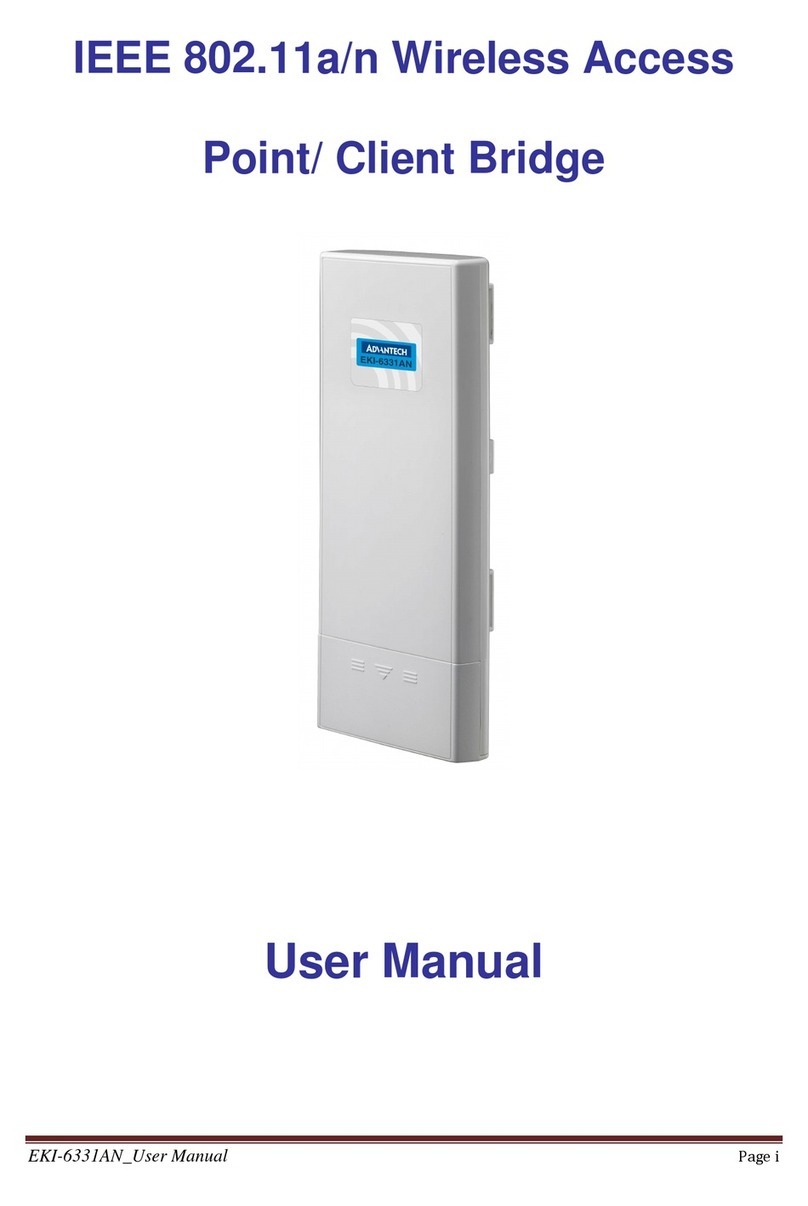
Advantech
Advantech IEEE 802.11a/n Wireless Access Point/ Client... User manual
Advantech
Advantech EKI-6340 Series User manual
Advantech
Advantech EKI-6333AC-2GD Series User manual
Advantech
Advantech EKI-6311G User manual
Advantech
Advantech EKI-6333AC-4GP User manual
Advantech
Advantech EKI-6321AG User manual

