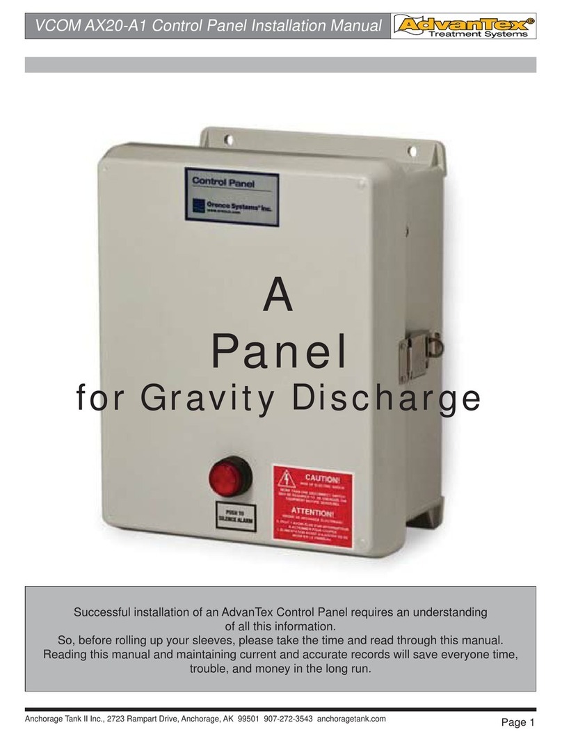
AdvanteX VCOM AX20-B User manual

VCOM AX20-B Control Panel Installation Manual
VeriComm AX20-B Control Panel
for Pumped Discharge
Successful installation of an AdvanTex Control Panel and the wiring requires an
understanding of all this information. So, before getting started, please take the
time and read through this manual. Reading this manual and maintaining
current and accurate records will save everyone time, trouble, and money in the
long run. Call the office if you have any questions.
Page 1

VCOM AX20-B Control Panel Installation Manual
Installing the Control Panel
On the inside of the control panel door, you will find a label that
shows the model number and the six-digit RTU number. (RTU
stands for remote telemetry unit). The RTU number is the identity of
the system for as long as it is in operation. This is a big deal
because if you are installing and taking possession of more than
one system at a time, it is easy to simply grab the first panel you
find, which means it may end up at the wrong house. AQWA, Inc.
makes the RTU / address assignments as systems are sold so if
you need assistance please call AQWA, Inc. Imagine how much
fun it is to have a control panel “report in” with an issue and the
Service Provider shows up at the wrong house where nothing is
wrong.
KEY POINT: The control Panel has a distinct identity and has been
assigned to the address of that particular job site!
Placement of the Control Panel
Each site is different but the rule of thumb is that the physical
installation of the Control Panel should be within view of the tank &
AdvanTex filter, at a convenient height, normally with the top of the
panel set at 5 ft above final grade.
The Control Panel contains motor contactors that make a clunking
sound each time the pump is activated. If the Panel is attached to
the wall of a house, it can clearly be heard from inside the house,
particularly in the middle of the night. With that in mind it is
preferable to mount the panel on two treated 4x4 posts with 2X4
mounting boards right next to the wall.
IMPORTANT: Do NOT place the Control Panel inside the home!
The idea is for the Service Provider to access the panel for
maintenance and emergency situations and NOT require the
homeowner to be present. The panel is designed to be located
outside!
Page 2

VCOM AX20-B Control Panel Installation Manual
Installing the Control Panel - Floats and Pumps
Power cords for the floats and pumps should be pulled through the cord grips from inside the access
riser to the inside of the splice box. Pull enough cord to allow the cords to extend 6” outside the
access lid on the top of the external splice box shown below. This allows for the splices and wire nuts
to be maintained in the years ahead. Tighten the cord grips around the float and pump cords so that
they can no longer be pulled and will prevent sewage or gasses from seeping into the external splice
box. Each of the cord grips should have either a cord or dummy plug (provided) secured in the grip.
Test the tightness of the cord grips by pulling on each wire to ensure that they are tight.
Wiring between the external splice boxes and control panel should be run in either ¾” or 1” conduit.
Use sweep 90 elbows to connect to the bottom connector of the external splice box and below grade
beneath the control panel. Install/solvent weld the conduit plug (provided) in the unused socket of the
external splice box if only one conduit is required. Hard conduit is required for the complete length of
the electrical runs with solvent welds at each connection. Use standard conduit adapters and lock
rings inside the bottom of the panel. DO NOT DRILL PENETRATIONS INTO THE PANEL ON THE
TOP, SIDES, OR BACK OF THE PANEL – BOTTOM PENETRATIONS ONLY.
When wiring between the panel and the external splice boxes, use 14 gauge stranded copper wire for
float wires. Use the supplied blue lithium wire nuts to tie float neutrals together at the external splice
box and run a single neutral to the control panel. Use 12 gauge twisted copper wire for the pump(s)
with black (load), white (neutral), and green (ground) wires. Additionally it is useful to pull an extra
wire (“pull wire”) through the conduit. Leave 6”- 8” of wire length inside the panel to connect to the
terminal strip so that all connections are easily accessed and maintained. Wire that is improperly
sized (too small) can cause excessive voltage drop, poor pump performance, and premature failure,
so please only use the specified wire gauge/sizes. Splices that are not waterproof will cause
malfunction of the pump and controls if water should leak into the splice box. Splice box female
threads and lids should be clean and tightened enough to compress the O’ring in the lid to prevent
water penetration.
Page 3

VCOM AX20-B Control Panel Installation Manual
***Properly connected wire nuts should not be easily removed, gently pull on each wire nut
after installation. If the wirenut pulls free, it must be redone. Only waterproof wire nuts to be
used.***
Connection to the House Electrical Panel -
Electrical runs from the home electrical panel should always be made by a licensed electrician in
coordination with the home builder. (3) Independent circuits are required from the home’s electrical
panel. One for the CONTROL breaker (always 120V) and two others for the pumps (typ. 120V but
may be 230V). Power supply wiring from the house is to be pulled through the penetrations in the
lower right bottom of the panel where the control panel, incoming power circuit breakers are located.
See “Incoming Power” shown below. Penetrations for the electrical runs from the external splice
boxes will be on the bottom left of the control panel (recirculation pump and floats on the leftmost and
discharge/dose pump(s) and floats to the immediate right of the recirc conduit connection as shown
below.
For Automatic drip panels with solenoids located in a drip headworks unit additional wiring will be required. For
Single Zone and Two Zone automatic drip systems, (1) 1-in conduit will be run to the splice box located on the
headworks. (2) sets of 14 gauge wire to be supplied to each solenoid. Single Zone headworks contain (2)
solenoid valves. Two Zone headworks contain (4) solenoid valves.
Page 4

VCOM AX20-B Control Panel Installation Manual
Connecting Float and Pump wires to the Control Panel
Connect the wires coming from the recirc and discharge external splice boxes to the numbered
terminal points in the Control Panel. Refer to the appropriate Float & Splice Box Wiring Diagram for
the correct terminal locations for your system. For the AX20-B Control Panel the wiring is as follows:
Terminal Point No. Float Function/Location on Float Stem
1 Recirc bottom float, Timer Enable/Redundant OFF
2 Recirc middle float, Override ON
3 Recirc HLA
4 Recirc Float neutral/commons
5 Recirc Pump Load wire (black)
6 Recirc Pump Neutral (white)
11 Discharge bottom float, OFF
12 Discharge middle float, ON
13 Discharge top float, HLA Override ON
14 Discharge Float neutral/commons (white)
15 Discharge pump load (black)
16 Discharge pump neutral (white)
Ground lugs Recirc and Discharge pump ground wires (green)
17 Spin Filter (If applicable)
18 Spin Filter (If applicable)
19 Field Flush (If applicable)
20 Field Flush (If applicable)
21 Zone1 (If applicable)
22 Zone1 (If applicable)
23 Zone2 (If applicable)
24 Zone2 (If applicable)
25 Zone3 (If applicable)
26 Zone3 (If applicable)
27 Zone4 (If applicable)
28 Zone4 (If applicable)
A Wiring diagram is provided with every control panel that is sold. Please reference the wiring
diagram provided with your panel if you have any questions or suspect that it differs from the
examples included in this document.
KEY POINTS:
● Voltage for the controls in the panel is always 120 VAC, although the pump voltage may
be 120 VAC or 240 VAC depending on the pump voltage.
● All wire nut connections should be tested by gently pulling on the wirenut, if the
connection is solid, the wire nut will not pull off. If the wire nut pulls loose, the
connection is not good and should be redone with a fresh, waterproof wire nut.
●
Page 5

VCOM AX20-B Control Panel Installation Manual
● All terminal connections should be tested after connection is made by gently pulling on
the wire. If the connection is solid, the wire should not pull out of the terminal
connection.
● Ensure that the panel is properly grounded and that the breaker and wire size, from the
main power panel to the pump, are correctly sized. A separate circuit for the pump
controls and each of the pump motors is essential to sustained operations.
● Do not service the pump or any electrical wiring in the pump vault without disconnecting
the power at the circuit breaker(s).
● Serious injury and/or damage to the system could result if the panel is not properly
grounded. Ensure that the fuse, breaker, and wire size, from the main power panel and
to the pump, are sized correctly.
● The pump vault is a hazardous area and may contain explosive gasses. Take
appropriate precautions according to local, state, and federal regulations before
commencing work in the pump vault.
● It is the responsibility of the installer to comply with all local, state, and federal
regulations that may govern the installation of systems of this nature. Failure to comply
with such regulations may void the manufacturer’s warranty and could possibly cause
bodily injury.
Connecting for Remote Monitoring
To support remote monitoring of the system, the VeriComm Control Panels have the option to utilize a
common phone line or a high speed Ethernet connection (CAT5). You will need to check with the
homeowner or builder to determine which connection method is available or desired.
Should they decide on a regular phone line, please be aware these panels do not need a
dedicated phone line, only an extension of an existing line. Some panels are only equipped for
Ethernet connections, without a phone surge arrester or phone jack. In this case, follow the directions
below. If you prefer a regular phone connection or your property has an elevator (which requires a
phone), call AQWA, and the proper equipment can be purchased.
Installation of a traditional copper-wire analog telephone line is straight-forward. You’ll notice a phone
jack connection in the middle of the control panel. A DSL line filter/surge arrester is also installed.
Once you have a dial tone at the end of this phone line, just plug in the phone clip (RJ11) and you’re
good to go.
Page 6

VCOM AX20-B Control Panel Installation Manual
Ethernet connections require an Ethernet cable (CAT5) run from the House Internet Router Ethernet
port to the control panel to connect to the Nport or Lantronics equipment mounted on the inside of the
control panel door. The cable must be uncut and unspliced from the panel to the Router port. The
CAT5 should be run with extra cable to allow for Router location adjustments and 12” of extra wire
coiled inside the control panel. The RJ45 connection pattern is specified by the Cable/Internet Service
Provider, but they most commonly use an AT&T connection pattern. Both ends must match
identically for the connection to work. These connections are typically installed by an electrician or
private communications company. See below:
We hope this guide makes the installation of the wiring for the control panel, float sensors, pumps,
and communications clear and easy to do. If you have any questions, please give us a call at the
number below.
Page 7
Table of contents
Other AdvanteX Control Panel manuals
Popular Control Panel manuals by other brands

SILENT KNIGHT
SILENT KNIGHT 5207 Installation, programming, and operation manual

HESA
HESA HFA-2000 operating instructions
Harman
Harman MODERO X Series Installation & hardware reference manual
Alarm Sense
Alarm Sense CFP 8 ZONE user manual

Spectron
Spectron BM55-2U operating manual

Fire-Lite Alarms
Fire-Lite Alarms MS-9600LS manual


