AdvanteX VCOM AX20-A1 User manual

Anchorage Tank II Inc., 2723 Rampart Drive, Anchorage, AK 99501 907-272-3543 anchoragetank.com Page 1
VCOM AX20-A1 Control Panel Installation Manual
Successful installation of an AdvanTex Control Panel requires an understanding
of all this information.
So, before rolling up your sleeves, please take the time and read through this manual.
Reading this manual and maintaining current and accurate records will save everyone time,
trouble, and money in the long run.
A
Panel
for Gravity Discharge

Anchorage Tank II Inc., 2723 Rampart Drive, Anchorage, AK 99501 907-272-3543 anchoragetank.com
Page 2
VCOM AX20-A1 Control Panel Installation Manual
Installing the Control Panel
In the Municipality ofAnchorage, an electrician must be employed to do the
wiring. Outside the city, whether required or not, this is a good idea unless
one is thoroughly familiar with wiring and local codes.
Key Point: Thecontrolpanelhasadistinctidentityandhas
been assigned to the address of that particular
job site.
On the inside of the control panel door, you will find a label that shows
the model number and a six-digit RTU number. (RTU stands for Remote
Telemetry Unit). The RTU number is the identity of the system for as
long as it is in operation. Why is this a big deal to you? Well... if you are
installing and taking possession of more than one system at a time, it is
easy to simply grab the first panel you find... and it may end up at the
wrong house! Anchorage Tank makes the RTU / address assignments
as systems are sold so if you get confused - please callAnchorage Tank.
This has happened before. Imagine how much fun it is to have a control
panel “phone home” with an issue and the Service Provider shows up at
the wrong house where nothing is wrong.
Placement of the Control Panel
There has been a lot of debate where to place the Control Panel. Each site
is different but the rule of thumb is that the physical installation of the Con-
trol Panel should be within view of the Tank & Filter, at a convenient height,
usually 5 feet above grade.
The Control Panel contains motor contactors that make a clunking sound
each time the pump is activated. If the Panel is attached to the wall of a
house, it sounds like a moose kicking the wall every twenty minutes. With
that in mind, it is preferable to mount the Panel on a treated 4x6 post right
next to the wall.
The Control Panel should NOT be placed
inside the home. The idea is for the Service
Providertoaccessthepanelformaintenance
and emergency situations and NOT bother
the homeowner.
Initially it may sound good to have the panel
locatedindoors but it actually isn’t. Thepanel
is designed to be located outside.
IMPORTANT:
4 x 6

Anchorage Tank II Inc., 2723 Rampart Drive, Anchorage, AK 99501 907-272-3543 anchoragetank.com Page 3
VCOM AX20-A1 Control Panel Installation Manual
Installing the Control Panel
Floats and Pumps
Do not remove the colored
markers or the paper tags from the
float cords. These should be left
on the float cord, outside the splice
box.
Do not thread the markers and
tags through the cord grips.
Adequate length of cord should
be left within the splice box to allow
for easy removal for future discon-
necting and re-splicing.
Wire that is improperly sized
(too small) can cause excessive
voltage drop, poor pump perfor-
mance, and premature failure.
Splices that are not waterproof
will cause malfunction of the pump
controls if water should leak into
the splice box.
We’ve seen it happen.
Key Points: At this point, the floats and pump is in place and their wires have
been stabbed into the splice box.
Just in case they aren’t, thread the float and pump cords through
the cord grips into the PVC splice box, leaving adequate length of
electrical cord coiled inside the riser to allow easy removal of the
pump and float assembly. Tighten the cord grips by hand and then
check the tightness by tugging on each cord.
The wires from the Control Panel to the splice box should be run
in conduit. A conduit seal should be used to prevent infiltration
of water into the splice box. The number of wires depends upon
the number of pumps and floats, but most 3-float 1-pump systems
use 2 runs of 3-wire 12 GA direct-burial. That gives you a total of 6
wires and two bare grounds.
All splices made in the splice box should use waterproof wire nuts
or butt connectors and heat shrink tubing.
At the home’s electrical panel, you will use two 20 amp
breakers, one for the control side of the panel and the
other for the pump side.
HANDY HINT
Don’t forget the remote alarm. This
connects to the control panel using
phone wire and is normally placed
inside the garage.
The remote alarm is a code require-
ment.
IMPORTANT:

Anchorage Tank II Inc., 2723 Rampart Drive, Anchorage, AK 99501 907-272-3543 anchoragetank.com
Page 4
VCOM AX20-A1 Control Panel Installation Manual
Connecting to the Control Panel
Connect the wires coming from the floats to the terminals in the Control
Panel. Refer to the appropriate Float & Splice Box Wiring Diagram for the
correct terminal locations for your system.
Connect the wire coming from your pump to the pump terminal. The Panel
WiringDiagramwilldisplay the correct terminal connections for your system.
Connect the incoming power to the panel. Power to the panel must be ap-
propriate to the Control Panel and pump motor e.g., 120 VAC, single phase
for a 120 VAC motor, 240 VAC single phase for a 240 VAC motor, etc.)
Ensure that the panel is properly grounded and that the fuse or breaker
and wire size, from the main power panel to the pump, are correctly sized.
A separate circuit for the pump controls and each of the pump motors is
recommended.
Note: Voltage for the controls in the panel is always 120 VAC, although
the pump voltage may be 120 VAC or 240 VAC.
Use 600 CU conductors only. Torque to the following: Terminal blocks @ 15
LB-IN. Circuit breaker @ 20 LB-IN and ground lugs @ 45 LB-IN.
Do not service the pump or any elec-
trical wiring in the pump vault without
disconnecting the power at the circuit
breaker and/or fuse.
Serious injury and/or damage to the
system could result if the panel is not
properly grounded. Ensure that the
fuse, breaker, and wire size, from the
main power panel and to the pump,
are sized correctly.
The pump vault is a hazardous area
and may contain explosive gas-
es. Take appropriate precautions
according to local, state, and federal
regulations before commencing work
in the pump vault.
It is the responsibility of the installer
to comply with all local, state, and
federal regulations that may govern
the installation of systems of this
nature. Failure to comply with such
regulations may void the manufac-
turer’s warranty and could possibly
cause bodily injury.
Key Points:
To permit remote monitoring of the system, the VeriComm Control Panels have the option to utilize a common phone
line or a high speed internet connection. You will need to check with the homeowner to determine which connection
method is available or desired.
Should they decide on a regular phone line, please be aware these panels do not need a dedicated phone line,
merely an extension of an existing line.
Installation of a tradional copper-wire analog telephone line is straight-forward. You’ll notice a phone jack connection in
the middle of the control panel. A DSL line filter/surge arrestor is also installed. Once you have a dial tone at the end of
this phone line, just plug it in and you’re good to go.
Digital connections (internet) will require an ethernet cable run from the House Internet Router out to the control
panel to connect to the Lantronics equipment mounted on the inside of the control panel door.
Connecting for Remote Monitoring

Anchorage Tank II Inc., 2723 Rampart Drive, Anchorage, AK 99501 907-272-3543 anchoragetank.com Page 5
VCOM AX20-A1 Control Panel Installation Manual
Control Panel Wiring Diagram
Model VCOM-AX20A1 RA IP
Pump
115 VAC / 1 Hp.
1 Phase / 60 Hz.
EDW-WD-AX-121
Rev. 8.0 © 06/24/13
From Main Power Panel
115 VAC, 1 Phase, 60 Hz.
Pump
L1
Pump
Neutral
N1 PCB
20A
Factory default.
Wire as shown.
Two Circuits One Circuit
Use one wire nut to connect the pump
and controls circuit breakers together
with the incoming L1 power line. Use
another wire nut to connect the pump
and controls neutral blocks together
with the incoming neutral line.
Power Wiring Options
Pump Neutral
ON
20
PUMP
ON
10
CONTROLS
Ground
Controls Neutral
Pump L1
Controls L1
N1
Ground
L1
Neutral
ON
20
PUMP
ON
10
CONTROLS
Wire
Nut
NN1N
Terminal
Strip
Controls
Neutral
Ground
Green
Controls
L1
NOTE: Motors must have
internal overload protection
For float arrangement diagram,
see drawing no.
"EDW-FS-AX-1".
Main disconnect
provided by others.
A-+
AL
RMA1A2
X2X1
DO4
(4)
DO3
(3)
RTU
AS
5 6 N
M
L1
T1
M
L2
T2
PRL
GX1X2
Options*
COM
(5)
DO1
(1)
DO2
(2) TB2
DI1
(9)
DI2
(10)
DI5
(13)
DI4
(12)
DI3
(11)
DI6
(14)
DI7
(15)
RET
(17)
DI8
(16)
M1314
0DF
123
TR
TB1
J3
HT
AUTO
(MAN)
SA
Ground
Lug
CCB
10A
GX2X1
PL
J1
Options*
1234
Surge
Protected
Terminal Block Types
Standard
RET
(18)
24VDC
(8)
SA1 SA2
Options*
Remote Alarm Connections
Note: 115VAC signal is present
during alarm conditions.
Orenco Model
AHW or equiv.
Remote Alarm
Light Alarm
N0
For VCOM-AX20A
operation description,
see drawing no.
"EIN-CP-OP-505".
TL
Options*
PSA
Phone Line In
A
AL
AS
CCB
DF
M
PCB
RA
RTU
SEA
TL
TR
HT
PL
PRL
PSA
SA
Key
= Factory Wire
= Field Wire
= Alternate Field Wire
= Audio Alarm, 115 VAC
= Alarm Light
= Audio Silence Switch
= Controls Circuit Breaker
= Fuse, 120VAC/1A
= Motor Contactor
= Pump Circuit Breaker
= Remote Alarm Relay
= ATRTU-100 Controller
= Serial to Ethernet Adapter
= Terminal Link
= Transformer 120-36/18VAC
*Options
= Heater
= Power Light
= Pump Run Light
= Phone Line Surge Arrester
= Surge Arrester
SEA
RS232 Port
10/100
Port
9-30VDC
Port
CAT 5
10/100Base-T
Ethernet
Line In
J2
Communication
Cable
CR1 A2A1
RA
Remote Alarm
Dry Contact
22
21
CR1
1411
Control Panel Wiring Diagram
Installations in ex-
isting construction
may pose issues
in providing power
to the septic panel.
A suggestion is to
install a sub panel,
like they do for a
hot tub instattation.

Anchorage Tank II Inc., 2723 Rampart Drive, Anchorage, AK 99501 907-272-3543 anchoragetank.com
Page 6
VCOM AX20-A1 Control Panel Installation Manual
Float& Splice Box WiringDiagram
Drawing No.
EDW-FS-AX-1
Control Panel Series
VCOM-AXA
Terminal Strip
High Level Alarm
Y-Yellow
Override Timer
On & Off
G-Green
Redundant Off &
Low Level Alarm
W-White
Float Function Color Code
YGW
Splice Box Model
SB4
1 2 3 4
Note:Multi-functionfloatswillhave
more than one marker
Float Tag Colors
Y
P
B
G
Yellow
Purple
Blue
Green
-
-
-
-
R
O
E
W
Red
Orange
Grey
White
-
-
-
-
Key
Black Wire
Green Wire
White Wire
Heat Shrink &
Butt Connector *
Waterproof
Wire Nut
Specs: contact - normally open
differential - no minimum
power rating - signal
Typical Orenco float model: A
Float Arrangement
Float Types
Splice Box Wiring
WG
Override Timer On & Off Redundant Off &
Low Level Alarm
High Level Alarm Pump Cord
Y
Attention: Failureto follow splicing
instructions will void warranty
* Refer to drawing EIN-SB-SB-1
for splicing instructions.
To Terminal
#4
To Terminal
#3
To Ground
Terminal
To Terminal
#6
To Terminal
#5
To Terminal
#2 To Terminal
#1
Cord Grip
Hand tighten each cord grip
so that the cord will not easily
slide through the grommet.
Float and Splice Box Wiring Diagram
Contrary to what this diagram shows, Orenco no longer color codes their float wires.
Because of this, you will want to mark the yellow float cords yourself with a black
Sharpiepen. For example: place a tickmark IforYellow,II forGreen, and III for White.
IMPORTANT:
I
II
III
I
II III
I
II III

Anchorage Tank II Inc., 2723 Rampart Drive, Anchorage, AK 99501 907-272-3543 anchoragetank.com Page 7
VCOM AX20-A1 Control Panel Installation Manual
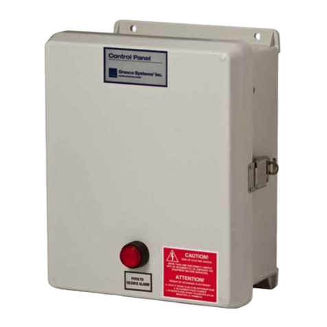
The VCOM-AXA telemetry-enabled panel is used for remote moni-
toringandcontrol of timed, recirculating simplex pumping operations
with gravity discharge.
Basic control logic manages the day-to-day functionality of the
Control Panel. The VCOM-AXA system continuously recirculates,
until the Recirculating Splitter Valve (RSV) seats, then the system
discharges small amounts of treated wastewater throughout the
day. During peak flow conditions, more aggressive timer settings
(overrides) are used to manage the increased demand.
Fault conditions are automatically reported to the VeriComm Mon-
itoring System (a web-based database by Orenco Systems) and
not locally at the panel, making the system virtually invisible to the
homeowner. Alarms and Alerts cause an email to be forwarded to
Anchorage Tank personnel. However, if these conditions are not
respondedto, or thesystemcannotcommunicate with theVeriComm
Monitoring System (the phone line or internet might not be connect-
ed), then the local alarms at the Panel will activate.
To silence local alarms, press the “Push to Silence” button until the
audible alarm stops.
Control Panel Operation
What’s so special about this gray box?

Anchorage Tank II Inc., 2723 Rampart Drive, Anchorage, AK 99501 907-272-3543 anchoragetank.com
Page 8
VCOM AX20-A1 Control Panel Installation Manual
Now that you are finished..... call Anchorage Tank
When the system is complete and the communication line is installed, please give
a call to Anchorage Tank so we can get it registered with both Orenco Systems and
VeriComm, and schedule the System Start-Up with the Service Provider.
Any information you can provide is extremely helpful such as... Home for sale? Home
even built? Anyone living there now? Power turned on/off? Homeowner information
such as name & phone number.And anything else that might help the transition.
272-3543
Other AdvanteX Control Panel manuals
