Westco 16-25 User manual

Street Address: 1360 N. Olive Street Ventura, CA93001 |Mailing Address: P.O.Box 66 Oak View, CA 93022
PRODUCT MANUAL
MODEL 16-25
CASING TONG
MANUFACTURED IN THE USA
SPECIFICATIONS
MAINTENANCE
OPERATIONS
ASSEMBLY
805-648-5004
805-648-5018
CONTACT:
www.westcointl.com
REV: 1 Date:07/23/2019

WARNING: The equipment described in this manual is a
powerful hydro-mechanical tool with exposed rotating
components.
To avoid serious bodily injury to operating and adjacent
personnel and mechanics, the warnings noted on the equipment and in this manual must be
read, understood and followed.
Contents
Page
1.1
Section 1 General Description
Functions 1.2
Specifications 1.5
Options and Accessories 1.6
Section 2 Installation 2.1
Equipment Considerations 2.1
Hanging the Tong 2.2
Connecting the Hydraulic Lines 2.2
Section 3 Operation 3.1
Operating Controls and Indicators 3.1
Preoperating Checks 3.1
Operational Checkout 3.2
Initial Operations 3.3
Positioning Tong and Enclosing Casing 3.3
Operating the Tong 3.3
Maintenance 4.1
Section 4 Daily Inspection 4.2
Monthly Maintenance 4.2
Lubrication 4.2
Tests and Adjustments 4.3
Storage 4.5

Section 5
Section 6
Section 7
Section 8
Contents(continued)
Troubleshooting, Repair and Overhaul
Troubleshooting
Repair
Overhaul
Testing Test Recommendations
Free Run Test
Torque-Up Test
Jaw Installation and Parts
Installation
Jaw Roller Size Check
Tong Assembly, Disassembly and Parts
Disassembly
Rotary Assembly
Parts List for Rotary Assembly
Parts List for Case/Door Assembly
Installation Drawing, Case/Door Assembly
Parts List for Case/Door Assembly
(For Tongs with Half Rollers)
Installation Drawing, Case/Door Assembly
(For Tongs with Half Rollers)
Parts List for Gear Box Assembly
Installation Drawing, Gear Box Assembly
Parts List for Motor Assembly
Installation Drawing, Motor
Parts List for Manifold Assembly
Installation Drawing, Manifold
Parts List for Manifold Assembly
(For Tongs with Tandem Motors)
Installation Drawing, Manifold
(For Tongs with Tandem Motors)
Page
5.1
5.1
5.1
5.3
6.1
6.1
6.1
6.1
7.1
7.1
7.1
8.1
8.1
8.1
8.4
8.5
8.6
8.7
8.8
8.9
8.10
8.11
8.11
8.12
8.13
8.14
8.15

Section 1 General Description
This manual describes the function, installation, operation
and maintenance of the Westco Model 16 hydraulic power
tong. In this section, the functions of the tong, system
specifications, and options and accessories are described.
Figure 1-1: Functional elements of the Model 16 tong
Section 1 Page 1

Functions
The Westco Model 16 casing tong is a hydraulic motor-driven tong capable of running pipe or casing from 2-3/8 to 16
inches in diameter. With a 32 inch (813mm) handle, the tong can produce up to 25,000 lb.ft. (33,895 Nm) in low gear
forward or reverse operation.
An exclusive latch-around (gated), positive-lock jaw system provides sure pipe grip, dynamic balance and safety for
personnel and equipment.
The casing tong incorporates a single or tandemgear-type, fixed-displacement, hydraulic motor to provide drive power
through a gear box and power train. The heart of the unit is a jaw-closing system that forces the jaws together and rotates
them by means of a cam-type rotary gear. The rotary gear is driven by the tow-speed gear train.
In operation, the tong is suspended over the wellbore on a cable. A backup line restrains the tong from moving around
the pipe as torque is applied.
Figure 1-2: Schematic diagram of hydraulic system
Hydraulic Drive System
Figure 1-2 is a schematic drawing of the hydraulic drive system. Hydraulic pressure
from a separate power unit is applied through the hose connectors. To prevent cross-
connection of the hoses, the pressure hose is designed to mate with a 1 inch connector
and the return hose with a 1-1/4 inch connector.
The throttle handle controls the throttle valve for the unit. Pushing the handle applies
pressure to drive the motor forward (for make-up operation) and pulling the handle
applies pressure in a reverse direction (for breakout operation). While the handle is in a
neutral position, fluid circulates freely through the valve and back to the return line.
The hydraulic motor and other hydraulic components are mounted on the tong case
top plate.
________________________________________
Gear Train and Clutch Closure and rotation of the pipe-gripping jaws is accomplished bya large rotary gear.
Mechanical power is transmitted from the hydraulic motor to turn the rotarygear in
either direction.

Section 1 Page 2
The rotary gear assembly is a large-diameter gear that has been segmented into
three sections with pivotal hinges and a latching mechanism. The assembly is
shown in Figure 1-3. The smaller rotary gear segments pivot open to encircle the
pipe being worked and then close and latch while working the pipe. The internal
diameter of the gear has a cam insert surface for actuating the jaws.
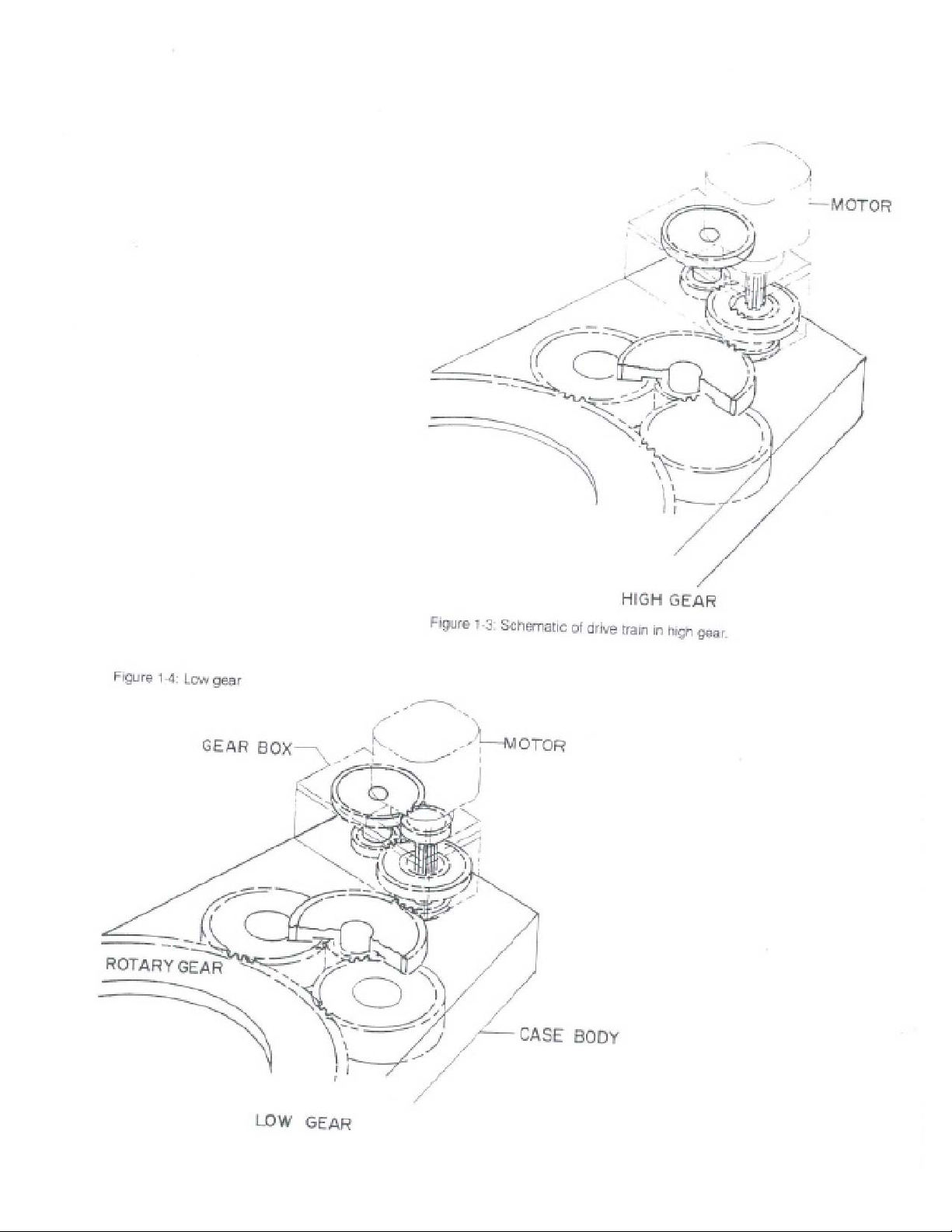
The complete tong gear train is shown in Figure 1-4. The gear train consists of a
shiftable two-speed gear box in a separate housing mounted on the tong top plate.
The hydraulic motor drives a pinion directly through the high (1:1) or low (1:4.3) ratio
of the gear box. The gear box output drives a pinion within the tong case. Through a
cluster gear the input pinion drives a pair of rotary idlers which in turn drive the
rotary gear.
.
Jaw System
Shifting from high to low gear ratios is accomplished by lowering the shift lever
handle.
The model 16 tong uses a three-jaw systemconsisting of two fixed jaws mounted on
the major segment. The jaws are rotated and actuated by the combined action of the
rotary gear, permanent magnets and reversing pin.
During make-up operations, the pipe to be turned is first enclosed in the tong and
the rotary door is closed and latched. Then, with the reversing pin in the make-up
position (as described later), the operator pushes the control lever forward to cause
the jaws to bite and rotate the pipe. To release the jaws and back off fromthe pipe,
the operator pulls the tong control lever outward.
During breakout operations, the reversing pin is placed in the breakout position so
that the jaw bite in the reverse direction. Then the operator pulls the tong control
lever to cause the jaws to bite and break out the pipe. Finally, he pushes the lever
forward to release the jaws and back them off the pipe.
As illustrated in Figure 1-5, the jaw-biting action is a function of the rotary gear
cam. When the rotary gear rotates, the jaw rollers roll up onto the cam surface and force
the jaws to pipe the pipe. Further rotation turns the pipe to make up or break out the
joint.
To provide the restraint necessary for camming to occur, permanent magnets are
added to the jaws. The drag induced by the magnets on a plate within the case body
is sufficient to permit the jaw roller to push the master jaw into engagement with
the pipe. Once the master jaw is engaged, the magnetic drag is overcome,
allowing the jaws to rotate with the rotary gear.
Section1 Page3

Figure 1-3: Schematic of drive train in high gear
Figure 1-4: Low gear

Hydraulic Power Source
Section 1 Page 4
Specifications
The Model 16 tong is designed to be powered by a hydraulic power source
capable of delivering 2,400 psi (175 bar) and 30 gpm (113.6 lpm) for high-
torque, low-speed operation.
For high-speed operation the power source should develop 70 gpm (227.1
lpm) at pressure up to 1,000 psi (69 bar). A load-responsive power source
should be used for optimum results.
Note that the pressure output (psi) of the power source is related directly to
the maximum torque output of the tong. The power source flow output (gpm) is
directly related to the output speed of the tong.
Figure 1-6: Westco casing Tong Specifications
Section 1 Page 5

Power Tong The part numbers and performance specifications for the Model 16 tong are
listed in Figure 1-6. Figure 1-7 is a typical performance curve for the tong.
Figure 1-7: Typical performance curve
Spring Hanger
Lift Cylinder and Controls
Torque Gauge Assembly
16 Inch Rotary Gear
Accessories and Options
The optional spring hanger (part no. 100181-001) (Figure 2-3) permits the tong to
move up or down to allow for thread length change in make-up and breakout
operations. When used, the spring hanger should be attached directly to and used
as a hanger for the tong.
The hydraulic lift cylinder assembly (partno. 103652-001) provides a means for
raising and lowering the tong during operations. When a cylinder is ordered with a tong,
the tong contains an additional control lever for controlling the lift cylinder up or down.
This lever is identical to the tong operating control lever. Pulling the lever outward
provides pressure fromthe hydraulic power unit to operate the lift cylinder upward
and thus to raise the tong, whereas pushing the controllever forward operates the cylinder
downward to lower the tong. The central lever position is the neutral position.
The optional torque gauge assembly part no. 111918-001 for 0 to 30,000 lbs. ft
(40,675 Nm); 111918-002 for 0 to 20,000 lbs. ft (27.116Nm) measures the torque
exerted while the tong is used in make-up or breakout operations. Consisting of a
hydraulic cylinder and torquemeter connected by a pressure hose, the torque gauge
assembly senses and indicates the torque developed during an operation. For
operation, the hydraulic cylinder is connected by a shackle to the rear of the tong. A
backup line is connected to the cylinder and is tied off to a solid part of a rig structure
to form an angle of 90 degrees to yield accurate torque readings. See Figure 2-2
The 16 inch rotary gear (part no. 112373-001) is required for working casing
larger than 13-3/8 inches in outside diameter.

Section 1 Page 6
Section 2 Installation
The Tong
Equipment Considerations
Replace the jaws that are on the tong with the correct-sized jaws according
to the size of pipe being used. Refer to "Jaw Installation and parts" (Section 7)
for available jaw sizes and installation procedures.
WARNING: Do not attempt to change jaws with power unit in operation.
Failure to observe proper precautions could result in serious injury.
Figure 2-1: Tong space requirement
Section 2 Page 1

Hanging the Tong
The tong is transported to the well site and hung into position as illustrated in Figure 2-3
and as follows:
Connect cable to the tong bail. The tong should be suspended by a steel cable from a point
high enough on the derrick to assure easy handling and maneuverability. The hang point
should be positioned as near the center of the rotary gear as possible (allowing for hanger
offset from tong opening centerline) without interfering with movement of the casing handling
tools. The line should anchor securely to the rig frame. If a spring hanger is used, extend the line
over a pulley and down to the spring hanger. The tong line should position the tong at the
anticipated average height of the joint during use. This will allow the tong to follow the joint
during make-up or breakout.
WARNING: To prevent bodily injury this steel cable must be rated for 4,000 lbs
(1814.4 kg) minimum working load.
If no spring hanger is used, use two pulleys to keep the counterbalance, which weighs
approximately 1,200 pounds (544.3 kg), out of the operating area.
The tong must be as near level as practicable for proper operation. When the tong is being
leveled, the jaws should have been inserted and the doors closed. For fore and aft leveling,
adjust the bolts at the hanger joint on each side of the case, assuring both bolts are in contact
with the hanger strut. For side-to-side leveling, move the clevis in the notched insert at the top
of the hanger to the required position.
Connect the backup line to the torque gauge to restrain tong rotation and to provide torque
readings for operations.
WARNING: To prevent serious bodily injury secure tong to derrick with a backup line
rated to 25,000 pounds (11340 kg) minimum working load.
If no torque gauge is used, connect the line directly to the backup line bracket.
Secure the other end of the backup line to a solid part of the rig to form a 90 degree angle
with the tong centerline. Failure to maintain the 90 degree angle will result in torque
measurement errors.
Connecting the Hydraulic Lines
Hook up the pressure hose to the one-inch fitting on the tong by forcing the connectors
together while turning the fitting. Hook up the return hose from the power unit to the 1-1/4
inch connector on the tong in the same manner.
WARNING: Be sure connectors are completely tight.
If a lift cylinder is used, connect the hose from the lift cylinder to the connector provided
on the tong.
Start the power unit and allow hydraulic fluid to circulate through the tong until fluid
reaches operating temperature.
NOTE: This period will vary according to the ambient temperature. In severe weather
conditions you may need to operate the systemfor several minutes before using
the tong. In warm climates a brief warm-up period is adequate.
While the system warms up, check the connections to be sure that no leaks occur.
Retighten connections if leaking.
NOTE: Refer to Figure 4-3 in "Maintenance" for recommended hydraulic fluid.
WARNING: When replacing hydraulic hoses, piping and fittings, be sure
replacement components are rated at no less than 3,000 psi (206.8 bar)
working pressure and 10,000 psi (689.5 bar) burst pressure.

Section 2 Page2
Power Before installing the tong for field operations, ensure that an appropriate power unit
is available and that the power unit is adjusted for use with the tong. To operate the
tong within its full capability, the relief valve on the hydraulic power unit should be adjusted
to 2,500 psi and the bypass valve to 900 to 1,000 psi. Refer to the power unit manual for
the procedure on power unit valve adjustments. Normal care should be exercised in
locating the power unit and connecting the tong. Excessive distance between tong and
power source will result in pressure losses.
Figure 2-2: Torque gauge Figure 2-3: Installation of Power Tong
Accessories
The accessories necessary for the type of operation to be performed must
be available.
Torque Gauge Assembly - Once installed, the torque gauge assembly becomes
an integral part of the unit. To install the torque gauge on the tong, proceed
as follows:
1. With mounting screws, mount torque gauge into position on torque
Gauge plate (Figure 2-2).
2. Route hose to avoid interference with tong operation.
3. Secure one side of load cell to backup line bracket on rear of tong.
Lift Cylinder - If the system is not counterbalanced, a lift cylinder should
be used. For lift cylinder operation, the tong must be equipped with an additional
valve section. The lift cylinder should be suspended from the line that will hang the
tong, as shown in Figure 2-3.
Spring Hanger - A typical spring hanger installation is shown in Figure 2-3.
For a counterbalanced support line, the spring mount is suspended from the line.
When a lift cylinder is used, the spring mount may be installed above or below
the lift cylinder as shown in Figure 2-3.
Section 2 Page 3

Section 3 Operation
Operating Controls and Indicators
Before operating the unit, the operator should become thoroughly familiar with
the operating controls and gauges. Then, before initial operation and daily thereafter,
he should make the recommended adjustments and operational checks,
Figure 3-1 illustrates the operating controls and gauges. Functions of the controls
and gauges are described in Figure 3-2.
Figure 3-1: Tong controls Preoperating Checks
After installing the system, check to be sure that all necessary adjustments are
made and that the system is functioning correctly.
Before attempting operation, verify that operating personnel understand proper
operation of the tong and the safety requirements. Ensure that all lines and
equipment associated with hanging and securing the tong are of adequate size and
good condition.
The power unit output pressure must be properly adjusted. Refer to the
instruction manual on the power unit and perform the output pressure adjustment
procedure for the required pressure.

Section 3 Page 1
Operational Checkout
Before starting a new job, perform the following operations and be sure the tong
operates correctly.
Place the reversing pin in the hole on the rotary next to "make."
NOTE: For tandem motor tongs, also place the motor selector valve in high speed mode.
Move the shifting lever to the high-speed position (up). Push the throttle handle
Forward and verify that the jaws bite and the rotary turns at high speed.
NOTE: Rotary should move 6 inches (152.4 mm) before jaws grip the pipe and torque
builds up. If torque is applied before the rotary plunger (Figure 4-1) is out of the
pocket, rotary lockup and subsequent case damage may occur.
Pull the throttle handle to neutral and move the shifting lever to the low-speed position
(down). Again push the throttle handle and verify that the jaws bite and the rotary
turns at low speed.
Return the throttle handle to neutral position.
Use the throttle handle to operate the tong so that the rotary gear is aligned with
the doors.
Place the reversing pin in the hole on the rotary next to "break." Repeat the
checkout procedure to check breakout operation.
If the lift cylinder is installed, pull the lift cylinder control lever back and verify
that the cylinder operates to lift the tong. Then push the lift cylinder control lever
forward and verify that the cylinder operates to lower the tong.

Section 3 Page 2
Initial Operations
After the tong is transported to the job site, hoisted into operating position, and the backup
line attached, leveled and connected with power unit as described in the installation section,
proceed as follows:
1. Be sure shifting lever and throttle handle are in neutral position.
2. Start hydraulic power unit.
3. Perform an operational check and make any required adjustments before continuing.
4. Place reversing pin in the make-up hole for make-up operation or in the breakout hole
for breakout operation. (See Figure 3-3)
Figure 3-3: Reversing pin
Positioning Tong and Enclosing Casing
After performing the initial operations, position the tong for the make-up or breakout work to be done.
Position the tong at the proper height for gripping casing as follows:
1. If the tong is installed with a counterbalanced system, lift or lower the tong to the
desired position.
2. If a lift cylinder is used, operate the lift cylinder control lever (located to the right of tong
control lever) to position the tong.
Place the tong on the casing section positioned for make-up or breakout. Close the doors.
Then operate the tong as follows: Operating the Tong
WARNING: Be sure no part of the body or clothing is in tong rotary area and no cables or
Equipment other than casing are enclosed in the tong. Operator and all other
Objects must be clear of backup line and traveling path of tong while in operation.
Initially select high-speed operation by movingthe shifting lever up and the motor selector
to the right.
To begin turning the casing clockwise for make-up operation, push the throttle handle forward.
To begin turning the casing counterclockwise for breakout operation, pull the throttle handle back.
CAUTION: Initial gripping action must not occur while plunger is in the cam pocket:
damage to the tong may result. If gripping occurs immediately upon initiation
of rotary motor (before the plunger is depressed) check jaw roller for proper
size (Section 7, p.1) and/or rotate in opposite direction before gripping so that
plunger is in depressed position before gripping occurs.
Once the tong stalls out, release the throttle handle and move the shifting lever and motor
selector to the low-speed position.
Operate the throttle handle to complete the torquing operation.

Section 3 Page 3
Observe the reading on the torque gauge. When proper torque is obtained, move the
throttle handle in the opposite direction to back off. Center the plunger in pocket, open
doors and pull tong away from joint.
Reposition casing tong away from rotary table as necessary, and repeat the operating
procedures as required for each joint.
After operation, open the doors and push the tong back off the casing.

Section 3 Page 4
Section 4 Maintenance
Servicing the tong consists of inspection, lubrication, tests and adjustments. Should
servicing reveal requirements for repairs, refer to the appropriate procedures in
"Troubleshooting, Repair and Overhaul" and "Testing" (Sections 5 and 6).
Overhaul Equipment
Jaw Dies
Rotary Gear
Latch Hook Springs
Jaw Rollers
Daily Inspection
Figure 4-1 illustrates the points that should be inspected prior to every job and
once every operating day thereafter.
Inspect the unit and its accessories for obvious damage, evidence of hydraulic
leaks, etc. Refer to the overhaul procedures for removal and replacement of
any faulty parts.
Inspect jaw dies to be sure that the biting edge is not worn excessively and is
capable of biting effectively. Change the dies if necessary.
Inspect gear teeth for excessive wear, damage or breakage. Replace if more
than two adjacent teeth are broken. If excessive wear or breakage is found,
inspect all internal gears and grease packing for metal particles and damage.
Springs must exert sufficient force to close latch firmly on the lug. Replace
if necessary.
Inspect jaw roller for free rotation. Lubricate as described under Jaw Roller
Lubrication procedure.

Monthly Maintenance
Once each month make the following checks and take appropriate corrective action:
1. Check rotary gear guide rollers for wear or breakage, and replace if necessary.
2. Check jaw rollers for wear or breakage, and replace if necessary.
3. Check shifting operation, shifting shaft nuts and shifting shaft detent.
operation as described in "Tests and Adjustments" in this section.
4. Inspect the rotary gear and internal gears.
5. Examine the rotary plunger for evidence of wear or breakage.
6. Check the oil level in the gear box.
7. Check the torque gauge cylinder for low fluid volume. Fluid level is low if
½ inch or more of the cylinder rod is exposed when under tension.
8. Check all fasteners for tightness. Lubrication
Proper lubrication is important to the operation and long life of the tong.
Hydraulic Fluid
Requirements
Grease Zerts
During normal operation, the tong should remain charged with hydraulic fluid,
even when the hydraulic hoses are disconnected.
At the beginning of each job and once every operating day thereafter, use a grease
gun to grease the 17 grease zerts. In general, be liberal with grease. Over-greasing
will do no harm, whereas greasing too little can result in excessive wear. Figure
4-2 shows the lubrication points, and Figure 4-3 specifies the types of grease
to be used.
Grease the tong as follows (numbers enclosed in parentheses refer to grease
points identified in Figure 4-2):
1. On top of the top, grease the shifting shaft (19).
*Specifications are listed for average conditions. For applications involving extreme heat or cold, consult
Westco engineering for recommendations. Section 4 Page 2

WARNING: After applying power to turn rotary gear, disable hydraulic
system before proceeding.
2. Grease the three gear bearings.
3. Grease all guide roller bearing zerts (1 through 12; 13 and 14 when present).
4. Pack the rotary plunger and plunger pocket with grease.
Gear Grease To pack the tong with grease, refer to Figure 4-2 and Figure 4-3 and proceed as follows:
WARNING: Packing the gears while the power unit is operating is extremely
dangerous. Failure to observe proper precaution in maintaining this
unit could result in serious injury.
1. Disable the tong by both of the following methods.
WARNING: Keep hands out of the jaw area while the power unit is operating.
Disconnect power from the power unit electrical motor or turn off diesel engine as
applicable, shift speed lever to neutral and set control lever to neutral.
Disconnect the hydraulic pressure line (1 inch line) from the tong at the hose connector.
2. Remove the rotary gear asdescribed in "Tong Disassembly and Parts" (Section 8).
3. Pack the unit with the specified gear grease (see Figure 4-3) by liberally applying
Grease through the back rotary opening in case (Figure 4-2).
Figure 4-4: Door latch Figure 4-5: Guide roller shaft positions
Test and Adjustments
The following tests and adjustments should be made.
Door Latch Adjustment WARNING: The door latch must be readjusted each time the rotary guide
rollers are adjusted.
The latch hinge pin is an eccentric shaft providing adjustment. The high point
of the eccentric is indicated by an arrow. With the rotary in place and six guide
rollers adjusted so that the rotary is centered, rotate the latch hinge pin to
achieve the latch/lug alignment shown in Figure 4-4.
After adjusting the latch hinge pin, install two bolts and lockwashers to retain
adjustment, and tighten the locknut on the bottom of the shaft.
Following adjustment, recheck operation by opening and closing the doors several
times. With the doors closed and latched, pull on either door. The latch must
not release.
WARNING: Failure to adjust properly can result in door opening under
load, damaging the tong and injuring personnel.
Section 4 Page 3

Rotary Centering
Adjustment WARNING: Proper adjustment of the rotary is essential to tong operation and
reliability.
With the rotary removed and referring ti Figure 4-5, loosen locknuts on the shafts at
points 1 through 6 and 9 through 14. Remove the bolts and lockwashers from the shafts.
Position the shafts with the high-point arrow located radially away from the rotary.
If half rollers are installed atpoints 7 and 8, position the high-point arrow radially away
from the rotary. Lock the shaft into this position by tightening the locknut and installing two
bolts and lockwashers.
Install the rotary assembly and close and latch the doors. Then adjust latch pin until
tight on cam and secure shaft in place (to nearest full bolt hole) with bolts and lockwashers.
WARNING: Check for gear mesh. Improper meshing of gears can result in
tooth breakage.
1. Use shafts at position 1,4,11 and 14 to position fully the rotary.
2. Rotate shaft 1 counterclockwise until rotary teeth mesh with idler gears.
3. Rotate shaft 4 counterclockwise ¼ turn and then rotate shaft 11 clockwise ¼ turn.
Repeat adjustment on shafts 4 and 11 until rotary is snug and positions of high point
arrows on these shafts are in approximately the same position in relation to the
case opening.
4. Rotate shaft 1 counterclockwise and shaft 14 clockwise simultaneously until rotary
is snug and positions of high point arrows on these shafts are in approximately the
same position in relation to the tong opening.
5. Rotate shafts 2,3,5 and 6 counterclockwise until cams on shafts make their guide
rollers lightly touch rotary.
6. Rotate shafts 9, 10, 11, 12 and 13 clockwise until cams on these shafts make their
guide rollers slightly touch rotary.
7. When the guide rollers are snugged up, the high point arrow should be in approximately
the same position in relation to the case opening. Readjust to obtain this
relationship if necessary.
8. Secure case shafts as follows:
If any two holes in the shaft shoulders align with tapped holes in top plate for shafts
4, 5, 6, 9, 10 and 11. rotate shafts 4, 5 and 6 clockwise and rotate shafts 9, 10 and 11
counterclockwise ¼ to ½ shaft shoulder hole. At this point, two opposing shaft
shoulder holes should align with two tapped holes in the top plate. (A sharp object
is required to align shaft shoulder holes with two of the four tapped holes in the top
plate for each shaft).
If the shaft shoulder holes are not in full alignment with two opposing tapped holes in
the top plate, rotate shafts 4, 5 and 6 clockwise and rotate shafts 9, 10 and 11
counterclockwise ¼ to ½ shaft shoulder hole. Pierce the guide roller shaft gasket with
a sharp object to locate two opposing shaft shoulder holes which are in full
alignment with two of the four tapped holes in the top plate.
After adjustment, secure shafts 4, 5, 6, 9, 10 and 11 with bolts and lockwashers.
9. Secure door shafts as follows:
For those tongs with tandem2 inch hydraulic motors, follow procedures in
paragraph 8, adjusting shafts 1, 2 and 3 clockwise and shafts 12, 13 and 14
counterclockwise.
For tongs with other motors, use procedures similar to paragraph 8, but adjust
½ to full hole (rather than ¼ to ½ hole). Adjust shafts 1, 2 and 3 clockwise while
adjusting shafts 12, 13 and 14 counterclockwise. After adjustment, secure shafts
1, 2, 3, 12, 13 and 14 with bolts and lockwashers.
10. Loosen door latch shaft and adjust according to door latch adjustment procedure.
WARNING: Bolts prevent loss of adjustments and carry no tension loads. Over-
torquing of locknuts or bolts prevents free guide roller rotation.
Section 4 Page 4
Table of contents
Other Westco Industrial Equipment manuals