EnglishDeutsch
 logo
Brands
  1. Home
  2. •
  3. Brands
  4. •
  5. Parker
  6. •
  7. Industrial Equipment
  8. •
  9. Parker Racor RK11-1721 User manual

Parker Racor RK11-1721 User manual

This manual suits for next models

3

Other Parker Industrial Equipment manuals

Parker Siemens APOGEE P1 User manual

Parker

Parker Siemens APOGEE P1 User manual

Parker Helac PowerTilt Series Installation and operating manual

Parker

Parker Helac PowerTilt Series Installation and operating manual

Parker SCFT 02-02 Series User manual

Parker

Parker SCFT 02-02 Series User manual

Parker Bestobell Valves IOM 002 User manual

Parker

Parker Bestobell Valves IOM 002 User manual

Parker AC20 Series User manual

Parker

Parker AC20 Series User manual

Parker Series V14 Guide

Parker

Parker Series V14 Guide

Parker ETH080 User manual

Parker

Parker ETH080 User manual

Parker MSG17-4830-UM User manual

Parker

Parker MSG17-4830-UM User manual

Parker Aries AR-01xR User manual

Parker

Parker Aries AR-01xR User manual

Parker KarryFlare User manual

Parker

Parker KarryFlare User manual

Parker IQAN-LC5-C0 Series User manual

Parker

Parker IQAN-LC5-C0 Series User manual

Parker Gemini GV6K Series Manual

Parker

Parker Gemini GV6K Series Manual

Parker LX80L User manual

Parker

Parker LX80L User manual

Parker OLAER IBV Series Setup guide

Parker

Parker OLAER IBV Series Setup guide

Parker PHK User manual

Parker

Parker PHK User manual

Parker SC80 User manual

Parker

Parker SC80 User manual

Parker HTG Series Manual

Parker

Parker HTG Series Manual

Parker ParflangeF37 User manual

Parker

Parker ParflangeF37 User manual

Parker AC20 Series User manual

Parker

Parker AC20 Series User manual

Parker AC20 Series User manual

Parker

Parker AC20 Series User manual

Parker D-Pak Manual

Parker

Parker D-Pak Manual

Parker Finite JDK5000V Installation guide

Parker

Parker Finite JDK5000V Installation guide

Parker Parflange ECO 25 User manual

Parker

Parker Parflange ECO 25 User manual

Parker HTR Series Datasheet

Parker

Parker HTR Series Datasheet

Popular Industrial Equipment manuals by other brands

ABB Unifix AD Instruction handbook

ABB

ABB Unifix AD Instruction handbook

Mark 7 Evolution user manual

Mark 7

Mark 7 Evolution user manual

Husky HyPET Original instructions

Husky

Husky HyPET Original instructions

bora PM-1800 user manual

bora

bora PM-1800 user manual

Grizzly T32428 owner's manual

Grizzly

Grizzly T32428 owner's manual

Siemens 8MF1 Series operating instructions

Siemens

Siemens 8MF1 Series operating instructions

ABB HT610965 Operation manual

ABB

ABB HT610965 Operation manual

ABB SafeLink Installation and operating instructions

ABB

ABB SafeLink Installation and operating instructions

Phoenix PHX-150 user guide

Phoenix

Phoenix PHX-150 user guide

ABB A165-L32 Operation manual

ABB

ABB A165-L32 Operation manual

ABB HT842936 Operation manual

ABB

ABB HT842936 Operation manual

Hermetica 10 Series user manual

Hermetica

Hermetica 10 Series user manual

HORNER OEE Solution manual

HORNER

HORNER OEE Solution manual

Hammerhead HG375 parts manual

Hammerhead

Hammerhead HG375 parts manual

SCHUNK VERO-S NSE-A3 138 Assembly and operating manual

SCHUNK

SCHUNK VERO-S NSE-A3 138 Assembly and operating manual

ABB HT566657 Operation manual

ABB

ABB HT566657 Operation manual

Webasto GSE CAN installation guide

Webasto

Webasto GSE CAN installation guide

ABB HT614003 Operation manual

ABB

ABB HT614003 Operation manual

https://manuals.online logo
https://manuals.online logoBrands
  • About & Mission
  • Contact us
  • Privacy Policy
  • Terms and Conditions

Copyright 2026 Manuals.Online. All Rights Reserved.

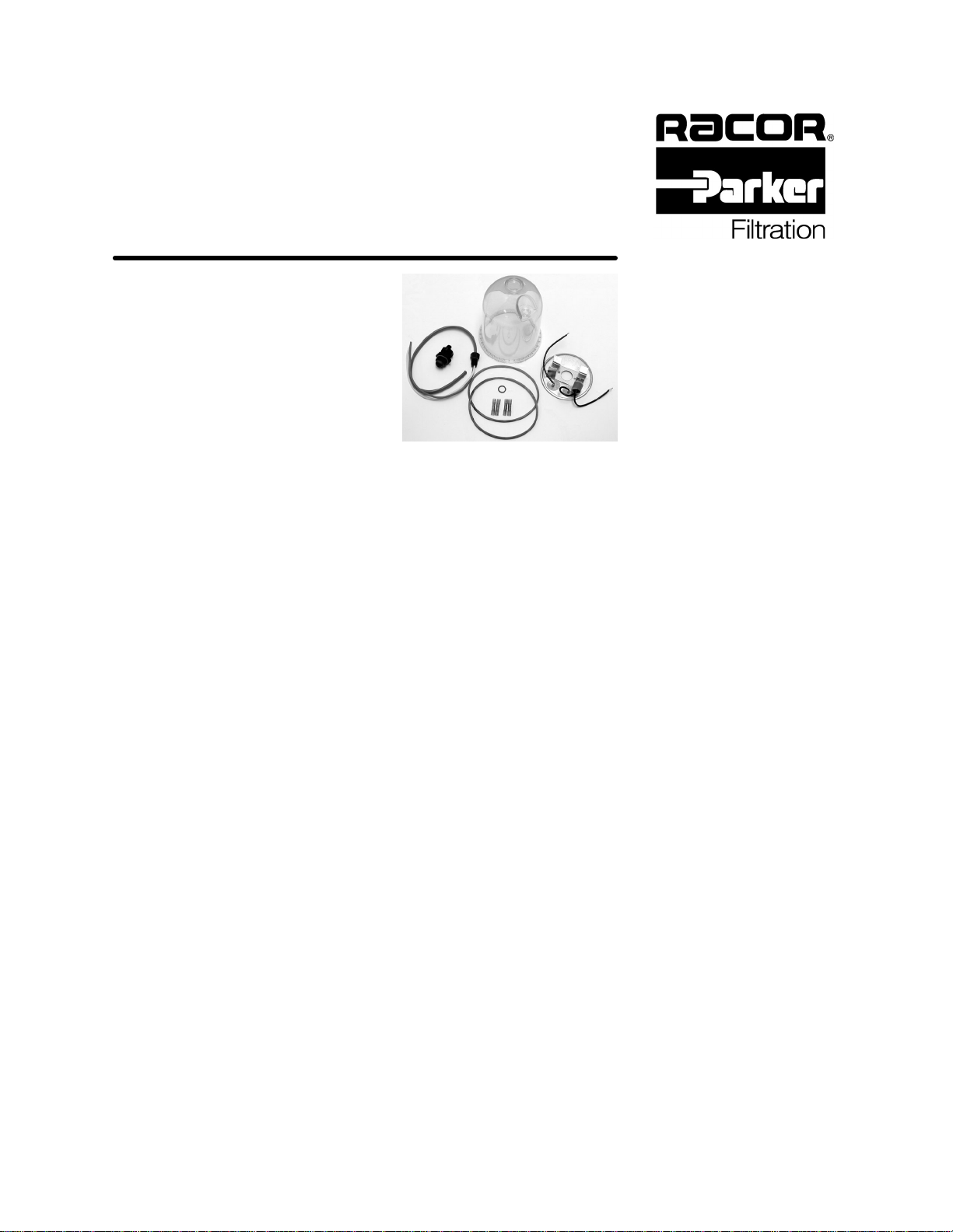
Feedthru Heater & Bowl Kit
Installation Instructions
For kit numbers: RK11--1721 (150 watt, 12 volt)
RK11--1721--01 (150 watt, 24 volt)
RK11--1721--02 (300 watt, 12 volt)
RK11--1721--03 (300 watt, 24 volt)
Tools Needed
SShop towels
SCollection pan
SWire Cutter/Crimper
S5/8” wrench
S3/8” wrench
SHeat Gun or Hair Dryer
SMotor oil or Diesel Fuel
Installation Time
S1 hour (average)
Installation Instructions
First become familiar with the illustration on the back of this page.
1. Remove the ground cable from the battery as a safety measure.
2. With a collection pan in place, drain the filter unit using the self--venting drain on the bottom of the bowl.
3. Remove the T--handle and lid on the filter assembly.
4. Remove and discard the O--ring on the T--handle and the gasket for the lid. Take caution to avoid
scratching the smooth sealing surfaces.
5. Remove and properly dispose of the element.
6. Using a 3/8” wrench, remove the four (4) bolts that hold the bowl ring to the filter housing base.
7. Pullthebowlringand bowl offthehousinganddiscard the O--ring thatgoesbetween the bowl and base.
8. Withthefilterelementremoved,slidetheheater,withthethermostat(s)facingdown,overthecentertube
ofthefilter. For150watt models,theheaterwill restatthebaseofthecentertubeandtheheater bracket
will keep the heater from turning. For the 300 watt models, the heater will rest on the filter base and the
thermostat(s) will keep the heater from turning.
9. Pull the heater lead wires through the filter base and set aside.
10. Usea5/8”wrenchtothreadtheheaterfeedthruassembly(theyellowandredwirewiththemoldedplastic
plug) through the bowl as shown in the picture on the back of this page. Make sure the plug is tightened
snugly (10 inch pounds).
11. Strip off about 1/4” of insulation from the yellow and red wires.
12. ForkitsotherthanRK11--1721--02(300watt,12volt),crimpaspliceconnectortotheredandyellowwires.
Note: the 300 watt 12 volt heater already has the splice connectors attached to the heater lead, so it is
not necessary to attach them to the red and yellow wires (they are used later).
13. Slide one of the two 5” diameter gaskets over the red and yellow wires.
14. Crimptheyellow wiretoeitheroneoftheheaterwiresprotrudingthrough thebowlandcrimpthe red wire
to the remaining heater wire (the heaters are designed to run on either polarity).
15. Use a heat gun or a hair dryer to shrink fit the splice connectors. Once heated, the connectors will seal
the crimp.
16. Apply lubricant (motor oil or diesel fuel) to the bowl gasket.
17. Re--attach the bowl to the base with the bowl ring and the 3/8” bolts that were removed earlier. Tuck the
remaining lengths of wire into the bowl as you attach it to the base. Tighten the bolts snugly (55 to 65
inch pounds).
Parker Hannifin Corporation
Racor Division
PO Box 3208, 3400 Finch Rd.
Modesto, CA 95353 USA
209--521--7860/800--344--3286
www.parker.com/racor
e--mail: racor@parker.com
Kit number RK11--1721
18. Install a new filter element into the filter housing and fill housing with clean fuel.
19. Lubricate the remaining 5” gasket and install it in the grove on the lid.
20. Lubricate the T--handle O--ring and install in onto the T--handle.
21. Re--attach the lid and T--handle to the filter housing. Tighten the T--handle snugly by hand only -- do not
overtighten.
22. Strip back enough of the gray insulation from the heater wire to attach the remaining two (2) splice
connectorstotheendoftheyellow and red wires. The yellow wireshould be attached to ground andthe
redtohot. Ifdesired,theredwirecouldbeconnectedtoanignitionactivatedrelaytocontroltheoperation
of the heater, otherwise, the thermostat settings on the heater will control heater operation.
23. Re--attach the battery cable that was removed earlier.
24. Start engine and check for leaks. Correct as necessary.
If you have any questions or problems with the installation of this heater kit, contact your Racor distributor
or call Racor Technical Support at 1--800--344--3286 extension 7555, Monday to Friday, 6 AM to 5 PM, PT.
Component List
1. Filter Housing
2. Filter Element
3. T--handle
4. T--handle O--ring
5. Lid
6. Lid or Bowl Gasket
7. Heater
8. Heater Leads
9. Thermostat(s)
10. Return Tube
11. Heater Feedthru Assembly
12. Splice Connector
13. Bowl
14. Bowl Ring
15. Housing Base
16. Bolt (4)
Ignition Activated Control Schematic
Racor’s policy is one of continual improvement in design and manufacturing to insure still finer products; therefore,
specifications, equipment and product information, while correct at the time of publication, is subject to change without
notice. Copyright, Parker Hannifin Corporation, December 2000. Part Number 11--1766, Rev. A
3
5
10
1
7
9
16
13
4
6
14
2
6
8
12
15
11
Fuse
block
Ignition
switch
Battery +
--
C4 B2
A5 E3
Relay
1amp
fuse
*fuse
*resistor
Manual on--off
switch (optional)
*Use resistor and 15 amp fuse with 24 vdc systems.
From
Filter
Racor Relay
(not provided)
RK11861 -- 12 vdc
(upto300watts)
RK11862 -- 24 vdc
(upto360watts)
Red
Yellow