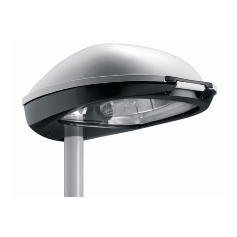
AEC ILLUMINAZIONE BASE BA/1 User manual

rev. 07/07/2021 Pag. 1 of 15
Mounting Instructions
Techinical Division
BASE BA/1 & BASE BA/2
Made in Italy
ISTRUZIONI DI MONTAGGIO PER: BASE BA/1 & BASE BA/1
MOUNTING INSTRUCTIONS FOR: BASE BA/1 & BASE BA/1
Le seguenti istruzioni illustrano il montaggio delle basette BASE BA/1 e BASE BA/2, valide per la seguente lista
di pali:
The following instructions show the mounting of the cover base BASE BA/1 e BASE BA/2. These instructions
are valid for the following list of poles:
BASE BA/1
➔PM (Ø102-Ø114) - DS –EC (Ø 102) –PU –PL (Ø 102)
BASE BA/2
➔PM (Ø127) –PK (Ø127) –PN –PA –PL (Ø127) –PS –PZ (Ø127) –PE (Ø127) –PH (Ø127) –PB (Ø127)
DISEGNI DIMENSIONALI - DIMENSIONAL DRAWINGS
Quote in mm –Dimensions in mm
Ø [mm]
102-114
BASE BA/1
127
BASE BA/2

rev. 07/07/2021 Pag. 2 of 15
Mounting Instructions
Techinical Division
BASE BA/1 & BASE BA/2
Made in Italy
PIASTRA - PLATE
i
LxL
Ø Foro
Hole Ø
Spessore
Thickness
180
250x250
22
15
260
350x350
30
20
KIT TIRAFONDI –ANCHOR BOLTS
i
LxL
L
500
700
Ø
M 18
M 27

rev. 07/07/2021 Pag. 3 of 15
Mounting Instructions
Techinical Division
BASE BA/1 & BASE BA/2
Made in Italy
INDICE –INDEX
MONTAGGIO: Base BA/1 (per pali con piastra) .....................................................................................4
MOUNTING: BA/1 Base Cover (for poles with plate)..............................................................................4
MONTAGGIO: Base BA/1 (per pali interrati)...........................................................................................7
MOUNTING: BA/1 Base Cover (for in-ground poles)..............................................................................7
MONTAGGIO: Base BA/2 (per pali con piastra 250mm x 250mm).........................................................9
MOUNTING: BA/2 Base Cover (for poles with 250mm x 250mm plate)..................................................9
MONTAGGIO: Base BA/2 (per pali con piastra 350mm x 350mm).......................................................11
MOUNTING: BA/2 Base Cover (for poles with 350mm x 350mm plate)................................................11
MONTAGGIO: Base BA/2 (per pali interrati).........................................................................................14
MOUNTING: BA/2 Base Cover (for in-ground poles)............................................................................14

rev. 07/07/2021 Pag. 4 of 15
Mounting Instructions
Techinical Division
BASE BA/1 & BASE BA/2
Made in Italy
MONTAGGIO: Base BA/1 (per pali con piastra)
MOUNTING: BA/1 Base Cover (for poles with plate)
Piastra ≥ 250mm x 250mm e palo Ø102mm- Ø114mm
≥ 250mm x 250mm Plate and Ø102mm- Ø114mm Poles diameter
1. Seguire le indicazioni della direzione lavori per il posizionamento dei tirafondi. I tirafondi devono uscire
dal terreno per 70 mm (Immagine a).
Follow the statements of the work directioner for the positioning of the anchor bolts. The anchor bolts
must protrude from the ground by 70 mm (Pic. a).
2. Stringere fino all’altezza desiderata i dadi (sotto la piastra) nei rispettivi tirafondi filettati.
Tighten the bolts (under the plate) to the desired height in the respective anchor bolts.
3. Inserire il palo con relativa piastra saldata ed inserire i dadi sui tirafondi, sopra la piastra.
Insert the pole with its welded plate and insert the bolts (over the plate) on the anchor bolts
4. Sistemare il palo con piastra in posizione e regolare la sua inclinazione agendo sui dadi di regolazione
(sotto la piastra) fino a raggiungere la posizione corretta.
Place the pole with the plate in position and adjust its inclination by acting on the adjustment bolts (under
the plate) until it reaches the correct position.
5. Stringere ai tiranti le rondelle e i dadi. Il palo risulta bloccato in posizione
Tighten the washers and bolts to the anchor bolts. The pole is locked in position
Tirafondi filettati (x4)
Anchor bolts (x4)
Sotto la piastra –Under the plate
Dadi Mxx e rondelle Øxx mm (x4)
Bolts Mxx and washers Øxx mm (x4)
Sopra la piastra –Over the plate
Dadi Mxx e rondelle Øxx mm (x4)
Bolts Mxx and washers Øxx mm (x4)
Piastra - Plate
Piastra sottobase –Sub-base plate
a
Filo superiore del tirafondo
Upper thread of the anchor bolt

rev. 07/07/2021 Pag. 5 of 15
Mounting Instructions
Techinical Division
BASE BA/1 & BASE BA/2
Made in Italy
6. Riempire lo spazio al di sotto della basetta (70 mm di altezza) mediante materiale di riempimento
espansivo idoneo (Immagine b). Avere cura di coprire piastre e tirafondi (Immagine b).
Fill the the junction zone under the plate (70 mm high) with appropriate expansive additive (Pic. b).
Take care to cover plates and anchor bolts (Pic. b).
7. Una volta che il palo è in posizione e che il getto di materiale di riempimento è stato posato, fissare la
piastra sottobase al getto mediante 4 fori Ø14 mm.
Once the pole is placed and the filling material jet has been laid, fix the sub-base plate to the concrete by
means of four Ø14 mm holes.
b
Riempire con adeguato materiale di
riempimento espansivo
Fill with appropriate expensive additive
material
Piastra sottobase –Sub-base plate

rev. 07/07/2021 Pag. 6 of 15
Mounting Instructions
Techinical Division
BASE BA/1 & BASE BA/2
Made in Italy
8. Calare la basetta BA/1 e fissarla alla sottobase mediante viteria a brugola M5 x 12 mm, coppia di
serraggio 5 Nm (Immagine c).
Lower the BA/1 base cover and fix it to the sub-base by means of Allen screws M5 x 12 mm, screwing
torque of 5Nm (Pic. c).
c
Basetta BA/1 –BA/1 Base cover
Viteria a brugola M5x12 mm; 5Nm (x4)
Allen Screw M5x12 mm; 5Nm (x4)

rev. 07/07/2021 Pag. 7 of 15
Mounting Instructions
Techinical Division
BASE BA/1 & BASE BA/2
Made in Italy
MONTAGGIO: Base BA/1 (per pali interrati)
MOUNTING: BA/1 Base Cover (for in-ground poles)
Palo Ø102mm- Ø114mm
Ø102mm- Ø114mm Poles diameter
1. Posizionare il palo con interramento, seguendo le istruzioni della direzione lavori
Place the in-ground pole, following the instructions of the direction works.
2. Una volta che il palo è in posizione, fissare la piastra sottobase al getto mediante 4 fori Ø14 mm
(Immagine A).
Once the pole is in place, attach the sub-base plate to the concrete by means of four Ø14 mm holes (Pic.
A).
a

rev. 07/07/2021 Pag. 8 of 15
Mounting Instructions
Techinical Division
BASE BA/1 & BASE BA/2
Made in Italy
3. Calare la basetta BA/1 e fissarla alla sottobase mediante viteria a brugola M5 x 12 mm, coppia di
serraggio 5 Nm (Immagine b).
Lower the BA/1 base cover and fix it to the sub-base by means of Allen screws M5 x 12 mm, screwing
torque of 5Nm (Pic. b).
b
Viteria a brugola M5x12 mm; 5Nm (x4)
Allen Screw M5x12 mm; 5Nm (x4)

rev. 07/07/2021 Pag. 9 of 15
Mounting Instructions
Techinical Division
BASE BA/1 & BASE BA/2
Made in Italy
MONTAGGIO: Base BA/2 (per pali con piastra 250mm x 250mm)
MOUNTING: BA/2 Base Cover (for poles with 250mm x 250mm plate)
Piastra 250mm x 250mm e palo Ø127mm
250mm x 250mm Plate and Ø127mm Poles diameter
1. Seguire le indicazioni della direzione lavori per il posizionamento dei tirafondi. (Immagine a).
Follow the statements of the work directioner for the positioning of the anchor bolts. (Pic. a).
2. Stringere fino all’altezza desiderata i dadi (sotto la piastra) nei rispettivi tirafondi filettati. E’ opportuno che
tali dadi siano interrati come illustrato in immagine a.
Tighten the bolts (under the plate) to the desired height in the respective anchor bolts. Such bolts should
be buried as shown in Pic.a.
3. Inserire il palo con relativa piastra saldata ed inserire i dadi sui tirafondi, sopra la piastra.
Insert the pole with its welded plate and insert the bolts (over the plate) on the anchor bolts
4. Sistemare il palo con piastra in posizione e regolare la sua inclinazione agendo sui dadi di regolazione
(sotto la piastra) fino a raggiungere la posizione corretta.
Place the pole with the plate in position and adjust its inclination by acting on the adjustment bolts (under
the plate) until it reaches the correct position.
5. Stringere ai tiranti le rondelle e i dadi. Il palo risulta bloccato in posizione
Tighten the washers and bolts to the anchor bolts. The pole is locked in position
Tirafondi filettati (x4)
Anchor bolts (x4)
Sotto la piastra –Under the plate
Dadi Mxx e rondelle Øxx mm (x4)
Bolts Mxx and washers Øxx mm (x4)
Sopra la piastra –Over the plate
Dadi Mxx e rondelle Øxx mm (x4)
Bolts Mxx and washers Øxx mm (x4)
Piastra - Plate
Piastra sottobase –Sub-base plate
a

rev. 07/07/2021 Pag. 10 of 15
Mounting Instructions
Techinical Division
BASE BA/1 & BASE BA/2
Made in Italy
6. Una volta che il palo è in posizione, fissare la piastra sottobase al getto mediante 4 fori Ø14 mm.
Once the pole is placed, fix the sub-base plate to the concrete by means of four Ø14 mm holes.
7. Calare la basetta BA/2 e fissarla alla sottobase mediante viteria a brugola M5 x 12 mm, coppia di
serraggio 5 Nm (Immagine c).
Lower the BA/2 base cover and fix it to the sub-base by means of Allen screws M5 x 12 mm, screwing
torque of 5Nm (Pic. c).
Piastra sottobase –Sub-base plate
b
c
Basetta BA/2 –BA/2 Base cover
Viteria a brugola M5x12 mm; 5Nm (x4)
Allen Screw M5x12 mm; 5Nm (x4)

rev. 07/07/2021 Pag. 11 of 15
Mounting Instructions
Techinical Division
BASE BA/1 & BASE BA/2
Made in Italy
MONTAGGIO: Base BA/2 (per pali con piastra 350mm x 350mm)
MOUNTING: BA/2 Base Cover (for poles with 350mm x 350mm plate)
Piastra 350mm x 350mm e palo Ø127mm
350mm x 350mm Plate and Ø127mm Poles diameter
1. Seguire le indicazioni della direzione lavori per il posizionamento dei tirafondi. I tirafondi devono uscire
dal terreno per 70 mm (Immagine a).
Follow the statements of the work directioner for the positioning of the anchor bolts. The anchor bolts
must protrude from the ground by 70 mm (Pic. a).
2. Stringere fino all’altezza desiderata i dadi (sotto la piastra) nei rispettivi tirafondi filettati.
Tighten the bolts (under the plate) to the desired height in the respective anchor bolts.
3. Inserire il palo con relativa piastra saldata ed inserire i dadi sui tirafondi, sopra la piastra.
Insert the pole with its welded plate and insert the bolts (over the plate) on the anchor bolts
4. Sistemare il palo con piastra in posizione e regolare la sua inclinazione agendo sui dadi di regolazione
(sotto la piastra) fino a raggiungere la posizione corretta.
Place the pole with the plate in position and adjust its inclination by acting on the adjustment bolts (under
the plate) until it reaches the correct position.
5. Stringere ai tiranti le rondelle e i dadi. Il palo risulta bloccato in posizione
Tighten the washers and bolts to the anchor bolts. The pole is locked in position
Tirafondi filettati (x4)
Anchor bolts (x4)
Sotto la piastra –Under the plate
Dadi Mxx e rondelle Øxx mm (x4)
Bolts Mxx and washers Øxx mm (x4)
Sopra la piastra –Over the plate
Dadi Mxx e rondelle Øxx mm (x4)
Bolts Mxx and washers Øxx mm (x4)
Piastra - Plate
Piastra sottobase –Sub-base plate
Filo superiore del tirafondo
Upper thread of the anchor bolt
a

rev. 07/07/2021 Pag. 12 of 15
Mounting Instructions
Techinical Division
BASE BA/1 & BASE BA/2
Made in Italy
6. Riempire lo spazio al di sotto della basetta (70 mm di altezza) mediante materiale di riempimento
espansivo idoneo (Immagine b). Avere cura di coprire piastre e tirafondi (Immagine b).
Fill the the junction zone under the plate (70 mm high) with appropriate expansive additive (Pic. b).
Take care to cover plates and anchor bolts (Pic. b).
7. Una volta che il palo è in posizione e che il getto di materiale di riempimento è stato posato, fissare la
piastra sottobase al getto mediante 4 fori Ø14 mm.
Once the pole is placed and the filling material jet has been laid, fix the sub-base plate to the concrete by
means of four Ø14 mm holes.
b
Riempire con adeguato materiale di
riempimento espansivo
Fill with appropriate expensive additive
material
Piastra sottobase –Sub-base plate

rev. 07/07/2021 Pag. 13 of 15
Mounting Instructions
Techinical Division
BASE BA/1 & BASE BA/2
Made in Italy
8. Calare la basetta BA/2 e fissarla alla sottobase mediante viteria a brugola M5 x 12 mm, coppia di
serraggio 5 Nm (Immagine c).
Lower the BA/2 base cover and fix it to the sub-base by means of Allen screws M5 x 12 mm, screwing
torque of 5Nm (Pic. c).
Basetta BA/2 –BA/2 Base cover
Viteria a brugola M5x12 mm; 5Nm (x4)
Allen Screw M5x12 mm; 5Nm (x4)
c

rev. 07/07/2021 Pag. 14 of 15
Mounting Instructions
Techinical Division
BASE BA/1 & BASE BA/2
Made in Italy
MONTAGGIO: Base BA/2 (per pali interrati)
MOUNTING: BA/2 Base Cover (for in-ground poles)
Palo Ø127mm
Ø127mm Poles diameter
1. Posizionare il palo con interramento, seguendo le istruzioni della direzione lavori
Place the in-ground pole, following the instructions of the direction works.
2. Una volta che il palo è in posizione, fissare la piastra sottobase al getto mediante 4 fori Ø14 mm
(Immagine A).
Once the pole is in place, fix the sub-base plate to the concrete by means of four Ø14 mm holes (Pic. A).
a

rev. 07/07/2021 Pag. 15 of 15
Mounting Instructions
Techinical Division
BASE BA/1 & BASE BA/2
Made in Italy
3. Calare la basetta BA/2 e fissarla alla sottobase mediante viteria a brugola M5 x 12 mm, coppia di
serraggio 5 Nm (Immagine b).
Lower the BA/1 base cover and fix it to the sub-base by means of Allen screws M5 x 12 mm, screwing
torque of 5Nm (Pic. b).
Viteria a brugola M5x12 mm; 5Nm (x4)
Allen Screw M5x12 mm; 5Nm (x4)
b
This manual suits for next models
1
Other AEC ILLUMINAZIONE Outdoor Light manuals
Popular Outdoor Light manuals by other brands

HUDSON VALLEY LIGHTING
HUDSON VALLEY LIGHTING Roy manual
ENSA
ENSA SSL-B Series Quick install guide

Brooklyn
Brooklyn BR-IP65-WL quick start guide

Cooper Lighting
Cooper Lighting HALO HOME FTS20CW instruction manual

Philips
Philips ecoMOODS 16914/93/16 user manual

marset
marset kaschkasch Bolita Assembly instructions

