AEG Powertools PSD18B-254X User manual


2
2
Important!
It is essential that you read the instructions in this manual
before assembling, operating and maintaining the product.
Subject to technical modifications.
33
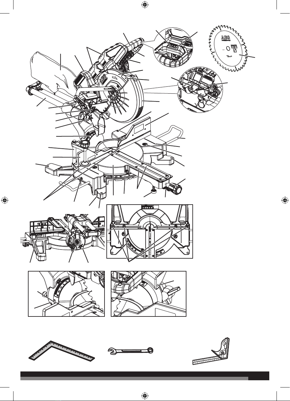
The following tools (not included) are needed for making adjustments:
COMBINATION SQUARECOMBINATION WRENCHFRAMING SQUARE
Ø 254 mm
n
max.
7000
Ø 30 mm
48HW 2.2mm
42
43
41
1
7
8
9
11
13
14
15
16
17
18
19
20
21
23
25
26
33
35
34
10
12
12
36
40
12
24
12
32
28
29
31
30
27
4
22
37 3938
23
6
5
1. “D” Handle
2. Laser button
3. LED button
4. Saw blade
5. LED light
6. Spindle lock button
7. Switch trigger
8. Lower guard lock out lever
9. Upper blade guard
10. Laser guide
11. Lower blade guard
12. Mouting hole
13. Right sliding fence
14. Extension bar
15. “No hands zone” boundary line
16. “No hands zone” label
17. Mitre lock knob
18. Detent release lever
19. Balancing foot
20. Throat plates
21. Mitre scale
22. Turning table
23. Saw base
24. Blade wrench
25. Fixed fence
26. Left sliding fence
27. Work clamp
28. Bevel scale
29. Depth stop
30. Head lock pin
31. Depth control knob
32. Sliding lock knob
33. Slide bar
34. Dust bag
35. Carrying handle
36. Battery pack
37. Sliding fence adjustment knob
38. Bevel lock knob
39. Single/dual bevel selector
40. Screws for fixing fence
41. 0° bevel stop screw
42. Right bevel angle adjusting screw
43. Left bevel angle adjusting screw

4
4
1- Mounting holes
2 - Mounting surface
3 - Base
Fig. 1
Fig. 2
2
11
3
2
1
3
Fig. 3
1
3
2
4
1 - Right sliding fence
2 - Slot
3 - Sliding fence adjustment knob
1 - Work clamp
2 - Base
3 - Single/dual bevel selector
4 - Work clamp knob
Fig. 4
Fig. 5
2
1
1 - Exhaust port
2 - Dust bag
1 - Extension bar
2 - Blade wrench
1
2
55
Fig. 6
1 - Mitre indicator screw
2 - Mitre scale indicator
3 - Detent release lever
4 - Mitre lock knob
5 - Miter scale
4
5
3
1
2
Fig. 8
1 - Fixed fence
2 - Mitre lock knob
3 - Detent release lever
4 - Turning table
5 - Framing square
6 - Saw blade
Fig. 7
1 - Indicator screw
2 - Scale indicator
3 - Bevel scale
1
3
4
1
6
2
3
5
Fig. 9
2
6
6
1
Fig. 10
1 - Saw blade
2 - Framing square
3 - Turning table
4 - Fixed fence
3
4
1
2
Fig. 12
Fig. 11
Fig. 13
View of blade not square with
fence, adjustments are required.
1 - Mitre scale indicator
2 - Mitre scale
3 - Mitre detent
1 - Screws for fixing fence
2 - Fence
1 - Mitre lock knob
2 - Detent release lever
3 - Detent override
23
1
2
1
4
2
3
2
1
77
Fig. 15
Fig. 14
Fig. 16
Fig. 17
1 - Saw blade
2 - Combination square
3 - Turning table
1 - Dust-proof cover
View of blade not square with
turning table, adjustments are required.
1
2
3
1
2
1
Ø 254 mm
n
max.
7000
Ø 30 mm
48HW 2.2mm
Note: Before use, replace
blade bolt cover screw and
tighten securely to prevent
blade bolt cover movement
6
17
4
3
2
8
To tighten
To loosen
1
1 - Blade bolt cover screw
2 - Outer flange
3 - Blade bolt
4 - Saw blade
5 - Inner flange
6 - Blade bolt cover
7 - Lower blade guard
8 - Blade wrench
9 - Spindle lock button
2
3
4
5
9
8
8
1 - Laser button
2 - Red line
Fig. 18 Fig. 20
Fig. 19
1 - “D” handle
2 - Head lock pin
1 - Depth stop
2 - Depth control knob
1
2
1
2
1
2
99
Cross cut
1 - Work clamp
2 - Mitre detent release button
3 - Mitre lock knob
Fig. 21
Fig. 22
1 - LED button
Fig. 23
Fig. 24
1 - Push back
1
3
2
Shadow of
blade teeth
projected
onto workpiece
1 - Sliding lock knob
2 - Slide cut
3 - Pull lower guard lock lever
4 - Slide saw arm forward, pull lower guard lock out lever
to unlock lower guard, then push down.
4
3
2
1
1
1
10
10
Bevel cut
1 - Bevel lock knob
2 - Single/dual bevel selector
Fig. 25
Fig. 26
Mitre cut
1 - Work clamp
1
1
Bevel cut
1 - Work clamp
Fig. 28
Compound mitre cut
1 - C-clamp (not included)
Fig. 27
1
2
2

11 11
Fig. 30
Fig. 32
Fig. 31
1 - Wide board
1
23
Ceiling
Wall
38°
52°
2
Top edge against fence:
Left side, inside corner
Right side, outside corner
1
Ceiling
Wall
45°
45°
1
4
3
Top edge against fence:
Left side, inside corner
Right side, outside corner
2
1 - Cut these grooves with saw
2 - Use a chisel to cut out the middle
3 - Workpiece
1 - Inside corner
2 - Sliding fence
3 - Outside corner
4 - Turning table
1 - Sliding fence
2 - Turning table
1 - Long workpiece
2 - Workpiece supports
2
1
1
Fig. 29
12
12
Fig. 33
Fig. 34
Fig. 35
Right
Fig. 36
Fig. 37
Wrong
1 - Spring clamp (not included)
2 - Molding
3 - Sliding fence
3
1 - 0º Bevel stop screw
1 - Left bevel angle adjusting screw
2 - Right bevel angle adjusting screw
Fig. 38
2
1Bottom edge against fence:
Left side, inside corner
Right side, outside corner
1 - Sliding fence
2 - Spring clamp (not included)
3 - Turning table
Crown molding nested against front facing mitre fence
2
13
1
2
1
13 13
Fig. 41
Fig. 42
1 - Throat plates
1 - Throat plates
2 - Mitre lock knob
2
1
Fig. 40
1
2
1
Fig. 39
1 - Rivets
2 - Guard block
1 - Laser adjustment screw #1
2 - Laser adjustment screw #2
3 - Laser adjustment screw #3
2
Unlock
Lock
1
1
3
2

14
14
TECHNICAL DATA SLIDE COMPOUND MITRE SAW PSD18B-254X
Voltage DC 18 V
Maximum cutting depth 91 mm
No-load speed 3900 min-1
Weight - excluding battery pack 15.6 kg
Saw blade diameter x hole diameter 254 x 30 mm
Saw blade thickness / kerf 1.6 mm / 2.2 mm
Maximum cutting capacity
Mitre 0°/ Bevel 0° 90 mm × 305 mm
Mitre 0°/ Bevel 45° (R) 39 mm × 305 mm
Mitre 0°/ Bevel 45° (L) 43 mm × 305 mm
Mitre Left 45°/ Bevel 0° 90 mm × 215 mm
Mitre Right 45°/ Bevel 0° 50 mm × 215 mm
Mitre 45°/ Bevel 45° (R) 39 mm × 215 mm
Mitre 45°/ Bevel 45° (L) 43 mm × 215 mm
Vertical Base
Mitre Left 45°/ Bevel 0° 19.1 mm × 105 mm
Mitre Right 45°/ Bevel 0° 19.1 mm × 88.9 mm
Nested Crown
Mitre 45°/ Bevel 0° 88.9 mm
Minimum workpiece dimensions 215 mm × 35 mm × 2.5 mm
Laser class Class 1
Laser wavelength λ 650 nm
Laser maximum power 1 mW
Measured values determined according to EN61029
A-weighted sound pressure level LP= 89.0 dB(A)
Uncertainty K K = 3 dB(A)
Measured values determined according to EN61029
A-weighted sound power level LW= 98.5 dB(A)
Uncertainty K K = 3 dB(A)
The vibration total values (triaxial vector sum) determined according to EN61029
Vibration emission value ah= 1.1 m/s2
Uncertainty K K = 1.5 m/s2
REPLACEMENT PARTS
Saw blade 089292001099
Combination wrench 089292001078
Dust chute rubber 089292001111
Work clamp 089292001800
Dust bag 089292001705
BATTERY AND CHARGER
Compatible battery pack
(not included)
Compatible charger
(not included)
L1815R
L1820R
L1825R
L1830R
L1840R
L1850R
L1860R
AL1218G
BL1218
BLK1218
Use AEG 18V battery and charger only.

15 15
WARNING!
Read all safety warnings and all instructions. Failure to follow
the warnings and instructions may result in electric shock, re and/
or serious injury.
Save all warnings and instructions for future reference.
GENERAL SAFETY WARNINGS
WARNING
When using electric tools, basic safety precautions should
always be followed to reduce the risk of re, electric shock and
personal injury. Read all these instructions before attempting to
operate this product and save these instructions.
Keep work area clear. Cluttered areas and benches invite injuries.
Consider work area environment. Do not expose tools to rain. Do
not use tools in damp or wet locations. Keep work area well lit. Do
not use tools in the presence of ammable liquids or gases.
Guard against electric shock. Avoid body contact with earthed
or grounded surfaces (e.g. pipes, radiators, ranges, refrigerators).
Keep other persons away. Do not let persons, especially children,
be involved in the work, touch the tool or the extension cord, and
keep them away from the work area.
Store idle tools. When not in use, tools should be stored in a dry
locked-up place, out of reach of children.
Do not force the tool. It will do the job better and safer at the rate
for which it was intended.
Use the right tool. Do not force small tools to do the job of a heavy
duty tool. Do not use tools for purposes not intended, for example,
do not use circular saws to cut tree limbs or logs.
Dress properly. Do not wear loose clothing or jewellery, they can
be caught in moving parts. Non-skid footwear is recommended
when working outdoors. Wear protective hair covering to contain
long hair.
Use protective equipment. Use safety glasses. Use face or dust
mask if working operations create dust.
Connect dust extraction equipment. If the tool is provided for
the connection of dust extraction and collecting equipment, ensure
these are connected and properly used.
Do not abuse the cord. Never yank the cord to disconnect it from
the socket. Keep the cord away from heat, oil and sharp edges.
Secure work. Where possible, use clamps or a vice to hold the
work. It is safer than using your hand.
Do not overreach. Keep proper footing and balance at all times.
Maintain tools with care. Keep cutting tools sharp and clean for
better and safer performance. Follow instruction for lubricating
and changing accessories. Inspect tool cords periodically and if
damaged, have them repaired by an authorised service facility.
Inspect extension cords periodically and replace if damaged. Keep
handles dry, clean and free from oil and grease.
Disconnect tools. When not in use, before servicing and when
changing accessories such as blades, bits and cutters, disconnect
tools from the power supply.
Remove adjusting keys and wrenches. Form the habit of
checking to see that keys and adjusting wrenches are removed
from the tool before turning it on.
Avoid unintentional starting. Ensure switch is in “off” position
when installing battery pack.
Use outdoor extension leads. When the tool is used outdoors,
use only extension cords intended for outdoor use and so marked.
Stay alert. Watch what you are doing, use common sense and do
not operate the tool when you are tired.
Check damaged parts. Before further use of tool, it should be
carefully checked to determine that it will operate properly and
perform its intended function. Check for alignment of moving parts,
binding of moving parts, breakage of parts, mounting and any other
conditions that may affect its operation. A guard or other part that is
damaged should be properly repaired or replaced by an authorised
service centre unless otherwise indicated in this instruction manual.
Have defective switches replaced by an authorised service centre.
Do not use the tool if the switch does not turn it on and off.
Warning. The use of any accessory or attachment other than the
one recommended in this instruction manual may present a risk of
personal injury.
Have your tool repaired by a qualied person. This electric tool
complies with the relevant safety rules. Repairs should only be
carried out by qualied persons using original spare parts otherwise
this may result in considerable danger to the user.
MITRE SAW SAFETY WARNINGS
Always clamp the workpiece safely and securely.
Ensure that the machine is always stable and secure (e.g. xed to
a bench).
Always wear ear protectors. Exposure to noise can cause hearing
loss.
Always wear safety goggles when using the machine. It is
recommended to wear gloves for handling blades and rough
material, as well as sturdy non-slip shoes which also protect the
feet from workpieces that may fall from the cutting area.
Always remove the plug or battery pack before carrying out any
adjustment, maintenance or cleaning on the machine.
Ensure the machine is switched off before installing or removing
the battery pack.
Do not stand in a line with the saw blade in front of the machine.
Always stand aside of the saw blade.
Keep hands, ngers, and arms away from the rotating saw blade.
Never reach into the area near the blade, unless the blade has
completely stopped.
Before use, thoroughly check the tool for any damage or material
fatigue. Repairs should only be carried out by authorised service
agents.
Always use the guards on the machine. Do not use the machine if
the guards are not in place and working correctly.
Do not clamp the protective swing guard.
If the workpiece or blade becomes jammed, turn the mitre saw
“OFF”. Wait for all moving parts to stop and disconnect the plug
from the power source and/or remove the battery pack. Then work
to free the jammed material.
Never alter of modify the saw or its function. Your safety may be
compromised.
Do not use saw blades which are cracked, damaged, or deformed.
Do not use saw blades made of high-speed steel.
Only use saw blades which are sharp. Replace blunt blades with a
new replacement.
Use a blade holder or wear gloves when handling a saw blade.
Always use blades with the correct size and shape of arbour holes.
Blades that do not match the mounting hardware of the saw will run
eccentrically, causing loss of control.
Use only woodworking blades specied in this manual, which
comply with EN 847-1.
Do not use any anges, washers, and nuts to secure the saw blade
other than those supplied or indicated in the instruction manual.
It is essential to adhere to the maximum speed specied on the
saw blade.
It is necessary to select a saw blade which is suitable for the
material being cut.
Never use the mitre saw to cut materials other than those specied

16
16
in the intended use section in this manual.
Replace the table insert when worn or damaged.
Before work, make a dummy cut without the motor turned on so the
position of the blade, operation of the guards with respect to other
machine parts, and workpiece may be checked.
Refrain from removing any cut-offs or other parts of the workpiece
from the cutting area while the machine is running and the saw head
is not in the rest position.
When transporting the machine, use only transportation devices
and never use guards for handling or transportation.
The handle lock must always be engaged when transporting the
mitre saw.
Keep the oor area free of loose material e.g. chips and cut-offs.
Long workpieces must be adequately supported.
Stock having a round or irregular cross section (such as rewood)
which cannot be clamped securely by the provided clamp must
not be cut. When sawing into the edge of thin or layered stock, a
suitable auxiliary fence must be used to provide support.
The dust produced when using this tool may be harmful to health.
Use a dust suction system and wear a suitable dust protection
mask. Remove deposited dust thoroughly, e.g. with a vacuum
cleaner.
Connect the saw to a dust-collecting device when sawing wood.
Do not replace the LED or laser with a different type. Any repairs
must only be carried out by the manufacturer or authorised service
agent.
SAFETY INSTRUCTIONS FOR WOOD CUTTING BLADE
Please read the manual and instructions carefully before using the
saw blade and the machine.
The machine must be in good condition, the spindle without
deformation and vibration.
Do not use the saw without the guards in position, keep guards in
good working order and properly maintained.
Ensure the operator is adequately trained in safety precautions,
adjustment, and operation of the machine.
Always wear goggles and ear protection when using the machine. It
is recommended to wear gloves, sturdy non-slip shoes and apron.
Before using any accessory, consult the instruction manual. The
improper use of an accessory can cause damage and increase the
potential for injury.
Use only blades specied in this manual, complying with EN 847-1.
Observe the maximum speed marked on the saw blade. Ensure
the speed marked on the saw blade is at least equal to the speed
marked on the saw.
Always use blades with correct size and shape of arbour holes.
Blades that do not match the mounting hardware of the saw will run
eccentrically, causing loss of control.
Do not use blades of larger or smaller diameter other than
recommended. Do not use any spacers to make the blade t onto
the spindle.
Check the tips of the saw blade for damage or abnormal appearance
before each use. Tips that are damaged or loose can become ying
objects in use and increase the chance of personal injury.
Do not use cracked or distorted saw blades. Do not use saw blades
that are damaged or deformed.
Scrap the saw blade if damaged, deformed, distorted or cracked,
repairing is not permitted.
Do not use HSS blades.
Ensure the saw blade is mounted correctly, tighten the arbor nut
securely before use (tightening torque approx. 12 Nm).
Fastening screw and nuts shall be tightened using the appropriate
spanner, etc.
Extension of the spanner or tightening using hammer blows is not
permitted.
Make sure the blade and anges are clean and the recessed sides
of the collar are against the blade.
Make sure the blade rotates in the correct direction.
Before work, make a dummy cut without the motor turned on so the
position of the blade, operation of the guards with respect to other
machine parts and workpiece may be checked.
Never leave the machine unattended.
Do not apply lubricants on the blade when it is running.
Never perform any cleaning or maintenance work when the machine
is still running and the head is not in the rest position.
Never attempt to stop a machine in motion rapidly by jamming a tool
or other means against the blade, serious accidents can be caused
unintentionally in this way.
Disconnect the saw from the mains supply or remove battery pack
before changing blades or carrying out maintenance.
Pay attention to blade packing and unpacking, it is easy to be
injured by the sharp blade tips.
Use a blade holder or wear gloves when handling a saw blade.
Keep and store the blade in original packaging or other suitable
packaging, keep in dry conditions and away from chemicals which
may damage the blade.
LASER SAFETY RULES
■The laser radiation used in this saw is Class 1 with maximum
<1mW and 650nm wavelengths. Do not view directly with
optical instruments. Failure to comply with the rules could result
in serious personal injury.
■Do not stare into beam during operation.
■Do not project the laser beam directly into the eyes of others.
Serious eye injury could result.
■Do not place the laser in a position that may cause anyone to
stare into the laser beam intentionally or unintentionally.
■Do not use optical tools to view the laser beam.
■Do not operate the laser around children or allow children to
operate the laser.
■Do not attempt to repair the laser device by yourself.
■Do not attempt to change any parts of the laser device by
yourself.
■Any repairs must only be carried out by the laser manufacturer
or authorized service agent.
■Do not replace the laser with a different type.
SPECIFIED CONDITIONS OF USE
The slide compound mitre saw is intended for sawing solid and
bonded wood with or without glued veneer, plastics, and materials
similar to wood.
The slide compound mitre saw is intended to be used only by adult
operators who have read the instruction manual and understand the
risks and hazards.
The slide compound mitre saw is designed to be xed at the base
to a solid bench top. If the base is not securely xed, the whole
machine may move during cutting operations, which increases the
possibility of serious personal injury.
The slide compound mitre saw is designed make bevel and mitre
cuts. The capacities for the various cuts are provided in the product
specications in this manual.
The slide compound mitre saw is to be used in dry conditions, with
excellent ambient lighting and adequate ventilation.
The slide compound mitre saw is intended for consumer use and
should only be used as described above and is not intended for
any other purpose.

17 17
RESIDUAL RISKS
Even when the slide compound mitre saw is used as prescribed,
it is still impossible to completely eliminate certain residual risk
factors. The following hazards may arise and the operator should
pay special attention to avoid the following:
■Risk of contact with uncovered parts of the rotating saw blade.
■Kick-back of work pieces or parts of work pieces due to improper
adjustment or handling.
■Catapulting of faulty carbide tips from the saw blade. Wear Eye
protection at all times.
■Damage to the respiratory system. Wear respiratory protection
masks containing filters appropriate to the materials being
worked. Ensure adequate workplace ventilation. Do not eat,
drink or smoke in the work area.
■Damage to hearing if effective hearing protection is not worn.
WARNING
Dust from certain paints, coatings, and materials may cause
irritation or allergic reactions. Dust from wood such as oak,
beech, MDF, and others are carcinogenic. Materials containing
asbestos should only be worked on or processed by qualied
specialist operators.
WARNING
Injuries may be caused or aggravated by prolonged use of a
tool. When using any tool for prolonged periods, ensure you take
regular breaks.
ASSEMBLY
UNPACKING
Packing list
■Dust bag x 1
■Work clamp x 1
■Left sliding fence x 1
■Right sliding fence x 1
■Extension bar x 2
■Dust chute rubber x 1
■L1860R battery pack x 2 (PSD18B-254-062 only)
■Charger x 1 (PSD18B-254-062 only)
■Operator’s manual x 1
■Battery manual x 1 (PSD18B-254-062 only)
■Charger manual x 1 (PSD18B-254-062 only)
The product requires assembly.
Carefully lift saw from the carton by the carrying handle and the saw
base, and place it on a level work surface.
The product has been shipped with the saw arm secured in the
down position. To release the saw arm, push down on the top of the
saw arm, cut the tie-wrap, and pull out the head lock pin.
WARNING
The saw arm is spring loaded. Hold the handle down to prevent
saw arm from snapping up when cutting the tie-wrap. Failure to
do so could result in possible serious injury.
■Lift the saw arm by the handle. Hand pressure should remain on
the saw arm to prevent sudden rise upon release of the tie wrap.
■Inspect the product carefully to make sure no breakage or
damage occurred during shipping.
■Do not discard the packing material until you have carefully
inspected and satisfactorily operated the product.
■The product is factory set for accurate cutting. After assembling
it, check for accuracy. If shipping has influenced the settings,
refer to specific procedures explained in the manual.
WARNING
If any parts are damaged or missing, do not operate the product
until the parts are replaced. Use of the product with damaged or
missing parts could result in serious personal injury.
WARNING
Do not attempt to modify the product or create accessories not
recommended for use with the product. Any such alteration or
modication is misuse and could result in a hazardous condition
leading to possible serious personal injury.
WARNING
To prevent accidental starting that could cause serious personal
injury, always remove the battery packs from the product when
assembling parts.
INSTALLING EXTENSION BARS
See gure 1.
Insert each of the extension bars in the holes at the side of the saw
base. Align the holes on the bars and under the saw base. Tighten
with screws.
MOUNTING HOLES
See gure 2.
WARNING
Before starting any cutting operation, mount the product to a
solid workbench. Never operate the product on the oor or in
a crouched position. Failure to heed this warning can result in
serious personal injury.
The product should be mounted to a rm supporting surface such
as a workbench, mounting board. Four bolt holes have been
provided in the saw base for this purpose. Each of the four mounting
holes should be bolted securely using 7.9 mm (5/16 in.) machine
bolts, lock washers, and hex nuts (not included). Bolts should be
of sufcient length to accommodate the saw base, lock washers,
hex nuts, and the thickness of the workbench. Tighten all four bolts
securely.
The hole pattern for mounting to a workbench is shown in gure 1.
Carefully check the workbench after mounting to make sure that no
movement can occur during use. If any tipping, sliding, or walking is
noted, secure the workbench to the oor before operating.

18
18
CARRYING HANDLE
WARNING
Only use the lift handles on the table and/or the carrying handle
on top to move or carry the product. Never use the “D” handle and
always remove the battery before moving. Carrying the product
with the “D” handle may cause inadvertent switch actuation and
may result in serious personal injury.
BLADE WRENCH
A blade wrench is packed with the product. One end of the wrench
is a Phillips screwdriver and the other end is a hex key. Use the
hex key end when installing or removing blade and the Phillips end
when removing or loosening screws. A storage area for the blade
wrench is located at the left side of the saw base.
INSTALLING SLIDING FENCE
See gure 3.
■Turn the sliding fence adjustment knob counterclockwise, to
clear fence slots.
■Install the sliding fence. Lower fence into fence slot. Be sure
side of fence lines up flush with side of fixed fence.
■Tighten sliding fence adjustment knob securely.
NOTE: To remove the sliding fence, loosen the sliding fence
adjustment knob. Then, slide the fence towards the blade to take
out.
INSTALLING THE WORK CLAMP
See gure 4.
WARNING
In some operations, the work clamp assembly may interfere with
the operation of the blade guard assembly. Always make sure
there is no interference with the blade guard prior to beginning
any cutting operation to reduce the risk of serious personal injury.
The work clamp provides greater control by clamping the workpiece
to the table. It also prevents the workpiece from creeping towards
the saw blade.
Depending on the cutting operation and the size of the workpiece,
it may be necessary to use a C-clamp (not included) instead of the
work clamp to secure the workpiece prior to making the cut.
To install the work clamp:
■Place the shaft of the work clamp in either hole on the turning
table base.
■Rotate the work clamp knob on the work clamp to move it in or
out as needed.
NOTE: Many of the illustrations in this manual show only portions
of the product. This is intentional so that we can clearly show points
being made in the illustrations. Never operate the product without all
guards securely in place and in good operating condition.
DUST BAG
See gure 5.
■To install the dust bag and frame assembly, slide the open end
of the frame onto the exhaust port.
■For efficient operation, empty the dust bag before it is half full.
This will permit better air flow through the bag.
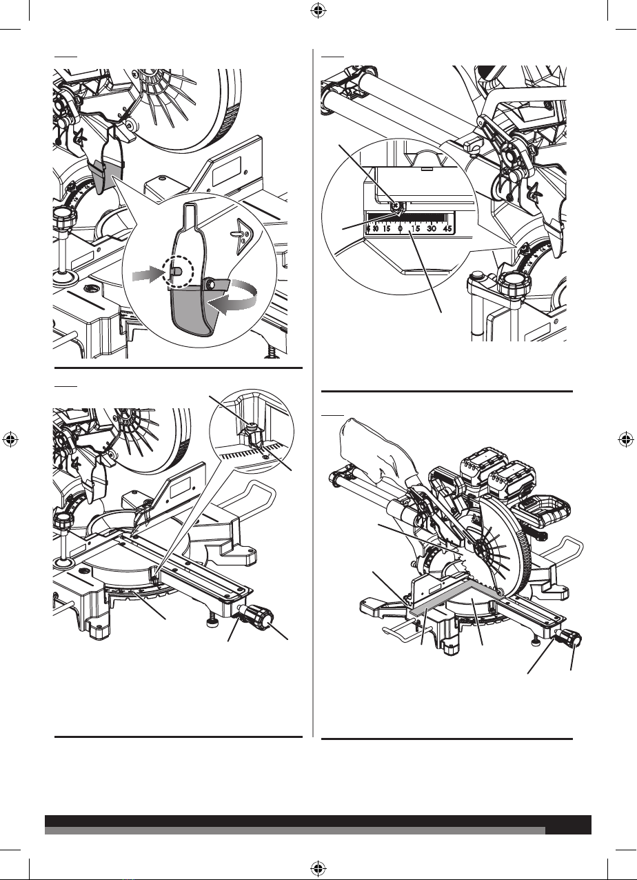
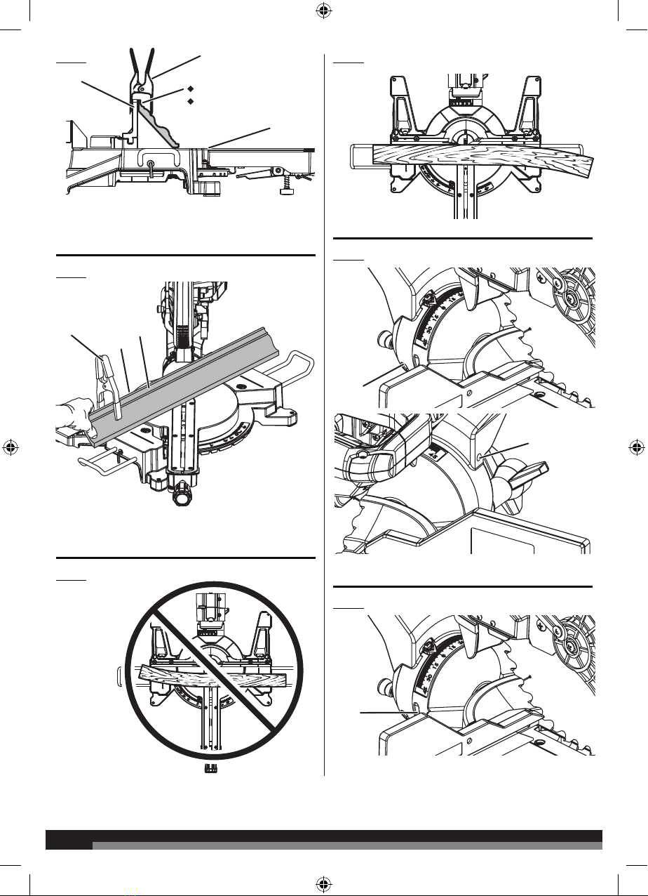
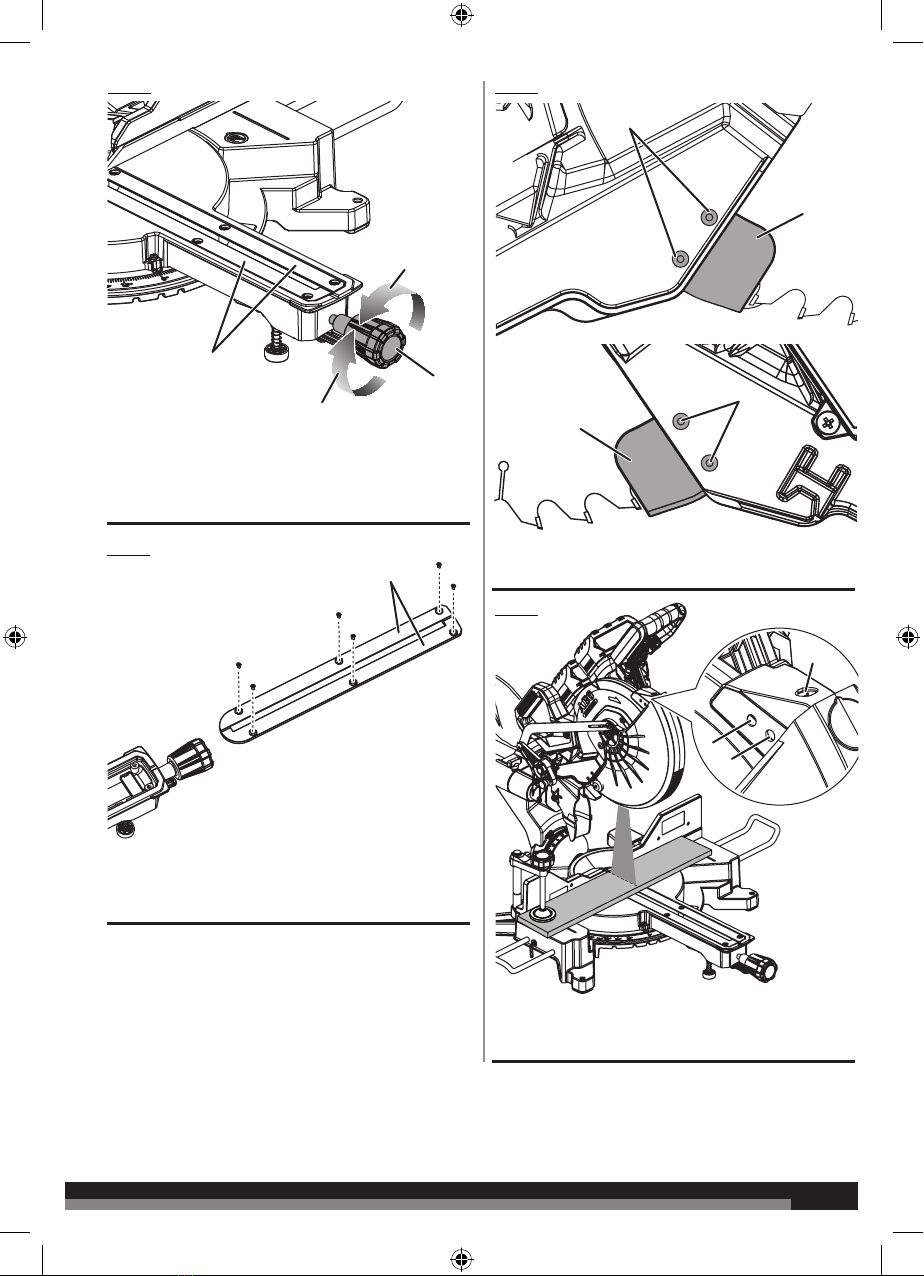
INSTALLING THE DUST CHUTE RUBBER
See gure 6.
The rubber part of the dust chute requires user assembly.
■Insert the tab on the dust chute rubber in the indent of the main
dust chute, so that the tab faces inward of the dust chute.
■Wrap the dust chute rubber around the main dust chute. Pass
the hole on the rubber through the tab on the main dust chute.
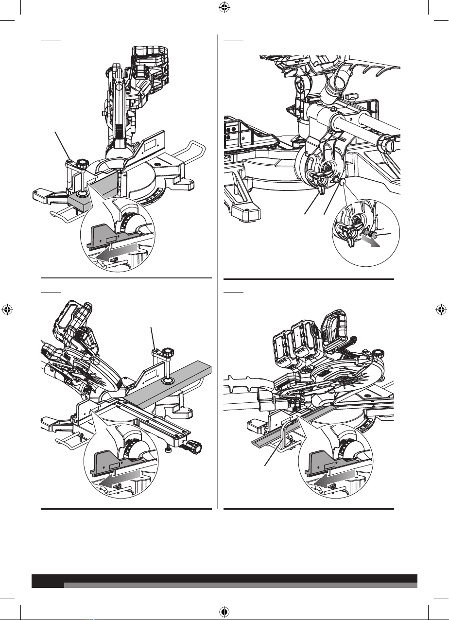
SQUARING THE SAW BLADE TO THE FENCE
See gures 7 - 13.
■Remove the battery packs from the product.
■Pull the saw arm all the way down and lock in transport position.
■Loosen the mitre lock knob to unlock the turning table.
■ Squeeze the detent release lever. Rotate the turning table until
the scale indicator is positioned at 0°.
■Release the detent release lever, and ensure the control arm is
seated in the positive notch.
■Tighten the mitre lock knob to secure the turning table.
■Loosen bevel lock knob and set saw arm at 0° bevel (blade set
90° to turning table). Tighten bevel lock knob.
■ Lay a framing square flat on the turning table. Place one leg of
the square against the fence. Slide the other leg of the square
against the flat part of saw blade.
NOTE: Make sure that the square contacts the flat part of the
saw blade, not the blade teeth.
■ The edge of the square and the saw blade should be parallel.
■If the front or back edge of the saw blade angles away from the
square, adjustments are needed. See figure 11.
■Refer to To adjust the mitre angle in the Adjustments section for
mitre angle adjustment.
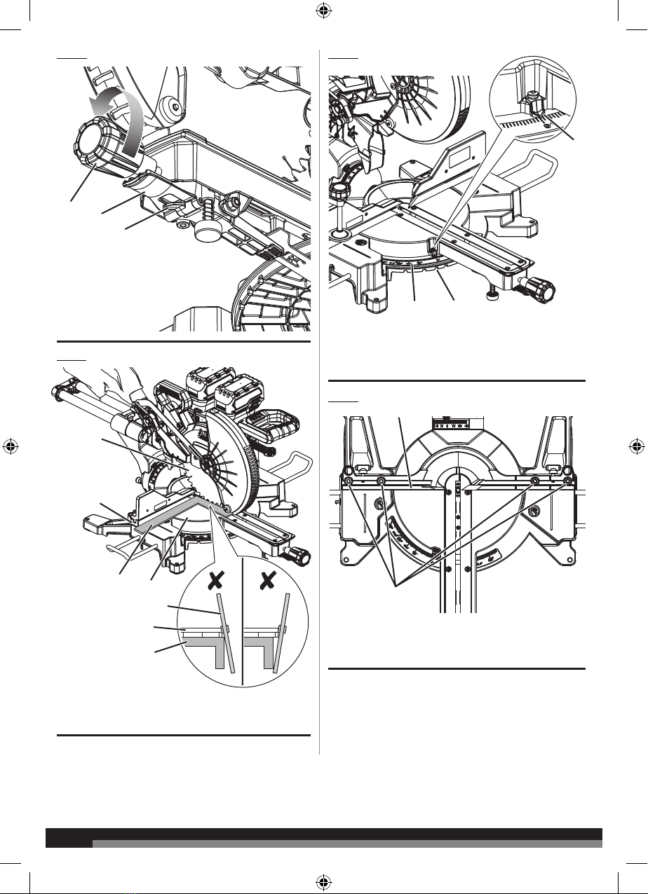
SQUARING THE BLADE TO THE TURNING TABLE
See gures 14.
To square the blade at 0°:
■Remove the battery packs from the product.
■Pull the saw arm all the way down and engage the head lock pin
to hold the saw arm in transport position.
■Loosen the mitre lock knob, then depress and hold the detent
release lever to release the turning table.
■Rotate the turning table until the scale indicator is positioned
at 0°.
■Release the detent release lever and allow the turning table to
engage the 0° detent position. Tighten the mitre lock knob to
secure the turning table.
■Push the single/ dual bevel selector inward. See figure 4.
■Loosen bevel lock knob and tilt saw arm until it is seated in the
positive 0° bevel stop (blade set 90° to turning table). Tighten
bevel lock knob.
■ Place a combination square against the turning table and the
flat part of saw blade.
NOTE: Make sure that the square contacts the flat part of the
saw blade, not the blade teeth.
■Rotate the blade by hand and check the blade-to-table
alignment at several points.
■ The edge of the square and the saw blade should be parallel.
■If the top or bottom of the saw blade angles away from the
square as shown in figure 14, adjustments are needed.
■Loosen the bevel lock knob.
■Adjust 0° bevel stop screw to bring saw blade into alignment
with the square. See 0° Bevel Adjustment in the Adjustments
section.
■Retighten bevel lock knob. Recheck blade-to-table alignment.
To square the blade at 45°:
■Loosen the bevel lock knob and set the saw arm at 45° bevel.

19 19
Tighten bevel lock knob.
NOTE: To obtain right bevel angles, pull the single/ dual bevel
selector out and tilt the saw to the desired angle.
■ Using a combination square, check the blade-to-table alignment
as described earlier.
■If adjustments are needed, refer to 45° Bevel Adjustment in the
Adjustments section.
■ The product has several scale indicators. After squaring
adjustments have been made, it may be necessary to loosen
the indicator screws and reset them to zero. See figures 7-8.
OPERATION
WARNING
Do not allow familiarity with products to make you careless.
Remember that a careless fraction of a second is sufcient to
inict severe injury.
WARNING
Always wear eye protection with side shields. Failure to do so
could result in objects being thrown into your eyes, resulting in
possible serious injury.
WARNING
Do not use any attachments or accessories not recommended
by the manufacturer of the product. The use of attachments or
accessories not recommended can result in serious personal
injury.
WARNING
To avoid serious personal injury, always tighten the mitre lock
knob and tighten the bevel lock knob securely before making a
cut. Failure to do so could result in movement of the control arm
or turning table while making a cut.
WARNING
Do not start the product without checking for interference
between the blade and the mitre fence. Damage could result
to the blade if it strikes the mitre fence during operation of the
product. Failure to heed this warning can also result in serious
personal injury.
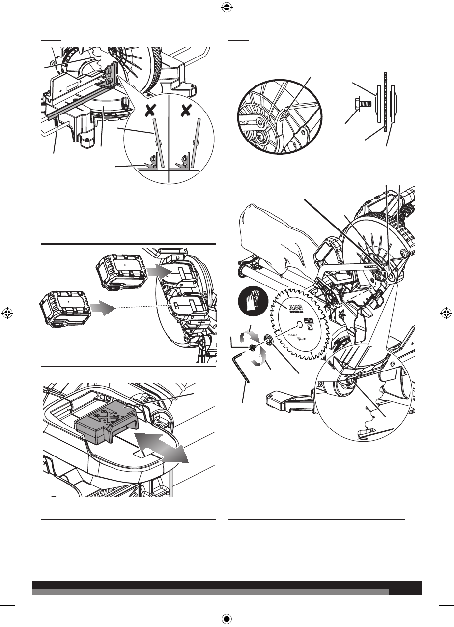
INSTALLING/REMOVING THE BATTERY PACKS
See gure 15.
■Place the battery packs in the product. Align the raised rib on
each battery pack with the groove inside the saw, then slide
each battery pack into the product.
■Make sure the latches on each side of the battery pack snap
into place and the battery pack is secured in the saw before
beginning operation.
■Depress the latches to remove the battery pack.
■For complete charging instructions, see the operator’s manuals
for your battery pack and charger.
WARNING
Always remove battery packs from the product when you are
assembling parts, making adjustments, cleaning, or when not in
use. Removing battery packs will prevent accidental starting that
could cause serious personal injury.
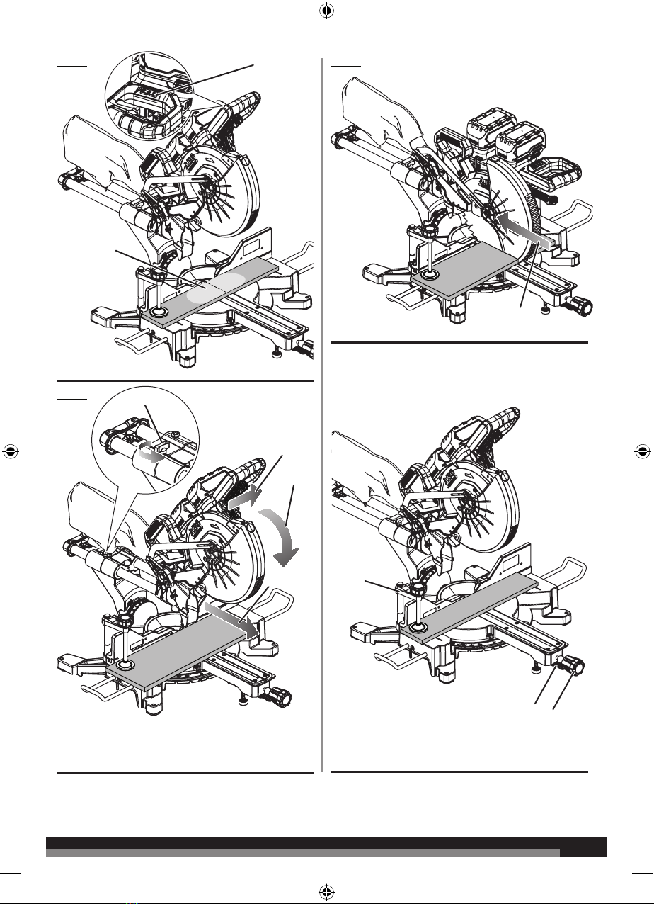
BATTERY PORT DUST COVER
See gure 16.
The battery port dust cover prevents dust from entering the battery
port. Cover the battery ports when battery packs are not in place.
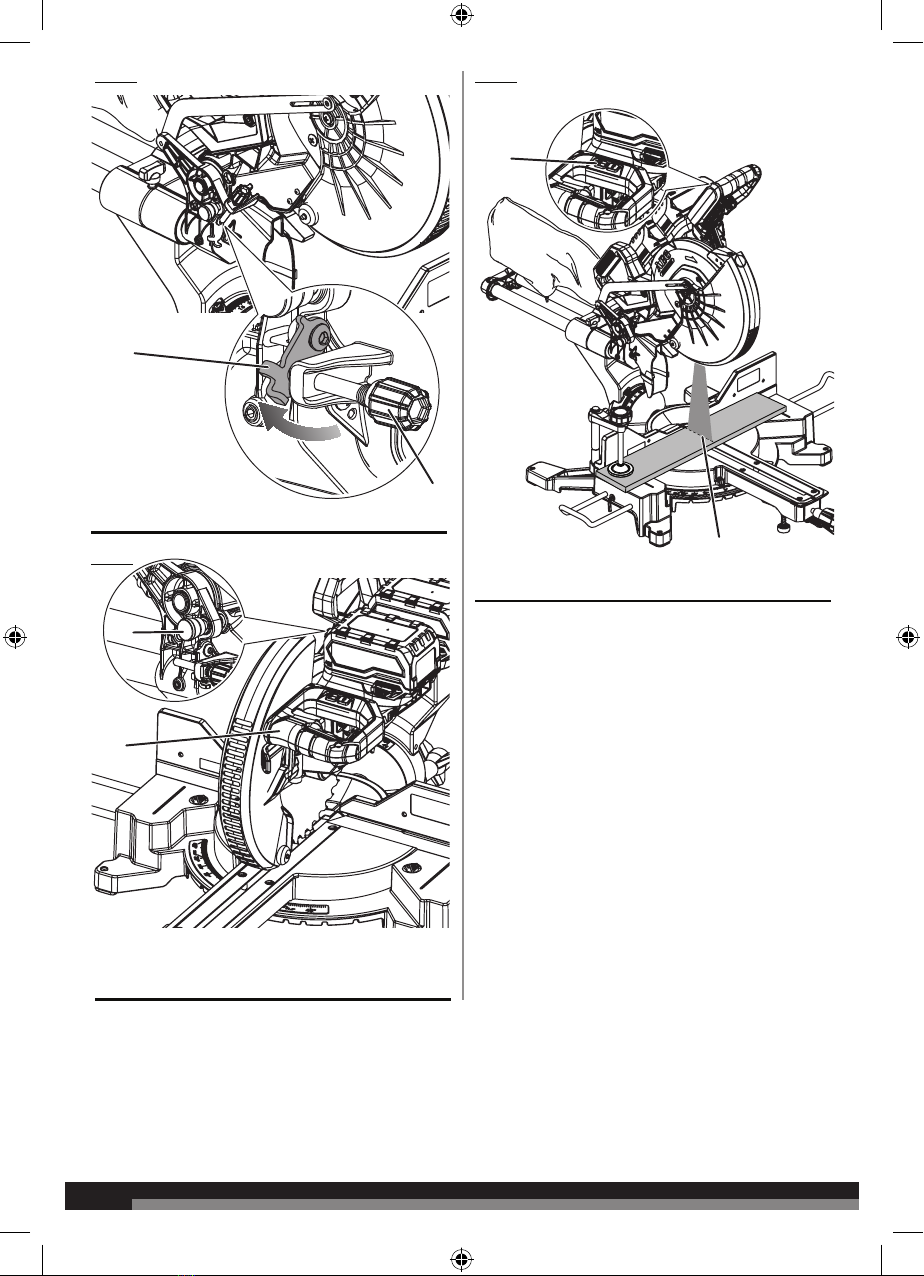
REPLACING THE BLADE
See gure 17.
WARNING
Before removing and tting the blade, make sure to wear safety
gloves.
WARNING
A 254 mm (10 in.) blade is the maximum blade capacity of the
product. Never use a blade that is too thick to allow outer ange
to engage with the ats on the spindle. Larger blades will come
in contact with the blade guards, while thicker blades will prevent
the blade bolt from securing the blade on the spindle. Either of
these situations could result in a serious accident and can cause
serious personal injury.
WARNING
Only use the blade specied in this manual and its speed is at
least equal to the speed marked on the product.
■Remove the battery packs from the product.
■Raise saw arm.
■Rotate lower blade guard up and loosen blade bolt cover screw.
Slide blade bolt cover towards upper blade guard to expose the
blade bolt.
■Depress the spindle lock button and rotate the blade bolt until
the spindle locks.
■Using the blade wrench provided, loosen and remove the blade
bolt.
NOTE: The blade bolt has left hand threads. Turn blade bolt
clockwise to loosen.
■Remove the outer flange. Wear gloves. Remove the blade.
Wear gloves when handling the saw blade.
■Wipe a drop of oil onto the inner flange and the outer flange
where they contact the blade.
WARNING
If inner ange has been removed, replace it before placing blade
on spindle. Failure to do so could cause an accident since blade
will not tighten properly.
■Wear gloves. Fit saw blade inside upper blade guard and onto
spindle. The blade teeth point downward at the front of saw as
shown in figure 17.
■Replace the outer flange. The double “D” flats on the blade
washers align with the flats on the spindle.
■Depress spindle lock button and replace blade bolt.
NOTE: The blade bolt has left hand threads. Turn blade bolt

20
20
counterclockwise to tighten.
WARNING
Always install the blade with the blade teeth and the arrow
printed on the side of the blade pointing down at the front of
the saw. The direction of blade rotation is also stamped with an
arrow on the upper blade guard.
■Tighten blade bolt securely.
■Replace blade bolt cover and tighten blade bolt cover screw
securely.
■Lower the blade guard.
■Raise and lower the saw arm to ensure lower blade guard
functions correctly.
USING THE DEPTH GUIDE
See gure 18.
When used, the depth guide limits the downward travel of the blade
when cutting dadoes and other non-through cuts.
To use the depth guide:
■Remove the battery pack from the product.
■Rotate the depth stop outward.
■With the depth control knob touching the depth stop, adjust the
depth control knob by turning the knob until the desired depth
of cut is attained.
■Rotate the depth stop inward for normal through cuts.
NOTE: The depth stop must be pushed in before locking/unlocking
the saw arm.
LOCKING / UNLOCKING THE SAW ARM
See gure 19.
When locking and unlocking the saw arm, it is not necessary to
loosen the depth control knob, however the depth stop must be
pushed in.
To unlock and raise the saw arm:
■Firmly grasp the “D” handle and apply downward pressure while
at the same time pulling the head lock pin out and away from
the saw housing.
■Raise the saw arm.
To lock the saw arm:
■Pull the lower guard lock out lever to right side to unlock the
lower guard.
■Firmly grasp the “D” handle and apply downward pressure until
head stops. Push in the head lock pin towards the saw allowing
it to lock the saw into place.
CUTTING WITH THE PRODUCT
WARNING
Secure the workpiece to the mitre saw base. Use the clamp
provided and, where necessary, use additional clamps or
holding mechanisms to prevent unintentional movement of the
workpiece while cutting.
WARNING
Never move the workpiece or make adjustment to any cutting
angle while the saw is running and the blade is rotating. Any
slip can result in contact with the blade causing serious personal
injury.
WARNING
Do not try to cut narrow pieces using the sliding feature. Failure
to heed this warning could result in serious personal injury.
LASER GUIDE
See gure 20.
For more accurate cuts, a laser guide is included with the mitre saw.
When used properly, the laser guide makes accurate, precision
cutting simple and easy.
■To use the laser guide, press the laser switch. The laser guide
will automatically turn off after 10 seconds.
NOTE: The laser guide will automatically turn on when the
switch trigger is depressed.
LED LIGHTING SYSTEM
See gure 21.
The LED lighting system casts the shadow of the blade onto the
workpiece. This results in greater accuracy of cuts and requires no
adjustments.
■To use this feature, press the LED button. The LED light will
automatically turn off after 15 seconds.
NOTE: The LED light will automatically turn on when the switch
trigger is depressed.
■Bring the saw arm down so that the blade is approximately 6.3
mm (1/4 in.) from the workpiece. The shadow of the blade will
be projected onto the workpiece, indicating where the blade
teeth will make contact as the cut is made.
TO SLIDE CUT
See gures 22-23.
WARNING
Never make a cut by pulling the saw towards you as the blade
can climb on top of the workpiece and come towards you. Failure
to heed this warning could result in serious personal injury.
■The sliding feature will cut workpieces up to 305 mm (12 in.)
wide x 90 mm (3-1/2 in.) thick.
■ With the saw off, pull the saw arm forward. Squeeze the switch
trigger (let blade reach maximum speed), then push the blade
down on top of the workpiece then back towards the rear of the
saw to make a cut. Cuts are made by: pushing the saw blade
away from you and towards the bevel scale at the back of the
saw, stopping when the full rear position has been reached after
each cut. When the saw is running (turned on), never pull the
saw blade towards you or towards the front of the saw.
■Raise saw arm to its full height.
■Tighten the mitre lock knob to secure the turning table.
■Place the workpiece flat on the turning table securely against
the fence. If the board is warped, place the convex side against
the fence. If the concave edge of a board is placed against the
fence, the board could collapse on the blade at the end of the
cut, jamming the blade. See figures 35 - 36.
■When cutting long pieces of lumber or molding, support the
opposite end of the stock with a roller stand or with a work
surface level with the saw table. See figure 29.
■Align the cutting line on the workpiece with the edge of saw
blade.
■Loosen the sliding lock knob by turning the knob
counterclockwise.
■Press the LED button to project the blade’s shadow onto the
workpiece.
Table of contents
Other AEG Powertools Saw manuals


