Aegislink S-RF500 User manual

AEGISLINK
Wireless Interlinked Smoke Alarm
Model: S-RF500
User Manual
This user manual contains important information regarding the operation of your AEGISLINK smoke
alarm. Ensure you read this user manual fully before installing and operating the alarm. If you are installing
this smoke alarm for use by others, you must leave this manual (or a copy of it) with the end user.
Introduction
Thank you for purchasing our smoke alarm. This smoke alarm conforms with the European Standard EN
14604:2005+AC: 2008and is designed to detect smoke. Our product lineups are constantly expanding.
Product Profile
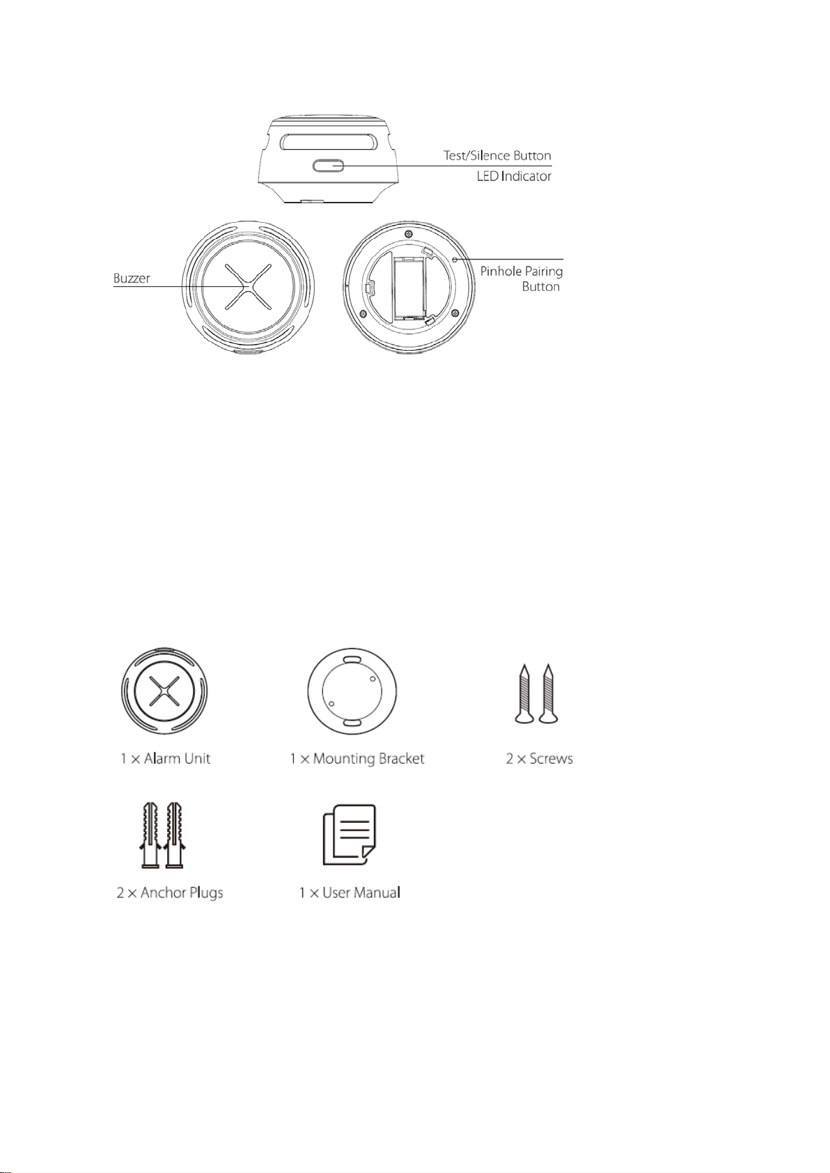
S-RF500
Buzzer
Test/Silence Button
LED Indicator
Pinhole Pairing Button
Package Contents
1 × Alarm Unit
1 × Mounting Bracket
2 × Screws
2× Anchor Plugs
1 × User Manual
1 × Pin

Safety Information
IMPORTANT!
1. DANGERS, WARNINGS, AND CAUTIONS ALERT YOU TO IMPORTANT OPERATING
INSTRUCTIONS OR TO POTENTIALLY HAZARDOUS SITUATIONS. PAY SPECIAL
ATTENTION TO THESE SITUATIONS.
2. THISALARM IS NOT INTENDED TOALERT HEARING IMPAIRED INDIVIDUALS. THE USE
OFALCOHOL OR DRUGS MAYALSO IMPAIR ONE’SABILITY TO HEAR THE SMOKE
ALARM.
3. FIRES IN CHIMNEYS, WALLS, ROOFS, DIFFERENT LEVELS OR BEHIND CLOSED DOORS
MIGHT NOT BE DETECTED.
4. THIS DEVICE DOES NOT DETECT FLAMES, HEAT, CARBON MONOXIDE OR OTHER
HAZARDOUS GASES.
WARNING!
1. NEVER IGNOREANYALARM. FAILURE TO RESPOND CAN RESULT IN SERIOUS INJURY
OR DEATH.
2. THE SILENCE FEATURE IS ONLY FOR YOUR CONVENIENCE AND WILL NOT CORRECTA
PROBLEM.ALWAYS CHECK YOUR HOME FOR APOTENTIAL PROBLEM AFTER ANY
ALARM. FAILURE TO DO SO CAN RESULT IN INJURY OR DEATH.
3. TEST THIS SMOKEALARM ONCEA WEEK. IF THE ALARM EVER FAILS TO TEST
CORRECTLY, REPLACE IT IMMEDIATELY! IF THE ALARM CANNOT WORK PROPERLY, IT
WILLNOT ALERTYOU TO A PROBLEM.
How to Set Up and Interconnect Wireless Alarms
All X-SENSE wireless interlinked alarms contain a built-in RF module that enables you to wirelessly connect 2
or more interlinked alarms and create an interlinked network. When one unit is triggered, all interconnected
alarms will sound. The X-SENSE series contain wireless interlinked smoke alarms, wireless interlinked carbon
monoxide alarms, and wireless interlinked combination smoke and carbon monoxide alarms. This model is
designed to be wirelessly interlinked with other X-SENSE alarms, but is not designed to communicate with
wireless interlinked alarms from other manufacturers.

The wireless interlinked alarms in one multi-pack have already been interconnected to each other, so
the alarms in each multi-pack have their own independent interlinked network. If you have more
than one multi-pack, you will need to connect them all to the same network, but you do not have to
disconnect each alarm individually. Choose one multi-pack as your base network and connect the
other multi-packs to it.
NOTE! The following instructions regarding wireless interconnection are applicable to X-SENSE
wireless interlinked alarms only.
How to Interconnect
1. Make sure you only work with 2 units at a time, and that they are both activated to ensure successful
connection.
NOTE: To activate your alarms, remove the back cover from the device and pull out the battery
insulating film from the battery compartment. To learn how to turn on different models of
wireless interlinked alarms, please refer to their specific user manuals for more details.
2. Press the pinhole pairing button on the back of one of the two units using the included pin. It will beep
once and the LED will flash red slowly, indicating it has entered pairing mode and is waiting for a new
unit to be added. Hold down the pinhole pairing button on the other unit until it beeps once and its
LED flashes red rapidly as it is searching for a unit to connect to.
3. After the search is successful and an interconnected group is created, both units will beep once and
automatically exit the interconnection mode. At this point, both units will only flash once every 60
seconds, indicating they are in normal standby mode.
4. If you want to connect a third alarm to this group, first activate the new device according to its
operating instructions. Press the pinhole pairing button on either of the two previously interconnected
units using the included pin, it will beep once and the LED will flash red slowly, indicating it has
entered pairing mode and is waiting for a new unit to be added. Hold down the pinhole pairing button
on the new unit until it beeps once and its LED flashes red rapidly as it searches for a network to
which it can connect. After the third unit successfully joins the interconnected network, both units will
beep once and automatically exit the interconnection mode.
5. If you want to connect more units, simply repeat step 4.Up to 24 alarms can be interconnected this
way. To ensure that all alarms enter the same interlinked network, make sure you only work
with 2 units at a time—one unit enters the pairing mode and the other unit enters the searching
mode.
6. Test the alarms according to the steps in the section “Alarm Test”.

NOTES
1. The alarm will enter the searching mode or the pairing mode for 60 seconds with the LED flashing red.
After 60 seconds, repeat step 2 to connect the alarms. If needed, press the pinhole pairing button once
while the alarm is in the searching mode or the pairing mode, and the LED will stop flashing red and
the alarm will quit the pairing mode to enter normal status.
2. Test all wireless alarms to ensure they are interconnected before installation.
3. A maximum of 24 wireless alarms can be interconnected on the same network.
4. The model can only be interconnected with other X-SENSEwireless interlinked alarms.
How to Disconnect
Press the pinhole pairing button using the pin and the unit will beep once. Then, hold down the pairing
button until the unit beeps once more to disconnect. After disconnecting, it can be reconnected to the same
network, or added to a new network.

Alarm Test
Be sure to test your alarms when you turn them on for the first time, or when the group configuration has
changed. In addition to the weekly tests you should perform, it is recommended to test the alarm after returning
from a long trip or vacation.
If your X-SENSE S-RF500is interconnected to other wireless alarms, we recommend that every individual
alarm is tested during the weekly test.
Test a Single Alarm Test All Interconnected Alarms
Action Press the test/silence button. Hold down the test/silence button.
Indication The alarm will beep3 times every 4
seconds.
The LED will flash red during the
test and give an audible signal.
After testing, the alarm will
automatically enter standby mode.
The initiating unit will beep continuously
with the LED flashing red.
Other interconnected unit
s in the
network will receive the signal after 5
seconds, then they will beep
continuously with the LED flashing red
and green successively. Release the
test/silence button and all the units will
stop testing.
The testing of the units should be
completed within 3 minutes.
After testing, the units will automatically
enter standby mode.
NOTE: The test function accurately tests the alarm’s smoke sensing circuit without the need to test with
smoke. If your smoke alarm fails to give an audible test signal, please refer immediately to the
troubleshooting guide at the end of this manual. Never use an open flame to test this device.
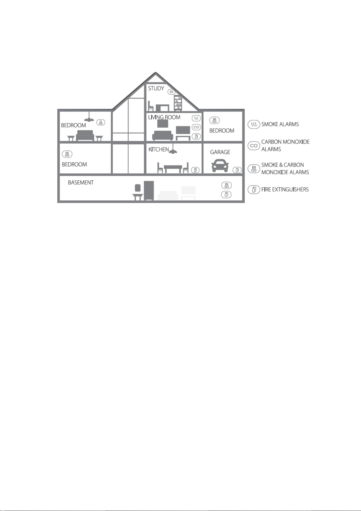
Installation Positioning
NOTE: If a smoke alarm is installed in a kitchen, ensure it has an accessible silence button, and install
it as far away from the stove and sink as possible to avoid false alarms.
①Study
②Bedroom
③Garage
④Living Room
⑤Kitchen
⑥Basement
⑦Smoke Detectors
⑧Carbon Monoxide Detectors
⑨Smoke & Carbon Monoxide Detectors
⑩Fire Extinguishers
1. Prioritize the installation of an alarm in the bedroom and walkways, and make sure you can hear the
alarm from all sleeping areas. In a home with several bedrooms, install an alarm in every bedroom. If
you install only one smoke alarm in your home, install the alarm near to all bedrooms where possible,
and not in a basement or furnace room.
2. Install an alarm above the stairway and on every floor of the house.
3. Smoke, heat and anything burning will spread horizontally after rising to the ceiling, so install the
alarm in the middle of the ceiling where possible. Ensure that the alarm is installed at the minimum
distance away from corner.
4. If an alarm cannot be installed in the middle of a ceiling, install it at a distance of 20 inches (50 cm)
away from the corners of the room.
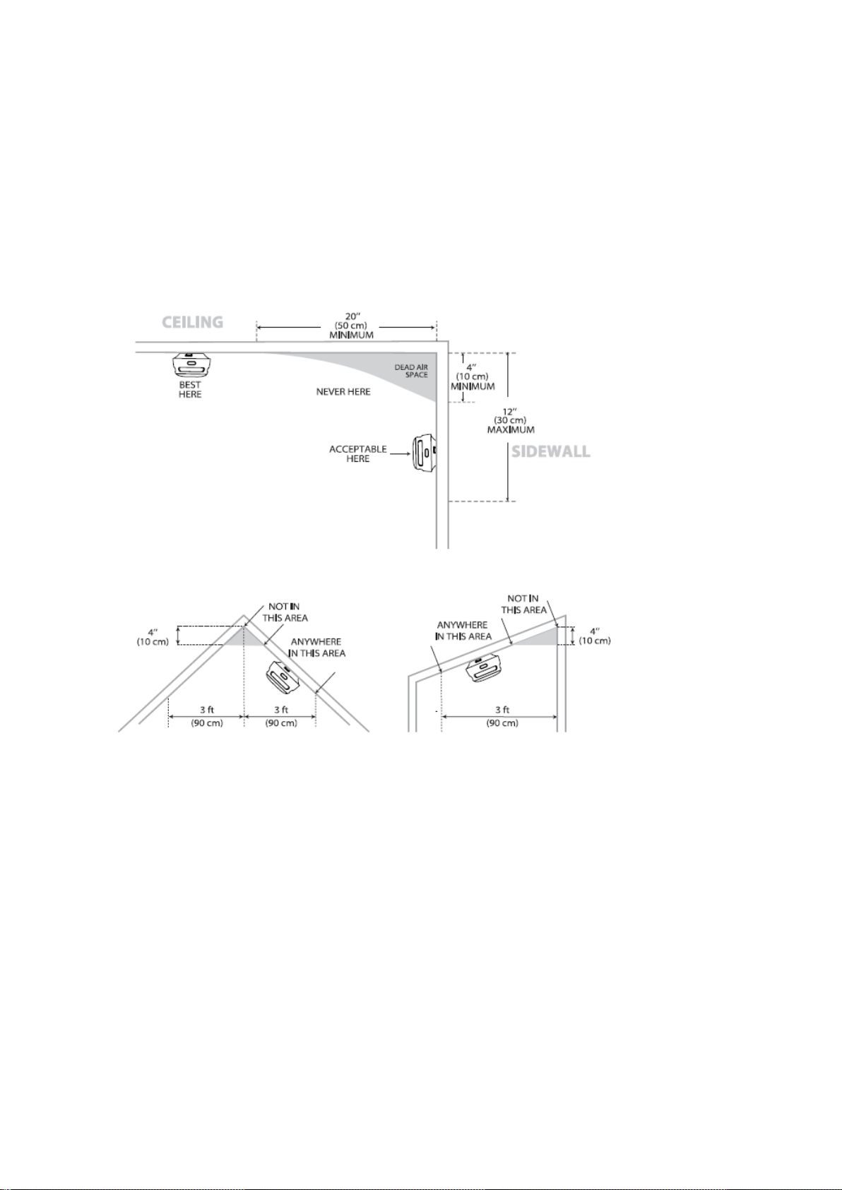
5. If an alarm is installed onto a wall, a distance of 4-12 inches (10-30 cm) should be kept below the
ceiling.
6. If the length of a room or hall is beyond 30 feet (900 cm), several alarms should be installed in the
same room.
7. When the wall or ceiling is angled, the alarm needs to be installed within 3 feet (90 cm) of the highest
wall or ceiling point (measured horizontally) in the room.
①CEILING
②SIDEWALL
③20″ (50 cm) MINIMUM
④4″ (10 cm) MINIMUM
⑤12″ (30 cm) MAXIMUM
⑥BEST HERE
⑦DEAD AIR SPACE
⑧NEVER HERE
⑨ACCEPTABLE HERE
⑩NOT IN THIS AREA
⑪ANYWHERE IN THIS AREA
⑫4″ (10 cm)
⑬3 ft (90 cm)

8. In multi-level houses or apartments, install at least one wireless smoke alarm on each level and keep
them installed in a straight vertical line (see diagram) with as few obstacles between each of the
interconnected alarms as possible to ensure optimal signal transmission.
LocationstoAvoid:
1. Near large metal surfaces and/or bundles of wire.
2. Near fluorescent lights, amateur radios, electrical equipment, or other devices that may transmit an RF
signal, as electronic “noise” may cause nuisance alarms.
WARNING!
1. THISALARM SHOULD BE INSTALLED BYACOMPETENT PERSON.
2. ALARMS SHOULD NOT BE USED AS A SUBSTITUTE FOR PROPER INSTALLATION, USE
AND MAINTENANCE OF FUEL BURNING APPLIANCES INCLUDING APPROPRIATE
VENTILATION AND EXHAUST SYSTEMS.
3. TO PREVENT INJURY, THIS DEVICE SHOULD BE SECURELYATTACHED TO THE CEILING
OR WALL IN ACCORDANCE WITH THE INSTALLATION INSTRUCTIONS.

4. BATTERIES SHOULD NOT BE EXPOSED TO EXCESSIVE HEAT SUCH AS DIRECT
SUNLIGHT, FIRE, ETC.
Installation Method
NOTE: Before installation, it is recommended to test the interconnected alarms in the rooms where you
intend to install them to ensure that they are within transmission range and that nothing will interfere
with their communication.
1. Use the mounting bracket to mark the screw holes on the ceiling or the wall.
2. Drill holes at the 2 marks using an appropriately-sized drill bit. Insert the anchor plugs and screw the
mounting bracket using the screws provided.
3. Attach the alarm to the mounting bracket and turn clockwise to lock the alarm.
4. Test the alarm according to the steps in the section “Alarm Test”.
Battery Replacement
1. To replace the battery, detach the smoke alarm from the mounting bracket by twisting
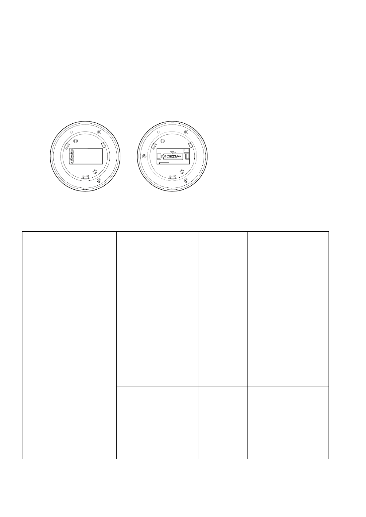
counterclockwise.
2. Pull the battery removal tab to remove the battery, and then install a new battery, matching the correct
polarity markings.
3. Test the alarm, and then mount the alarm onto the mounting bracket by twisting clockwise to lock the
alarm.
LED Indicator andAudible Alarm
Status LED indicator Audible alarm Action
Standby Mode
The LED flashes redonce
every 60 seconds. None.
Alarm Mode
Unit that detects
smoke and
initiates an alarm.
The LED flashes red 3 times
every 4 seconds.
3 quick beeps
every 4 seconds.
Dangerous smoke
concentration is detected.
Open nearby windows and
doors, and immediately move
to fresh air.
All other
interconnected
units in the
network.
The LED flashes red and
green 3 times sequentially
every 4 seconds.
3 quick beeps
every 4 seconds.
Dangerous smoke
concentration is detected by
the initiating unit in the
network. Please find the
initiating unit and take action.
The LED flashes red 4 times,
then
the LED flashes green
once every 5.8 seconds.
4 quick beeps
repeating every
5.8 seconds.
Dangerous CO concentration
is detected by the initiating
unit, and has reached the
alarm status.
Please find the initiating unit
and take action.
Ala
Green, Red & Yellow LED

Unit that detects
smoke and
initiates an alarm.
The LED flashes green once
every second for 5 seconds. None.
Alarm cancellation: When the
smoke concentration level
drops below the alarm
threshold, the alarm signal
will stop. Then, the alarm
goes back to the standby
mode.
Test
Test a single
unit.
The LED flashes red 3 times
every 4 seconds.
3 quick beeps
every 4 seconds. Press the test/silence button.
Test all
interconnected
units.
The LED indicator flashes red
rapidly. Continuous
beeping until
you release the
test/silence
button.
Initiating unit.
Hold down the test/silence
button on one unit in the
network.
The LED flashes red and
green sequentially.
Other interconnected alarms
in the network.
Silence Mode Red LED flashes once every 5
seconds. None. After 9 minutes, the unit will
exit silence mode.
Low Battery Red LED flashes once every
60 seconds.
1 beep every 60
seconds.
Each alarm gives an
independent warning.
Malfunction Red LED flashes twice every
40 seconds.
2 beeps every 40
seconds.
Each alarm gives an
independent warning.
Alarm Mode
The X-SENSE wireless interlinked alarms can be interconnected such that any unit that senses danger will
cause all other units in the interconnected network to alarm.
1. If the Initiating Unit Is Triggered by Smoke:
When one smoke alarm is triggered in the interconnected network, the unit will beep 3 times, paired with
the LED that flashes red every 4 seconds. Any other interlinked units will follow suit—they will beep 3
times every 4 seconds, paired with the LED flashing red and green in succession.

2. If the Initiating Unit Is Triggered by CO:
When one CO alarm is triggered in the interconnected network, the unit will beep 4 times every 5.8
seconds, paired with the LED flashing red.Any other interlinked units in the network will follow
suit—they will beep 4 times every 5.8 seconds, paired with the LED that flashes red 4 times first, followed
by the LED that flashes green once with every beep. When the CO concentration level drops below the
alarm threshold, the alarm will cease.
NOTES
When one unit is triggered, other interconnected units will sound. If the smoke alarm and CO
alarm are triggered in the network at the same time, the alarm signal of the smoke alarm will take
priority over that of the CO alarm.
This alarm has a relay function that extends the wireless interconnected network for wide detection
coverage.
Silence Mode
If you press the silence button during an alarm state, the unit will be in the silence mode for 9 minutes.
During the silence mode, the LED will flash red once every 5 seconds. The alarm will enter the normal
mode after 9 minutes.
NOTES
You can silence all interconnected units by pressing the test/silence button on one of the units. If
one unit is still alarming, it is the initiating unit (the unit that detected danger); to silence all
interlinked units, you must also press the test/silence button on the initiating unit.
While interconnected, the initiating unit cannot be triggered again during the 9-minute silence
duration. However, all other interconnected units can be triggered again if they detect danger
during the silence mode.
Technical Specifications
Power Supply Replaceable 3 V CR123A lithium battery
Operating Life 10 years

NOTES
Battery life is calculated on the current ratings in the standby mode with weekly testings. If its
operation mode changes to an alarming condition, the battery life will be decreased accordingly.
The smoke alarm functions between 40 and 100°F (4.4 and 37.8°C). Prolonged exposure to
temperatures outside of this range can reduce battery life and affect accuracy. We do not
recommend operating the device outside of this range.
Maintenance
To keep your smoke alarm in good working order, follow these simple steps:
1. Verify the unit's alarm sound and indicator are working properly by testing the unit once a week.
2. As a minimum your smoke alarm should be cleaned once every 3 months: Remove the unit from the
ceiling and clean the alarm cover and vents with your vacuum cleaner fitted with the soft brush
attachment to remove dust and dirt.
Battery Life 5 years
Sensor Type Photoelectric
Safety Standard EN 14604:2005+AC:2008
OperatingAmbient
Temperature
40–100°F (4.4–37.8℃)
Operating Relative Humidity ≤ 85% (non-condensing)
Alarm Loudness ≥ 85 dB at 10 ft (3 m) @ 3.2 ± 0.3 kHz pulsing alarm
Silence Duration About 9 minutes
Operating Frequency 915.675MHz
Maximum Number of
Interconnected Units
24 wireless units (only compatible with X-SENSE
wireless alarms)
Transmission Range Over 820 ft (250 m) in open air

3. Never use detergents or other solvents to clean the unit.
4. Avoid spraying air fresheners, hair spray or other aerosols near the alarm.
5. Do not paint the unit. Paint will seal the vents and interfere with the sensor’s ability to detect fire.
6. Never attempt to disassemble the unit or clean inside. Doing so will void your warranty.
7. When removed, place the smoke alarm back in its proper location as soon as possible, to assure
continuous protection from fire.
8. When household cleaning supplies or similar contaminants are used, the area should be ventilated.
Troubleshooting
PROBLEM SOLUTION
Your smoke alarm does not sound
during testing.
Please ensure the battery is properly installed in the alarm.
Make sure you push the test/silence button firmly.
Check the installation positioning. The wireless signal
might be blocked or out of range.
False alarms triggered
intermittently or when residents are
cooking, taking showers, etc.
Check the location of your smoke alarm (see “Installation
Positioning”).
Clean the smoke alarm (see “Maintenance”).
The LED flashes red and the alarm
sounds one beep every 60 seconds.
The battery is low. Replace the unit immediately.
The LED flashes red and the alarm
sounds two beeps every 40 seconds.
The alarm is malfunctioning. Please clean your smoke alarm
and see if it is working normally. If not, replace the device
immediately.
FCC Caution:
Any Changes or modifications not expressly approved by the party responsible for compliance could void the
user's authority to operate the equipment.
This device complies with part 15 of the FCC Rules. Operation is subject to the following two conditions: (1)
This device may not cause harmful interference, and (2) this device must accept any interference received,
including interference that may cause undesired operation.
IMPORTANT NOTE:

Note: This equipment has been tested and found to comply with the limits for a Class B digital device, pursuant
to part 15 of the FCC Rules. These limits are designed to provide reasonable protection against harmful
interference in a residential installation. This equipment generates, uses and can radiate radio frequency energy
and, if not installed and used in accordance with the instructions, may cause harmful interference to radio
communications. However, there is no guarantee that interference will not occur in a particular installation. If
this equipment does cause harmful interference to radio or television reception, which can be determined by
turning the equipment off and on, the user is encouraged to try to correct the interference by one or more of the
following measures:
—Reorient or relocate the receiving antenna.
—Increase the separation between the equipment and receiver.
—Connect the equipment into an outlet on a circuit different from that to which the receiver is connected.
—Consult the dealer or an experienced radio/TV technician for help.
FCC Radiation Exposure Statement:
This equipment complies with FCC radiation exposure limits set forth for an uncontrolled environment.
Environmental Protection
Waste electrical products should not be disposed of with household waste. Please recycle where facilities
exist. Check with Local Authority or retailer for recycling advice.
Manufacturer and Service Information
Smartie International LLC
Address: 160 Greentree Dr, Dover, DE 19904, USA
Email: support@aegislink.co.uk
Table of contents
Popular Smoke Alarm manuals by other brands


Fire-Lite Alarms
Fire-Lite Alarms 100 Series quick start guide

United Technologies
United Technologies Kidde P4010ACSCO-WCA user guide

Tyco
Tyco Xtralis VESDA VLC-800MX Installation, commissioning and servicing instructions

DELTA DORE
DELTA DORE DFR TYXAL+ installation guide

Arton
Arton SPD-3.10 user manual

ELRO
ELRO RM144F quick start guide