AirSense Stratos Quadra User manual

Iss. 29-11-02
Area 1 Protects:
Area 2 Protects:
Area 3 Protects:
Area 4 Protects:
Your Protected Areas are:
Your Fire Officer is:
Your Area/location is:
Your Emergency/assembly area is:
In line with continuous product improvement we reserve the right
to modify or update specifications without notice.
This guide outlines basic detector displays and
gives a brief indication of what to do when
the lamps illuminate.
This is not a full technical or installers manual.
Equipment may vary according to specification.
If there is any doubt please contact your supplier.
AirSense Technology Limited
71 Knowl Piece • Wilbury Way • Hitchin • Hertfordshire SG4 0TY • UK
Tel: (+44) (0)1462 440666 • Fax: (+44) (0)1462 440888
e-mail: [email protected]
www.airsense.co.uk./airsense
AirSense Technology Benelux BV
Graaf Florisweg 52, 2805 AM Gouda • Nederland
Tel: (+31) 1825 17078 • Fax: (+31) 1825 18771
e-mail: [email protected]
AirSense Technology (Aust) Pty Ltd
122 Ashley Street • Underdale • S.A. 5032
P.O. Box 302 • Torrensville Plaza • S.A. 5031
Tel: (08) 8234 2525 • Fax: (08) 8443 9625
e-mail: [email protected]

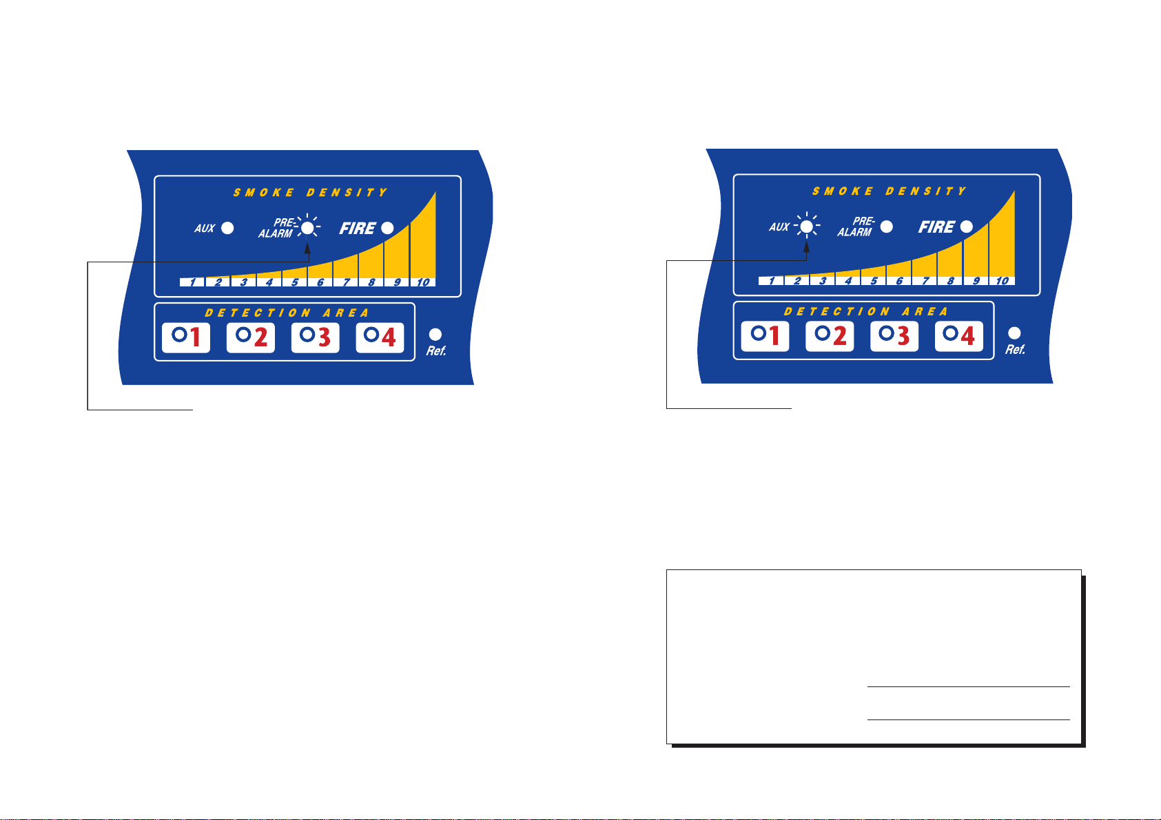
What do the lights mean?
These indicators are unique to Stratos-Quadra. The purpose of these
displays is to permit the display of four separate detection sectors with a
single display panel. The Detection Area LEDs index sequentially from
detectionarea1to4.WhentherelevantDetectionAreaLEDis flashing,the
entire display panel (including Isolate, Test & Reset keys) relate to the
detection area/pipe indicated. If a Reference Detector is connected, the
'Ref.' lamp is automatically enabled when the Stratos-Quadra is reset to
factory default settings During the interrogation/display time it will show
the condition of Air Flow, Detector, Power, Dust Separator and any alarms
within the area of its protection.
The LEDs will ordinarily scan at relatively high speed. This scan rate slows
for display purposes upon receipt of any fire or fault signal. The actual scan
speed for the separate sampling pipes is several times per second, so no
appreciable delay is experienced in generating alarms.
TheAirFlow,Detector,PowerandSeparatorshouldallhavetheirrespective
Greenlightson.IfaGreenlightextinguishes,ayellowlightwillcomeonand
afaultconditionwillbegenerated.Thisfaultconditionshouldnormallybe
transmittedtotheFireAlarm IndicatorPanelandapre-selected routinewill
automatically be carried out.
It is important to understand that if any of the yellow Fault lamps are
illuminated,thentheareainquestionmaynotbeprotectedbytheStratos®
system.
This alarm level is fixed at bargraph level 8. If the red FIRE light operates,
thissignalshouldalwaysbetransmittedtotheFireIndicatorPanel.Itisnow
usually time to commence evacuation procedures. Other actions in the
event of the FIRE lamp operating will depend upon the application, but
typically it would involve; power down of equipment, calling Fire Brigade
and input to first leg of automatic Fire Extinguishing systems. Follow
instructions given to you by your Fire Warden. Act strictly in accordance
with the Emergency Plan for your building or area.
As with the PRE-ALARM level, if no obvious smoke is present in the area, it
maybeusefultoverifyifthebargraphisstillilluminatedfortheareainwhich
thealarmisgenerated.Iftheyellowbargraphisnolongerilluminateditmay
mean that it was a transient burst of smoke which is no longer present. If
it remains illuminated, then it is likely that an incipient fire is present in the
area, or an unusual smoke producing process is taking place.
Extra audible or visual alarms will normally be sounding within the area
whichare driven fromto the controllingFireIndicator Panel.Urgentaction
is necessary.
NOTE - Because the Stratos®system is capable of detecting extremely low
levels of smoke, The staged alarm facility may be configured so that
increasing levels of alarm can signal an increasing degree of danger.
What to do if...
The red FIRE lam
p
is illuminated
Top line (Green)
Below (Yellow)
Detection areas
(Yellow) Bar Graph
(Yellow)
Alarm Levels (Red)

SMOKE DENSITY
Thistensegmentbargraphshowsthecurrentsmokedensitysensedbythesystem.This
bargraph also displays other information during the TEST routine (see below) and it
gives a 'rolling' single segment display during the fifteen minute duration Fastlearn™
routine.
The red AUX, PRE-ALARM & ALARM LED,s will operate when the bargraph display
reaches the pre-set levels at which the output relays operate.
TheTEST routine establishes thesettings programmedintothe detectorby operating
variousLED'sinsequence.Thesesettingsinclude;Thepositionofthealarmsinrelation
to the Bargraph, the duration of the Delays and the present sensitivity of the detector
being tested.
PUSH BUTTONS
(only operational when enabled at programmable functions 35, 36 and 37)
RESET- This button resets any latched Alarm or Fault relays. It also takes the unit out
of programming mode.
TEST-Thisbutton performsaself test onthe currently indicateddetector as shownon
the 'DETECTOR AREAS' display and shows; Alarm Levels, Time Delays and Detector
Sensitivity.
ISOLATE - This button puts the detector being indicated on the 'DETECTOR AREAS'
displayoff-line,wherebyitisnotcapableofgeneratinganyalarmsorfaults.Ifoperated,
a fault relay output will be generated, which will normally cause a Fault condition to
be indicated on the host Fire Indicator Panel.
Operation of any of the above buttons are recorded as separate entries in the detectors
eventlog.Entriesin this log areshownwithtimeand date of occurrence.Theeventlogcan
beprinted toa serial printervia Function45 or shownon Screenvia an IBM compatible PC
andthenprintedtothePC'sprinter.TheEventLogiscapableofstoringapprox.100entries,
and when it is full it over-writes the oldest event in the buffer.
Controls & Indicators
Detection areas
(Yellow) Push
Buttons
Alarm Levels (Red)
Operational Indicators
Display Meaning
Airflow OK illuminated steady Normal operation. The air flow is within limits.
Airflow OK flashing. The detector is currently setting up the air flow high and low thresholds.
Airflow HIGH illuminated steady The air flow is high. The sampling pipe may be broken.
Airflow LOW illuminated steady The air flow is low. The pipe may be blocked or the aspirator faulty.
Detector OK illuminated steady Normal detector module operation. No faults.
Detector FAULT flashing. The comms error rate is too large. Check that the unit is correctly earthed.
Detector FAULT illuminated steady A detector head fault or process error has occurred.
Detector ON illuminated steady Normal operation. The sector is on-line and capable of generating alarms.
Detector ISOL illuminated steady The detector is Isolated and not capable of generating alarms.
Detector ON flashing Demonstration mode has been entered. (see page 34)
Separator OK illuminated steady Normal separator operation. No faults.
Separator RENEW flashing The dust separator has been removed.
Separator RENEW steady The dust separator needs replacing.
Power OK illuminated steady Normal operation. No faults.
Power FAULT flashing Battery fault. The battery is discharged or not connected.
Power FAULT illuminated steady Mains fault. The system is running from stand-by batteries.

What to do if...
The AUX alarm may be programmed to operate between bargraph level 2
to10.Itisanalarmwhichmaybesettogivea'pre'pre-alarm,alternatively
it may be used as a post FIRE warning indicator. Actions in the event of an
AUX alarm will therefore vary according to the programmed setting of the
AUX alarm in the protected area.
What to do if...
This alarm level can be programmed to operate between bargraph levels 4
to 8. If the red PRE-ALARM light operates, this signal will often be
transmittedtotheFireIndicatorPanel.ActionsintheeventofthePre-Alarm
operating will depend upon the application, but typically it will involve
summoning assistance to find the source of smoke. (see note)
It will be useful to verify if the bargraph is still illuminated for the area in
whichthealarmisgenerated.Iftheyellowbargraphisnolongerilluminated
itmaymeanthatitwasatransientburstofsmokewhichisnolongerpresent.
Ifitremainsilluminated,then itislikelythatan incipientfireispresentin the
area, or an unusual smoke producing process is taking place.
Extra audible or visual alarms may now be sounding which are connected
to the Fire Indicator Panel. Urgent action is necessary.
You should contact your Supervisor or Floor Fire Warden immediately,
informing them of the problem.
NOTE-BecausetheStratos®systemiscapableofdetectingextremelylowlevels
of smoke, an alarm condition need not mean that the area needs to be
immediately evacuated. The staged alarm facility may be configured so that
increasing levels of alarm can signal an increasing degree of danger.
The AUX alarm is:- USED/UNUSED
The AUX alarm is set at level No:- 2 3 4 5 6 7 8 9 10
(Circle appropriate number)
The AUX alarm is used to:-
The red PRE-ALARM lam
p
is illuminated The red AUX lam
p
is illuminated
Other AirSense Smoke Alarm manuals
Popular Smoke Alarm manuals by other brands

Universal Security Instruments
Universal Security Instruments UNIVERSAL SS-770-LR user manual

olympia electronics
olympia electronics BS-506/LITHIUM quick start guide

Elkron
Elkron FO31WL quick start guide

NHR
NHR SG-01-SK-HB user manual

Firex
Firex I240C user manual

EST
EST Signature Series Installation sheet

Panasonic
Panasonic 4301 Specification sheet

System Sensor
System Sensor FAAST FL0111E-HS Quick installation guide

Challenger
Challenger SMART FORCE ASFSM Installation and operating instructions

Firehawk
Firehawk Fast-Fix user manual

PSA
PSA LIFESAVER LIFWMB2 quick start guide

Gamewell
Gamewell MS-7AF operating instructions