AEL FM-15QE User manual


MODEL
/
DATE
SERIAL NO.
‘,
I
TO:
WARRANTY
f!kller warrants
the Droducts of this contract. manufactured and sold by Seller, against failure dur to defects in mater-la{ and workman.
.
ship under normal use and
service for
a
period of from the date of original delivery when operated in accordance with
Seller’s operating instructions. This warranty shall not apply to tubes, fuses, bulbs, semiconductors, motors, meters and relays; however,
the warranties extended by the
original
manufacturers apply. All warranties whether expressed or implied (hereinafter collectively called
“warranties”) shall extend only to
the
Buyer and no
others.
Warranties are valid only when and if (a) Seller receives prompt written notice of the breach within the period of the warranty,
(b) the defective product is properly packed and returned by the Buyer (transportation and insurance prepaid), and (c) Seller determlnes,
in its sole judgment, that the product is defective and not subject to any misuse, neglect, improper installation. negligence, accident, or
(unless authorized in writing by Seller) repair or alteration. Seller’s exclusive obligation under all warranties, and Seller’s exclusive
liability
for any
personal and/or property damages (including direct, consequential or incidental) caused by the breach of any or all
warranties,
shall be limited to the following: (a) repairing or replacing (in Seller’s sole discretion) any defective parts free of charge
(f.o.b. Seller’s plant), and/or (b) crediting (in Seller’s sole discretion) all or a portion of the purchase price to the Buyer.
SELLER DOES NOT WARRANT
MERCHANTABILITY OF GOODS OR-PARTS THEREOF NOT MANUFACTURED BY SELLER
THERE ARE NO WARRANTIES THAT EXTEND BEYOND THE DESCRIPTION ON THE FACE HEREOF OR BEYOND THE
TERMS AND CONDITIONS CONTAINED HEREIN.
GUARANTEE
American Electronic
Laboratories,
Inc.
also
agrees to make available for purchase by Buyer the replaceable parts for the transmitters and
excite?, and
stereo generators
sold hereunder for a
period
of ten (10) years at the price charged by AEL to others for said parts.
i
www.americanradiohistory.com
Table of Contents
Section Page ,-
I GENERAL DESCRIPTION
l-l.
Introduction
l-2,
Physical Description
l-3. Electrical Description
l-4. Specifications
l-l
l-l
l-l
l-l
II
INSTALLATION
2-l.
Unpacking and Inspection
2-2. Mechanical Installation
2-3. Environmental Requirements
2-4. Mounting Requirements
2-5. Electrical InstaIIation
2-6. AC Power
2-7. Low Output Power Operation
2-8. Monaural Transmission
2-9. Stereo Transmission
2-10.
SCA Transmission
2-l
2-l
2-l
2-l
2-l
2-l
2-l
2-3
2-3
2-3
2-11. External Meter 2-3
2-12. RF Output 2-3
2-13. Installation Checkout 2-3
III OPERATION
3-l. Controls and Indicators
3-2. Operating Procedure
-
3-l
3-l
IV THEORY OF OPERATION
4-l.
4-2,
4-3.
4-4,
4-5.
4-6.
4-7.
4-8.
4-9.
Overall theory
FM0 and Phase Lock Assembly
IPA and PA
Power Supply-ReguIator ’
Detailed Theory
FM0 and Phase Lock Assembly
IPA and PA
Power Supply-Regulator
Power
and Signal Distribution
4-1
4-1
4-l
4-1
4-2
4-2
4-3
4-3
4-4
MAINTENANCE
5-1. Preventive Maintenance
5-2. Access to Components
5-3. Test Equipment
5-4. Introduction to Troubleshooting
5-5. Troubleshooting Chart
5-1
5-l
5-1
5-1
5-l
ii
www.americanradiohistory.com
Table of Contents (ConVd)
Section
5-6. Removal and Replac em ent Procedures 5-11
5-7. Alignment and Adjustment 5-11
5-8, Frequency Programming 5-1.2
5-9. FM0 and Phase Lock AFC Adjustment 5-12
5-10. FM0 and Phase Lock Coarse Frequency Adjustment 5-12
5-11. IPA and PA Coarse Alignment 5-16
5-12. IPA and PA Final Alignment 5-16
5-13. FM0 and Phase Lock Modulation Level Adjustment 5-17
5-14. &check Coarse Frequency Adjustment 5-17
5-15, Proof of Performance Test 5-17
PARTS LISTS
6-1. Ordering Information
6-2. Parts Lists
DIAGRAMS
Page
6-1
6-1
...
111
www.americanradiohistory.com
List of Illustrations
Figure
l-l
2-l
3-l
5-1
5-2
5-3
5-4
5-5
Number
l-l
3-l
5-l
5-2 ’
5-3
iv
Title
FM-15QE FM Exciter
FM-15QE
Exciter
Rear Panel
FM-15QE Exciter Controls and Indicators
FM-15QE Exciter Top View with
Cover
Removed
FM-15QE Exciter Bottom View with
Cover
Removed
FM0
and Phase Lock Assembly, Location of Parts
IPA and PA Assembly, Location of Parts
Power
Supply-Regulator Assembly, Location of Parts
l-2
2-2
3-3
5-2
5-3
5-4
5-5
5-6
List of Tables
Tit1 e Page -
Specifications l-3
Exciter
Controls and Indicators
3-2
Recommended Test Equipment
5-7
Troubleshooting Chart
5-8
Frequency Programming
5-13
www.americanradiohistory.com

SECTION I
GENERAL DESCRIPTION
I-1. INTROD-UCTION.
This manual contains information for installation, operation, and maintenance of the AEL
FM-15QE FM exciter (figure I-1). The necessary drawings are included with, but not
bound into, the manual.
The FM-15QE was designed and
built
for the professional FM broadcaster
and
is
an all
solid-state, on-carrier, direct FM, phase locked, frequency synthesized exciter. The
FM-15QE was designed to meet or exceed FCC requirements for use in the standard FM
broadcast band (88 to 108 MHz).
l-2. PHYSICAL DESCRIPTION.
The exciter is housed in a 3-l/2 X 19 X 14 in. enclosure for mounting in
a
standard
equipment rack. All operator controls and indicators are located on the front panel.
The rear panel contains signal input and output connectors, the ac power line cord and
fuse, and the switch for selecting mono or stereo input signals.
The exciter is identified by a model number and serial number located on the rear
panel. All correspondence in regard to this unit should reference the complete model
and serial numbers.
1-3. ELECTRICAL DESCRIPTION.
The exciter is all solid-state, employing silicon transistors, diodes, and integrated
circuits and featuring phase-locked stability and on-carrier direct FM for full multi-
plex operation with freedom from spurious responses. The exciter can withstand any
VSWR phase or magnitude and provides a power output adjustable from less than 5 to
greater than 20 watts. Also, the exciter may be programmed to operate on any 100
kHz increment in the FM band by using the internal 8 MHz crystal as a reference.
1-4. SPECIFICATIONS.
Table l-1 lists the electrical and mechanical specifications for the FM-15QE exciter.
l-1
www.americanradiohistory.com


Table 1-l. Specifications
Parameter Specification
Dimensions
Mounting Dimensions
Net Weight
Shipping Weight
Maximum Operating Temp
Environmental
Primary Power
Power Consumption
Power Output
Frequency Range
Type of Emission
Modulation Capability
(less than I percent THD)
Frequency Stability
Output Impedance
VSWR Protection
AM Noise
Stereo Separation
MECHANICAL
3-l/2 in. H X 19 in. W X 14 in. D
Standard 19 in. rack
12
lb.
16 lb.
131°F (55OC) ambient
0°C to +55”C operating
(-15OC to +55”C with 30 min. warm up)
ELECTRICAL
1050l-25/210/250 Vat, 50/60 Hz
Approx 50 watts max.
Adjustable from less than 5 to greater
than 20 watts
88 to 108 MHz (programmable)
180F3 or 300F9
150 kHz peak
+ 500 Hz (-lO*C to +55”C)
-
50 ohms
Any magnitude or phase
Better than -55 dB
Better than 40 dB from 30 Hz to 15 kHz
with AEL Model FM-15QE/SG Stereo
Generator
l-3
www.americanradiohistory.com

Table I-1. Specifications (Cont’d)
Parameter
Crosstalk (Main to SCA)
Crosstalk (SCA to Main)
Harmonic and Spurious Suppression
Mono Input:
a. Impedance
b. Level
c. Pre-emphasis
Stereo Input:
a. Impedance
b. Level
SCA Inputs (2):
a. Impedance
b. Level
Distortion
FM Noise
(below 75 kHz dev. with 75 usec
de-emphasis)
Specification
-55
dB
-65
dB
Better than 80 dB (with optional harmonic
filter)
600 ohms (balanced)
r10 dBm for 75 kHz dev, at 400 Hz
75 usec 2 1 dB (50 usec optional)
IOk ohms
4Vpp for 75 kHz deviation
10k ohms
1Vpp for 10 percent injection
0.35 percent max. T&IL) at 75
kHz
dev.
Better than -70 dB
www.americanradiohistory.com
-
---
---
-
SECTION II
INSTALLATION
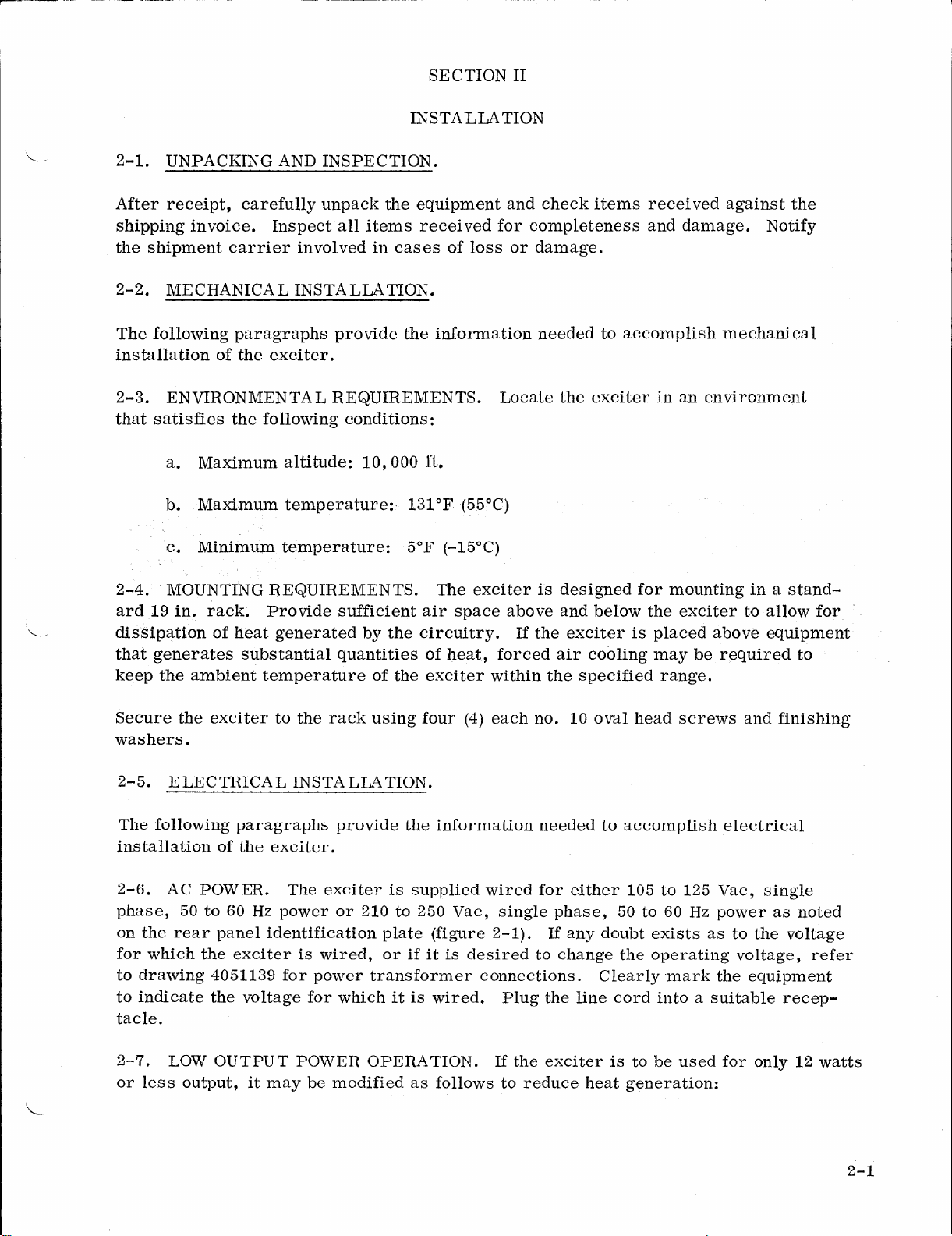
2-l. UNPACKING AND INSPECTION.
After receipt, carefully unpack the equipment and check items received aga
shipping invoice. Inspect all items received for completeness and damage.
the shipment carrier involved in cases of loss or damage.
inst the
Notify
2-2. MECHANICAL INSTALLATION.
The following paragraphs provide the information needed to accomplish mechanical
installation of the exciter.
2-3. ENVIRONMENTAL REQUIREMENTS. Locate the exciter in an environment
that satisfies the following conditions:
a. Maximum altitude: 10,000 ft.
b. Maximum temperature:, 131°F (55OC)
C.
Minimum temperature: 5°F (-15*C)
2-4. MOUNTING REQUIREMENTS. The exciter is designed for mounting in a stand-
ard 19 in. rack. Provide sufficient air space above and below the exciter to allow for
dissipation of heat generated by the circuitry. If the exciter is placed above equipment
that generates substantial quantities of heat, forced air cooling may be required to
keep the ambient temperature of the exciter within the specified range.
Secure the exciter to the rack using four (4) each no. 10 oval head screws and finishing
washers.
2-5. ELECTRICAL INSTALLATION.
The following paragraphs provide the information needed to accomplish electrical
installation of the exciter.
2-6. AC POWER. The exciter is supplied wired for either 105 to 125 Vat, single
phase, 50 to 60 Hz power or 210 to 250 Vat, single phase, 50 to 60 Hz power as noted
on the rear panel identification plate (figure 2-l). If any doubt exists as to the voltage
for which the exciter is wired, or if it is desired to change the operating voltage, refer
to drawing 4051139 for power transformer connections. Clearly .mark the equipment
to indicate the voltage for which it is wired. Plug the line cord into a suitable recep-
tacle.
2-7. LOW OUTPUT POWER OPERATION. If the exciter is to be used for only 12 watts
or less output, it may be modified as follows to reduce heat generation:
2-l
www.americanradiohistory.com

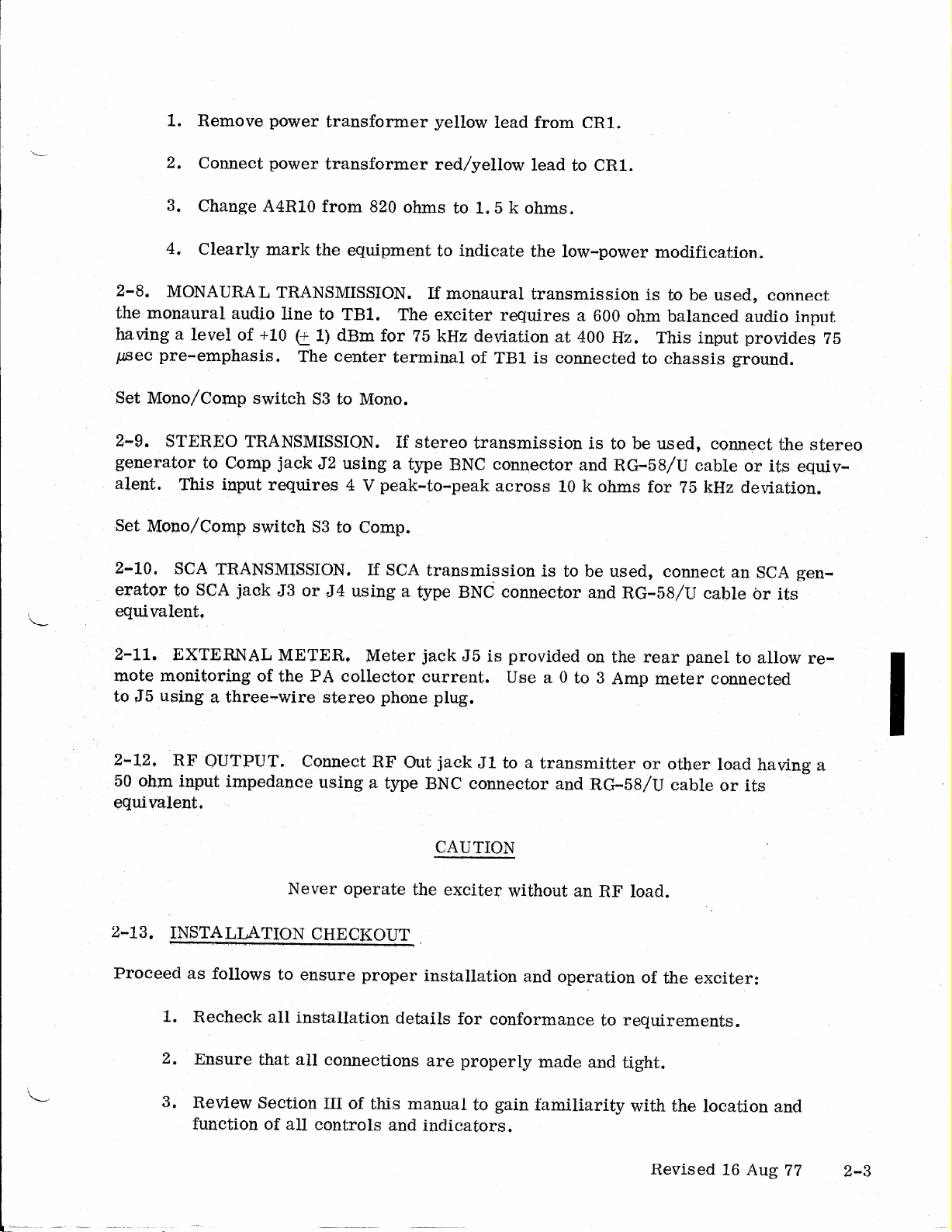
1. Remove power transformer yellow
lead
from CRl.
2. Connect power transformer red/yellow lead to CRl.
3. Change A4RIO from 820 ohms to 1.5 k ohms.
4. Clearly mark the equipment to indicate the low-power modification.
2-8. MONAURAL TRANSMISSION. If monaural transmission is to be used, connect
the monaural audio line to
TBl.
The exciter requires a 600 ohm balanced audio input
having a level of +10 e I) dBm for 75 kHz deviation at 400 Hz. This input provides 75
pet pre-emphasis. The center terminal of TBl is connected to chassis ground.
Set Mono/Camp
switch S3 to Mono.
2-9. STEREO TRANSMISSION. If stereo transmission is to be used, connect the stereo
generator to Comp jack 52 using a type BNC connector and RG-58/U cable or its equiv-
alent. This input requires 4 V peak-to-peak across 10 k ohms for 75 kHz deviation.
Set Mano/Comp switch S3 to Comp.
2-10, SCA TRANSMISSION. If SCA transmission is to be used, connect an SCA gen-
erator to
SCA
jaak J3 or J4 using a type BNC connector and RG-58/U cable br its
equivalent,
Z-11. EXTERNAL METER, Meter jack 55 is provided
04
the rear panel to allow re-
mote monitoring of the PA collector current. Use a 0 to 3 Amp meter connected
to JS using a three-wire stereo phone plug.
2-12, RF OUTPUT.
Connect RF Out jack J1 to a transmitter or other load having a
50 ohm input impedance using a type BNC connector and RG=58/U cable or its
equivalent.
CAUTION
Never operate the exciter without an RF load.
2-13. INSTALLATION
CHECKOUT .
Proceed as follows to ensure proper installation and operation of the exciter:
1. Recheck all installation details for conformance to requirements.
2. Ensure that all connections are properly made and tight.
3. Review Section HI of this manual to gain familiarity with the location and
function of all controls and indicators.
Revised 16 Aug 77 2-3
www.americanradiohistory.com

I
SECTION III
L-
OPERATION
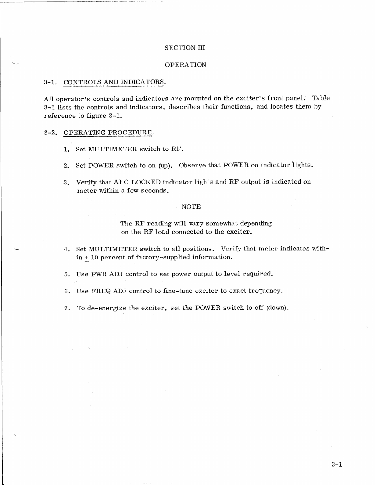
3-1. CONTROM AND INDICATORS.
All operator% controls and indicators are mounted on the exciter’s front panel. Table
3-1 lists the controls and indicators, describes their functions, and locates them by
reference to figure 3-1.
3-2. OPERATING PROCEDURE.
1. Set MULTIMETER switch to RF.
2. Set POWER switch to on (up). Observe that POWER on indicator lights.
3. Verify that AFC LOCKED indicator lights and
RF
output is indicated on
meter within a few seconds.
NOTE
The RF reading will vary somewhat depending
on the RF load connected to the exciter.
4. Set MULTIMETER switch to all positions. Verify that meter indicates with-
in + 10 percent of factory-supplied information.
5. Use PWR ADJ control to set power output to level required.
6. Use FREQ ADJ control to fine-tune exciter to exact frequency.
7. To de-energize the exciter, set the POWER switch to off (down).
3-1
www.americanradiohistory.com

Table 3-1. Exciter Controls and Indicators
Item Control or Indicator Function
1 Power switch Applies ac power to exciter when set to
the up position.
2 POWER on indicator Indicates, when lit, that ac power is ap-
plied to exciter
3 MULTIMETER meter Indicates, on a scale of 0 to 1, the relative
levels of functions selected by MULTI-
METER switch.
4 MULTIMETER switch, having Selects various exciter functions for dis-
positions as follows: play on meter:
vcc Power to integrated circuits
+I5 v Output of 15 Volt power supply.
+5 v Output of 5 Volt power supply.
Ref Reference oscillator level,
Fmo FM oscillator RF level.
IPA IPA power output (IPA collector current)
PA PA power output (PA collector current)
RF Exciter RF output.
5 PWR ADJ control Screwdriver adjustment to set level of ex-
citer RF output over a range of approx 5
to
20 watts.
6 FREQ ADJ control Screwdriver adjustment to fine-tune exciter
output RF output over a range of approx
* 500 Hz.
7 AFC LOCKED indicator Indicates, when lit, that exciter output
frequency is locked to the internal ref-
erence oscillator.
3-2
www.americanradiohistory.com


SECTION IV
THEORY OF OPERATION
4-1. OVERALL THEORY.
Refer to drawing 3050688 for a block diagram of the exciter. The exciter is divided
into three functional areas :
a. Frequency Modulation Oscillator (FMO) and Phase Lock - A2 assembly
b. Intermediate Power Amplifier (IPA) and Power Amplifier (PA) - A3 assembly
c. Power Supply and Regulator - A4 assembly.
4-2. FM0 AND PHASE LOCK ASSEMBLY. The FM0 receives pre-emphasized mon-
aural audio, a composite (camp) audio signal from a stereo generator, or up to two
SCA inputs. The FM0 produces the basic frequency modulated signal which is ampli-
fied by the FM0 buffer and control amplifier to approximately 100 mw. This signal is
then sent to the IPA and PA assembly.
A sample of the signal from the FM0 buffer is fed to a high speed divider which reduces
the frequency to nominally 5 MHz (Fc/ZO). This 5 MHz signal is then processed by the
programmable divider which has an output of 5 kHz regardless of the selected frequency.
The output of an 8 MHz crystal controlled oscillator is digitally divided to 5 kHz. This
signal is phase compared with the output of the programmable divider; the resulting sig-
nal is filtered .and used to control the FM0 subassembly. Thus, the programmable div-
ider allows the use of the same high stability 8 MHz reference crystal regardless of
channel assignment.
Note that this phase locked loop requires a phase error, not a frequency error, to gen-
erate its correction signal. Because of this, the output of a phase locked exciter exhibits
long term phase coherence with the reference oscillator without the frequency drift as-
sociated with frequency locked loop exciters.
The lock detector senses loss of phase coherence and provides a signal that cuts off the
control amplifier thereby shutting off the RF output until lock is established.
4-3. IPA AND PA. The IPA and PA assembly contains a two-stage power amplifier
which raises the 100 mw output of the FM0 and Phase Lock assembly to a maximum
level of approximately 20 watts.
4-4. POWER SUPPLY - REGULATOR. The Power Supply - Regulator assembly con-
tains a power supply-regulator for the IPA and PA, for the FM0 (+15 Vdc), and for the
FM0 logic circuits (+5 Vdc). These supplies are short circuit protected. The supply-
reelator for the IPA and PA can be continuously varied from 14 Vdc to 24 Vdc by us-
ing the front panel PWR ADJ control. This allows control over the power output of the
IPA and PA assembly.
4-1
www.americanradiohistory.com
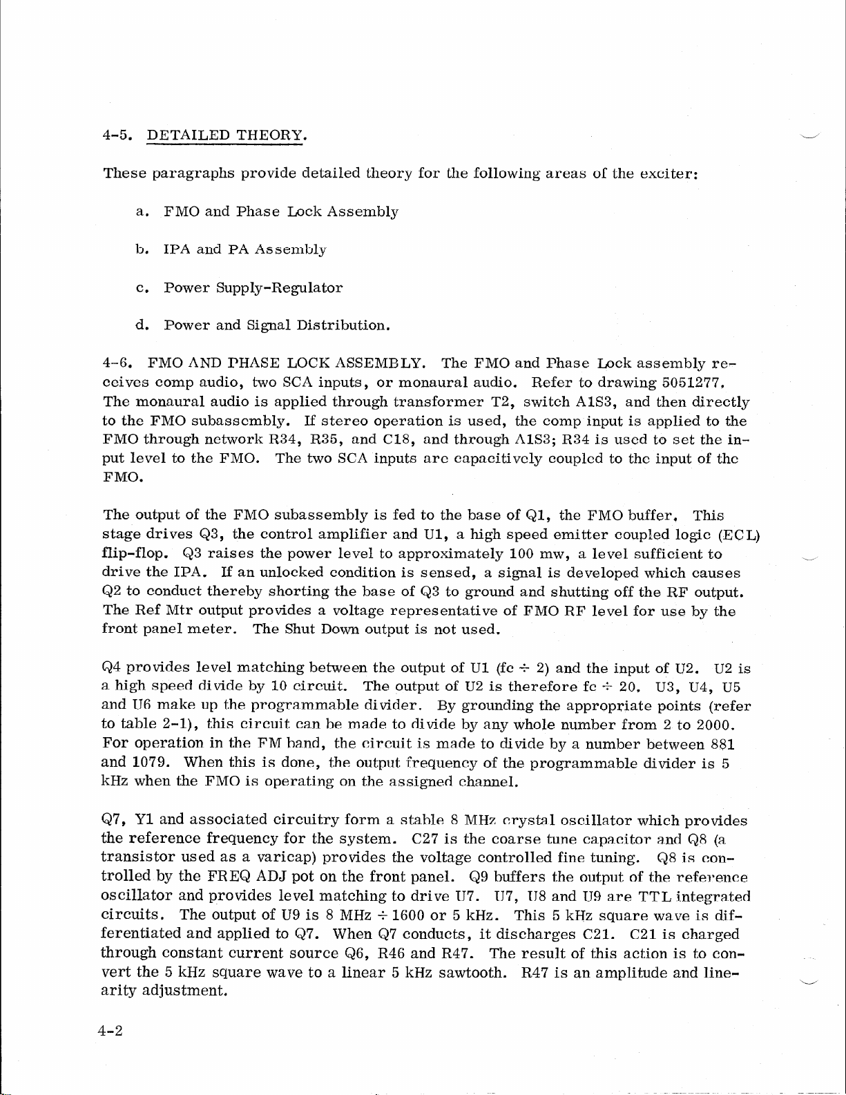
4-5. DETAILED THEORY.
These paragraphs provide detailed theory for the following areas of the exciter:
a. FM0 and Phase Lock Assembly
b. IPA and PA Assembly
c.
Power Supply-Regulator
d. Power and Signal Distribution.
4-6. FM0 AND PHASE LOCK ASSEMBLY. The FM0 and Phase Lock assembly re-
ceives camp audio, two SCA inputs, or monaural audio. Refer to drawing 5051277,
The monaural audio is applied through transformer T2, switch AlS3, and then directly
to the FM0 subassembly. If stereo operation is used, the camp input is applied to the
FM0 through network R34, R35, and C18, and through A1S3; R34 is used to set the in-
put level to the FMO. The two SCA inputs are capacitively coupled to the input of the
FMO.
The output of the FM0 subassembly is fed to the base of Ql, the FM0 buffer, This
stage drives Q3, the control amplifier and Ul, a high speed emitter coupled logic (ECL)
flip-flop. Q3 raises the power level to approximately 100 mw, a level sufficient to
drive the IPA. If an unlocked condition is sensed, a signal is developed which causes
$2 to conduct thereby shorting the base of Q3 to ground and shutting off the RF output.
The Ref Mtr output provides a voltage representative of FM0 RF level for use by the
front panel meter. The Shut Down output is not used.
-
Q4 provides level matching between the output of Ul (fc + 2) and the input of U2. U2 is
a high speed divide by 10 circuit. The output of U2 is therefore fc f 20. U3, U4, U5
and US make up the programmable divider. By grounding the appropriate points (refer
to table 2-l), this circuit can be made to divide by any whole number from 2 to 2000.
For operation in the FM band, the circuit is made to divide by a number between 881
and 1079. When this is done, the output frequency of the programmable divider is 5
kHz when the FM0 is operating on the assigned channel.
Q7, Yl and associated circuitry form a stable 8 MHz crystal oscillator which provides
the reference frequency for the system. C27 is the coarse tune capacitor and QS (a
transistor used as a varicap) provides the voltage controlled fine tuning. QS is con-
trolled by the FREQ ADJ pot on the front panel. Q9 buffers the output of the reference
oscillator and provides level matching to drive U7. U7, U8 and U9 are TTL integrated
circuits. The output of U9 is 8 MHz f 1600 or 5 kHz. This 5 kHz square wave is dif-
ferentiated and applied to Q7. When Q7 conducts, it discharges C21. C21 is charged
through constant current source Q6, R46 and R47, The result of this action is to con-
vert the 5 kHz square wave to a linear 5 kHz sawtooth. R47 is an amplitude and line-
arity adjustment. ii
4-2
www.americanradiohistory.com
The 5 kHz output of the programmable divider drives pulse amplifier Q5. The output
of Q5 and the sawtooth converter are coupled to U12. This IC and associated circuitry
form a sample hold phase detector. U12 is a gated Operational Transconductance
Amplifier. This device has a high impedance (constant current) output. R39 and C20
form a storage circuit, U12 charges this storage circuit to the point on the input saw-
tooth which is coincident with the pulse from Q5. Therefore, as the phase angle be-
tween the reference derived and the FM0 derived 5 kHz signals changes, the voltage
on C20 rides up or down. However, since the voltage can change only when the pulse
from Q5 is present, the filter required to eliminate the reference frequency is greatly
reduced. Ull is a high input impedance voltage follower which eliminates any loading
of the storage circuit. The low impedance output of Ull is filtered and applied to the
AFC control port of the FM0 subassembly thereby closing the control loop.
QlO buffers the output of U9 (reference 5 kHz) and drives the REF position on the
MULTIMETER.
UlO, Qll and Q12 form the circuit that senses lock. A 5 kHz square wave from U9 and
a 5 kHz pulse from the programmable divider are fed to UIO. If the two inputs are not
locked, a square wave will appear at pin 6 of Ul.0. This signal is converted to a DC
level by Qll and this level is applied to Q12 which drives the other half of Ul.0. The
output of UIO is then fed to Q2 where it shuts down the RF output and to Q13 which turns
off the AFC LOCKED lamp.
4.7. IPA AND PA. The output of the FM0 and Phase Iock assembly (approximately
100 mw) is applied to Tl. Refer to drawing 4051142. Tl and T2 provide impedance
matching to the base of &I, the IPA. C2 stabilizes the amplifier throughout the power
adjust range. C7, C8 and L2 provide impedance matching between the collector of Ql
and the base of Q2, the PA. L5, Cl4 and Cl5 provide impedance matching between the
collector of Q2 and the load, CR1 and associated circuitry drives the RF position on
the MULTIMETER. Parallel bypass capacitors are used on both stages to ensure that
the power supply is bypassed for all frequencies. This precaution is necessary due to
the extremely high low frequency gain of RF power transistors. If adequate bypassing
is not used, low frequency oscillations of a sufficient magnitude to destroy the transis-
tor can occur.
4-8. POWER SUPPLY - REGULATOR. The Power Supply-Regulator receives unregu-
lated dc voltage from a chassis mounted rectifier. This unregulated voltage is distributed
to the IPA-PA regulator, the 15 volt regulator, andthe 5 volt regulator, Refer to
drawing
4051141.
IPA-PA Regulator. A 12 volt zener diode, CR4, is the reference for this supply. The
PWR ADJ control Rl (front panel control, across pins H and S) supplies all or part of
the 12 volts across CR4 to the base of Q2. Q2 and Q3 form a DC amplifier with a gain
of approximately 2. This raises the voltage supplied to the base of pass transistor
AlQl (mounted on heat sink at rear of unit) to approximately 24.7 volts max. The
4-3
www.americanradiohistory.com
Table of contents


